Hardware Installation Guide for Cisco 8400 Series Secure Routers

PDF

Hardware Installation Guide for Cisco 8400 Series Secure Routers

SFP modules

Want to summarize with AI?

Log in

Guides users through the handling of SFP and SFP+ modules, addressing laser safety, and providing step-by-step instructions for removing these modules.


Before you begin

See Cisco Optics to Device Compatability Matrixfor a list of supported SFP modules. Use only supported SFP/SFP+/SFP28 modules on the router.

  • Do not remove the dust plugs from the SFP modules or the rubber caps from the fiber-optic cable until you are ready to connect the cable. The plugs and caps protect the module ports and cables from contamination and ambient light.

  • Removing and installing an SFP module can shorten its useful life. Do not remove and insert any SFP module more often than is necessary.

  • To prevent ESD damage, follow your normal board and component handling procedures when connecting cables to the switch and other devices.

  • When you insert several SFP modules in multiple ports, wait for 5 seconds between inserting each SFP. This will prevent the ports from going into error disabled mode. Similarly, when you remove an SFP from a port, wait for 5 seconds before reinserting it.

Procedure

1.

Attach an ESD-preventive wrist strap to your wrist and to an earth ground surface.

2.

Find the send (TX) and receive (RX) markings that identify the top of the SFP module.

On some SFP/SFP+ modules, the send and receive (TX and RX) markings might be shown by arrows that show the direction of the connection.
3.

If the SFP module has a bale-clasp latch, move it to the open, unlocked position.

4.

Align the module in front of the slot opening, and push until you feel the connector snap into place.

5.

If the module has a bale-clasp latch, close it to lock the SFP module in place.

6.

Remove the SFP dust plugs and save.

7.

Connect the SFP cables.


Laser safety guidelines

Optical SFPs use a small laser to generate the fiber-optic signal. Keep the optical transmit and receive ports covered whenever a cable is not connected to the port.

Warning

Statement 1255—Laser Compliance Statement

Pluggable optical modules comply with IEC 60825-1 Ed. 3 and 21 CFR 1040.10 and 1040.11 with or without exception for conformance with IEC 60825-1 Ed. 3 as described in Laser Notice No. 56, dated May 8, 2019.

Follow these steps to install an SFP module in your router:

Procedure

1.

Read the Safety Warnings section and disconnect the power supply before you perform any module replacement.

2.

Slide the SFP into the router connector until it locks into position

Tip

If the SFP uses a bale-clasp latch (see Laser Safety Guidelines section, the handle should be on top of the SFP module.

Caution

Do not remove the optical port plugs from the SFP until you are ready to connect cabling.

3.

Connect the network cable to the SFP module.


Remove small form-factor pluggable modules

Follow these steps to remove a Small Form-Factor Pluggable (SFP) from the device:

Procedure

1.

Read the Safety Warnings section and disconnect the power supply before you perform any module replacement.

2.

Disconnect all cables from the SFP.

Caution
The latching mechanism used on many SFPs locks the SFP into place when cables are connected. Do not pull on the cabling in an attempt to remove the SFP.
3.

Disconnect the SFP latch.

Note
SFP modules use various latch designs to secure the module in the SFP port. Latch designs are not linked to SFP model or technology type. For information on the SFP technology type and model, see the label on the side of the SFP.
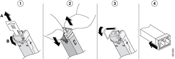
Figure 1. Disconnecting SFP Latch Mechanisms

Number

Description

1

Sliding latch

2

Swing and slide latch

3

Bale-clasp latch

4

Plastic collar latch

Tip

Use a pen, screwdriver, or other small straight tool to gently release a bale-clasp handle if you cannot reach it with your fingers.

4.

Grasp the SFP on both sides and remove it from the device.