Hardware Installation Guide for Cisco 8400 Series Secure Routers

PDF

Hardware Installation Guide for Cisco 8400 Series Secure Routers

Remove and replace DDR DIMMs

Want to summarize with AI?

Log in

Guides you through handling DDR DIMMs, covering identification, orientation, safe removal, and installation processes to upgrade or replace system memory modules.


To access the DIMMs, you must remove the chassis cover as described in the Access and Install Modules section.

Caution

Always wear an ESD-preventive wrist strap and ensure that it makes good contact with your skin when you remove or install DIMMs. Connect the equipment end of the wrist strap to the metal part of the chassis.

Caution

Handle DIMMs by the edges only. DIMMs are ESD-sensitive components and can be damaged by mishandling.
Locate and orient DIMM

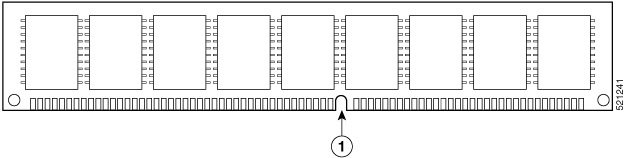
DIMMs have a polarization notch on the mating edge to prevent incorrect insertion. This image shows the polarization notch on a DIMM.

Figure 1. DIMM showing polarization notch

Number

Description

1

Polarization notch


Remove a DIMM

Use these steps to remove a DIMM:

Procedure

1.

Read the Safety Warnings section and disconnect the power supply before you perform any module replacement.

2.

Remove the chassis cover. See the Remove the Chassis Cover section

3.

Locate the DIMM module to find the DIMM sockets on the chassis.

4.

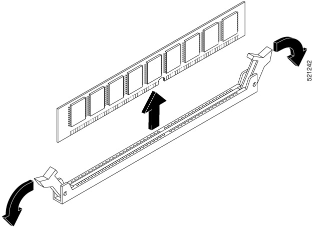
Rotate DIMM connector handles downwards to extract the DIMM module.

Figure 2. Remove a DIMM

Install a DIMM

Follow these steps to install a DIMM on the Cisco 8400 Series Secure Routers.

Procedure

1.

Read the Safety Warnings section and disconnect the power supply before you perform any DIMM replacement.

2.

Remove the chassis cover.

3.

Locate the DIMM module to find the DIMM sockets on the device.

4.

Ensure that both latches on the DIMM connector are in the open position.

5.

Orient the DIMM so that the polarization notch lines up with the polarization key on the connector.

6.

Insert the DIMM into the connector one side at a time.

7.

Rotate the connector handles upward and click into place.

Figure 3. DIMM showing polarization notch
8.

Replace the chassis cover.