Hardware Installation Guide for Cisco 8400 Series Secure Routers

PDF

Hardware Installation Guide for Cisco 8400 Series Secure Routers

Fan tray

Want to summarize with AI?

Log in

Explains fan tray replacement, detailing the process and precautions necessary to maintain system cooling and ensure reliable operation.


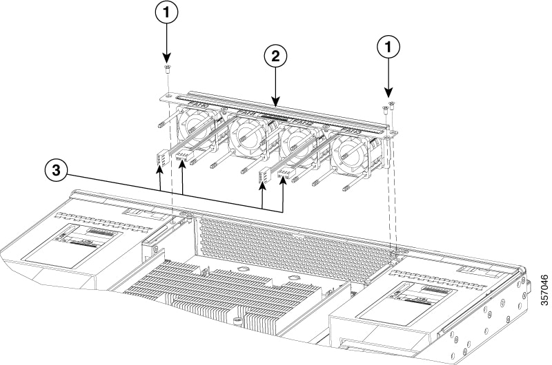
In the Cisco 8400 Series Secure Routers, there is a field replaceable unit (FRU) fan tray. The fan tray includes all the fans in one assembly. If a fan fails, replace the tray using a #1 Phillips screwdriver.

Remove the fan tray

To remove the fan tray, complete the following steps:

Procedure

1.

Remove the top cover. See Remove the chassis cover.

2.

Remove the three screws that secure the fan tray to the chassis.

3.

Disconnect fan cables from the motherboard.

4.

Remove the fan tray.

Figure 1. Fan tray

Number

Description

1

Screws

2

Fan Tray

3

Fan cable connectors

Install the fan tray

The Cisco C8400 series routers supports forward air flow (standard version). To install the fan tray, perform the following steps :

Procedure

1.

Install the fan tray.

2.

Install the three fan tray mounting screws.

3.

Connect the fan cables to the motherboard.

Note

The fan number (FAN0, FAN1, FAN2, and FAN3) is marked on the top of the fan tray and the motherboard by its connector. The fan wire should be connectedto its corresponding connector on the motherboard.

4.

Install the top cover

5.

Re-install the unit back in an equipment rack.

6.

Reinstall all cables from the chassis

7.

Power on the unit.