Hardware Installation Guide for Cisco 8400 Series Secure Routers

PDF

Hardware Installation Guide for Cisco 8400 Series Secure Routers

Install the routers

Want to summarize with AI?

Log in

Guides you through the complete router installation process, covering chassis mounting options such as rack installation, bracket attachment, mid-mounting, and four-post rack mounting for various deployment scenarios.


If you need to install Field-Replaceable Units (FRUs), you can install them either before or after you install the device. Ideally, you install the modules when you have access to the I/O side of the device. Internal modules (memory cards and fan trays) should be installed before rack-mounting.

The Cisco 8400 Series Secure Routers are designed to be rack-mounted.

Warning

Before working on a system that has an on/off switch, turn OFF the power and unplug the power cord that is in the chassis. Statement 1

Caution

To prevent damage to the chassis, do not attempt to lift or tilt the chassis by holding it by the plastic panel on the front. Always hold the chassis by the sides of the metal body.
Mount the chassis on a rack

Warning

This equipment must be grounded. Never defeat the ground conductor or operate the equipment in the absence of a suitably installed ground conductor. Contact the appropriate electrical inspection authority or an electrician if you are uncertain that suitable grounding is available.

Warning

To prevent the system from overheating, do not operate it in an area that exceeds the maximum recommended ambient temperature of 40C degrees on a continuous basis.

The Cisco 8400 Series Secure Routers can be installed in a 19-inch (48.26-cm) EIA or a 23-inch (58.42-cm) Southwestern Bell Corporation (SBC) racks. The Cisco 8400 Series Secure Routers can also be mounted in a 600-mm ETSI rack. Use the standard brackets shipped with the router for mounting the chassis in a 19-inch EIA rack; you can order optional larger brackets for mounting the chassis in a 23-inch SBC rack.

You can mount the devices in the following ways:

  • PS Mounting—Brackets are attached at the PS side of the chassis with the the PSUs facing forward.

  • I/O Mounting—Brackets are attached at the I/O side of the chassis with the I/O side facing forward.

  • Mid-Mounting —Brackets can be recessed or rotated to support multiple mounting-depth options.


Attach the rack-mounting brackets

Caution

Do not over-torque the screws. The recommended torque is 15 to 18 inch-lbs (1.7 to 2.0 N-m).

Caution

Your chassis installation must allow unrestricted airflow for chassis cooling.

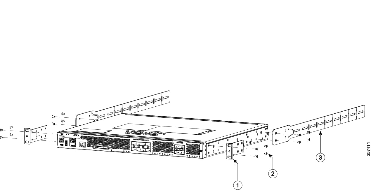
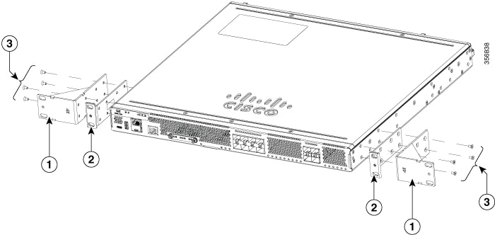
Attach the mounting brackets to the chassis as shown in the below figure using the screws provided. Use a #2 Philips screwdriver.

To attach the rack-mounting brackets to the Cisco 8400 Series Secure Routers , perform these steps:

Step1. Select the depth location for the router in the equipment rack.

Step2. Align the rack mount bracket with the mounting holes in the side of the router.

Step3. Insert the #6-32 FHM screws. Use only the screws that are provided in the rack mount bracket kit.

Step4. Tighten the screws to a torque value of 15 to 18 inch-lb. (1.7 to 2.0 N-m).

Figure 1. Installation of 19" or 23" brackets (I/O side shown)

This image is for reference only.

1

23-inch brackets

2

19-inch EIA brackets

3

Screws (#6-32 FHMS )

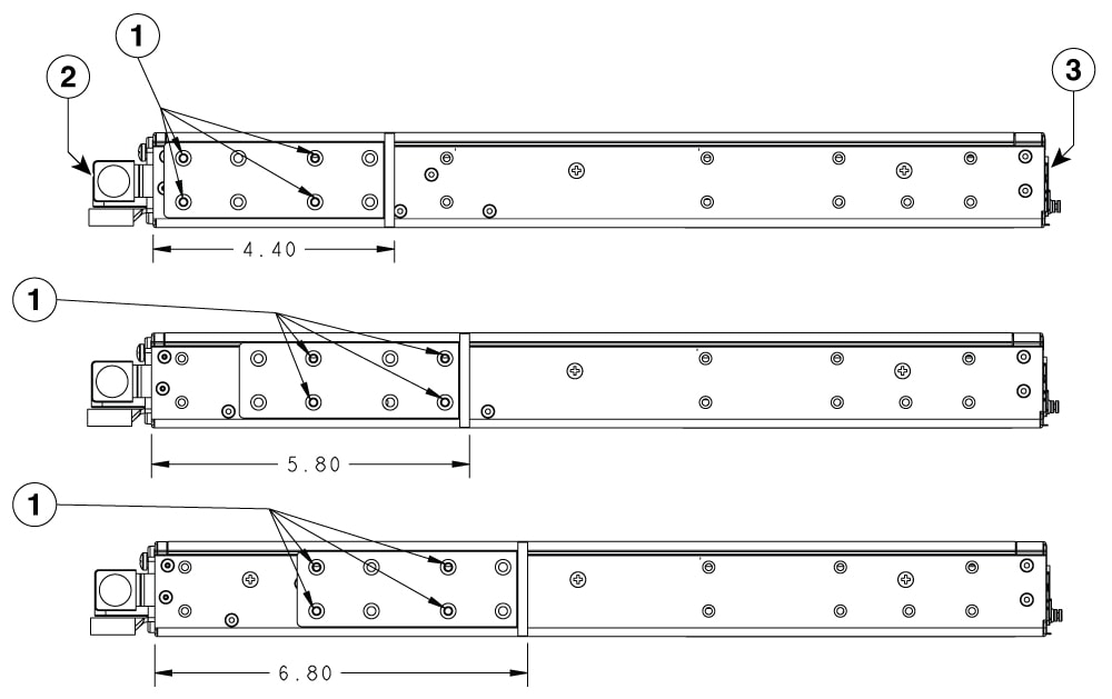
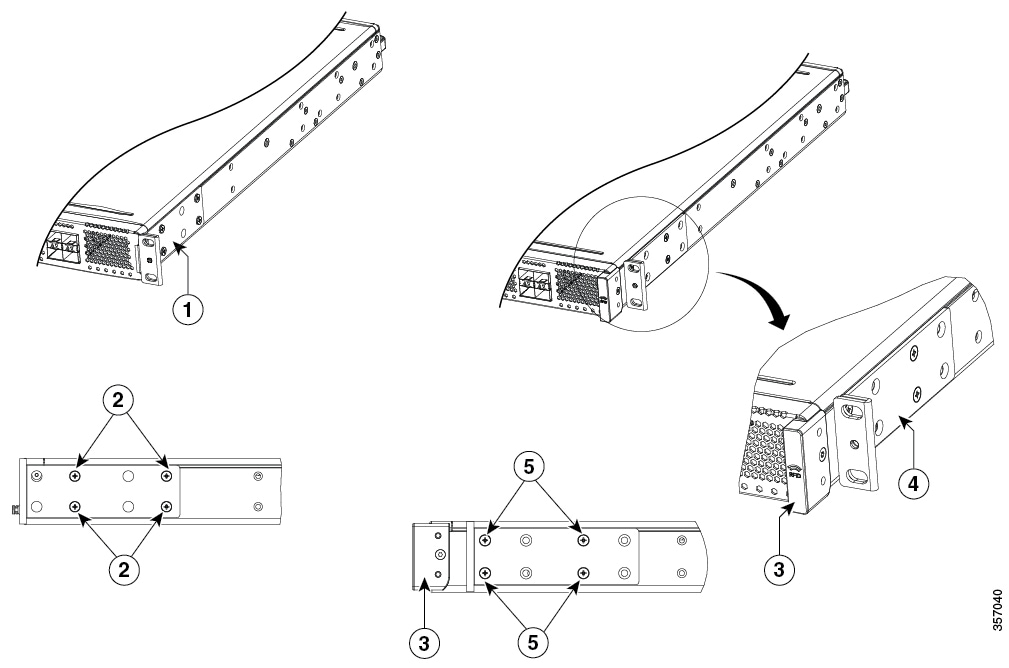
Figure 2. Rack mount bracket positions (I/O Side)

1

19-inch brackets; I/O-side flush (no RFID)

2

Screw locations for I/O-side flush (no RFID)

3

RFID

4 19-inch brackets; I/O-side recessed (with RFID)

5

Screw locations for I/O-side recessed (with RFID)

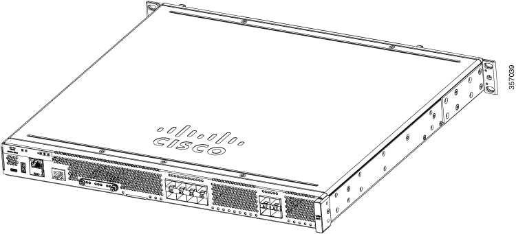
Figure 3. Install brackets for PS mounting

This image is for reference only.

1

19-inch brackets


Mid-mount the chassis

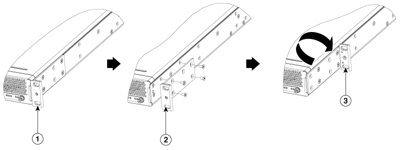
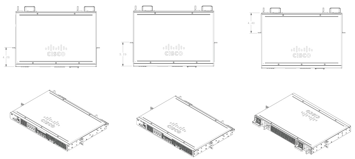
The Cisco 8400 Series Secure Routers can achieve many mounting depths by recessing or rotating the mounting bracket. In the example below, the I/O-Flush can be converted to middle-mount by rotating the bracket against the chassis to move the mounting flange away from the I/O face.

Figure 4. Securing the brackets

1

Forward-facing bracket

2

Screws securing the forward-facing bracket removed

3

Bracket reversed to rear-facing and reversed

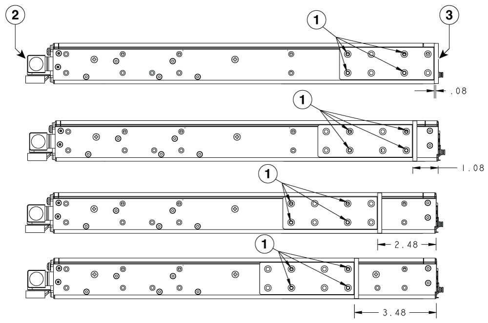
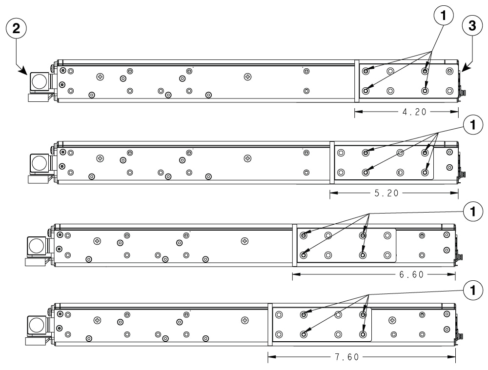
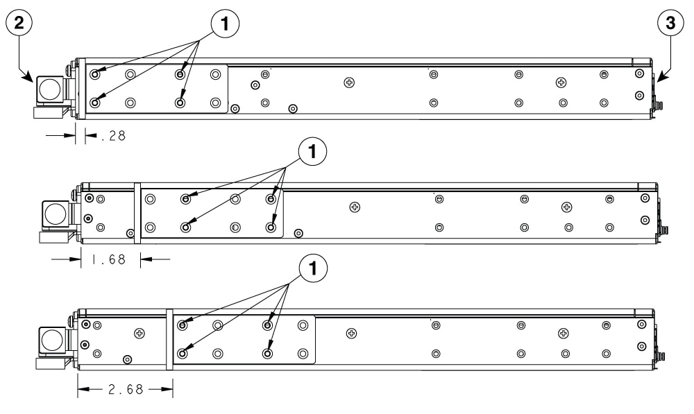
Following are all the possible mounting-depth options for the C8455-G2 and C8475-G2 (including I/O-flush and PSU-flush).

I/O Side Mounting

Figure 5. Brackets rotated flange towards I/O side
Figure 6. Brackets rotated flange away from I/O side

PSU Side Mounting

Figure 7. Brackets rotated flange towards PSU side
Figure 8. Brackets rotated flange away from PSU side

1

Securing Locations

2

PSU side

3

I/O side

The C8455-G2 is a shorter depth chassis and therefore has fewer options. The mid-mount depth options are shown below in isometric views.


Mount the chassis in a rack

After you attach the rack-mount brackets to the chassis, use screws to install the chassis in the rack.

Tip

For both the 19-inch EIA brackets and the 23-inch brackets, start the lower pair of screws first, and rest the brackets on the lower screws while you insert the upper pair of screws.

Tip

The screw slots in the brackets are spaced to line up with every second pair of screw holes in the rack. When the correct screw holes are used, the small threaded holes in the brackets line up with unused screw holes in the rack. If the small holes do not line up with the rack holes, you must raise or lower the brackets to the next rack hole.

Warning

To prevent bodily injury when mounting or servicing this unit in a rack, you must take special precautions to ensure that the system remains stable. The following guidelines are provided to ensure your safety:

  • This unit should be mounted at the bottom of the rack if it is the only unit in the rack.

  • When mounting this unit in a partially filled rack, load the rack from the bottom to the top with the heaviest component at the bottom of the rack.

Warning

Statement 1006—Chassis Warning for Rack-Mounting and Servicing

To prevent bodily injury when mounting or servicing this unit in a rack, you must take special precautions to ensure that the system remains stable. The following guidelines are provided to ensure your safety:

  • This unit should be mounted at the bottom of the rack if it is the only unit in the rack.

  • When mounting this unit in a partially filled rack, load the rack from the bottom to the top with the heaviest component at the bottom of the rack.

  • If the rack is provided with stabilizing devices, install the stabilizers before mounting or servicing the unit in the rack.

Warning

Statement 1032—Lifting the Chassis

To prevent personal injury or damage to the chassis, never attempt to lift or tilt the chassis using the handles on modules, such as power supplies, fans, or cards. These types of handles are not designed to support the weight of the unit.

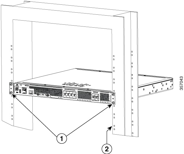
Figures below shows a typical rack mounting of a chassis in a rack.

Step1. Locate the desired position in the equipment rack.

Step2. Align the holes in the rack mount brackets with the mounting holes in the equipment frame.

Step3. Secure the device using mounting screws appropriate for your equipment frame. The rack mount brackets have been designed for #12 screws.

Step4. Tighten the screws to the appropriate torque value for your equipment

Figure 9. I/O Flush Mount in 19-inch Rack without RFID
Note

This image is for reference only.

1

Rack Mounting screws

2

Rack
Figure 10. I/O Flush Mount in 23-inch Rack without RFID
Note

This image is for reference only.

1

Rack Mounting screws

2

Rack


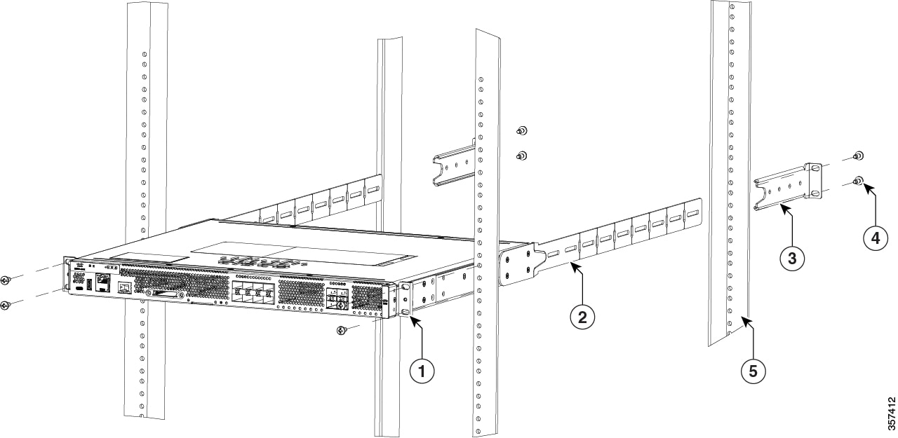
Four-post rack mounting

The four-post rack mounting is only supported on 19-inch equipment racks. The four-post mounting kit includes two standard 19-inch rack mount brackets and two rear support brackets. This kit does not include screws to secure the brackets to the frame.

Note

The four-post rack mounting is not supported on C8455-G2 router as it is a short-depth chassis.

  1. Assemble the two standard 19-inch rack mounting brackets in the desired location.

  2. Assemble the rear mount chassis brackets on the opposite ends of the router.

    Figure 11. Mounting the router in a four-post rack
    Note

    This image is for reference only.

    1

    19-inch mounting brackets

    2

    Screws (16 in total)

    3

    Rear mount chassis bracket

  3. Secure the router in the rack with the 19-inch rack mounting brackets.

  4. Slide the four-post mount rack brackets on to the rear mount brackets until they make contact with the rear frame. Finger tighten the screws securing the four-post mount rack brackets to the rear frame to verify the correct mounting location.

    Figure 12. Secure the router in a four-post rack
    Note

    This image is for reference only.

    1

    19-inch mounting brackets

    2

    Rear mount chassis bracket

    3

    Four-post mount rack bracket

    4

    Screws (8 in number, not included in the kit)

    5

    Rear frame

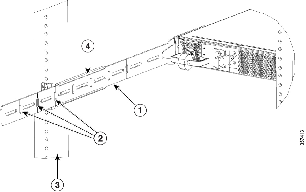
  5. The rear mount chassis bracket may extend beyond the rear frame. The bracket can be shortened by breaking off a length of the bracket at one of the vertical score lines. It is recommended that the bracket be shortened so that it does not protrude beyond the back rails and become a safety hazard. To shorten the bracket, mark the appropriate score line, remove the 4-point mount rack bracket, break the bracket at the designated score line, then re-assemble the four-post mount rack bracket.

    Figure 13. Brackets in a four-post rack
    Note

    This image is for reference only.

    1

    Rear mount chassis bracket in c-channel of four-post mount rack bracket

    2

    Vertical score lines

    3

    Rear frame

    4

    Four-post mount bracket

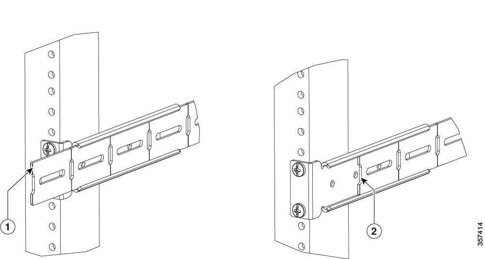
    Figure 14. Rear mount chassis bracket recesssed within the rear post
    Note

    This image is for reference only.

    1

    Rear mount chassis bracket protruding beyond the rear post

    2

    Rear mount chassis bracket recesssed within the rear post (intruding)

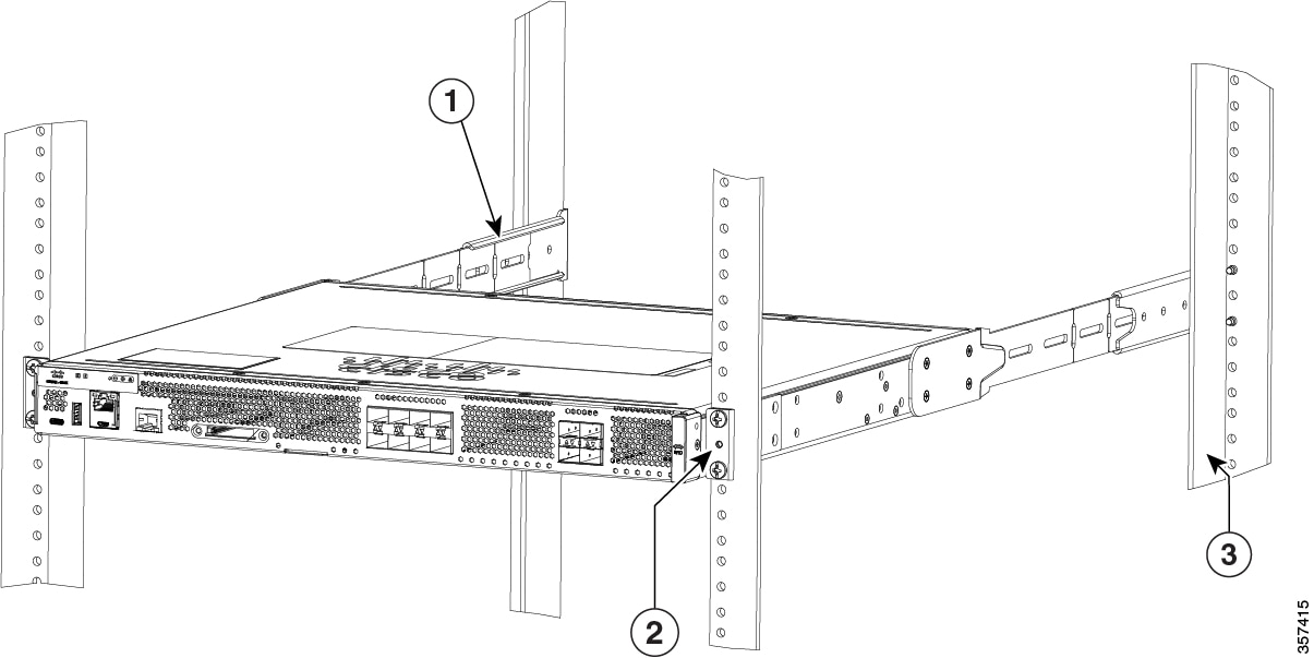
  6. Once everything is adjusted, tighten all the rack-mount screws starting at the front 19-inch mounting brackets, then securing the rear four-post brackets.

    Figure 15. Router secured in 19-inch mounting bracket
    Note

    This image is for reference only.

    1

    Rear mount chassis bracket in C-channel of four-post mount bracket shortened to be recesssed within the four-post mount rack bracket

    2

    19-inch mounting brackets

    3

    Rear frame

    4 Four-post mount rack bracket

Chassis grounding

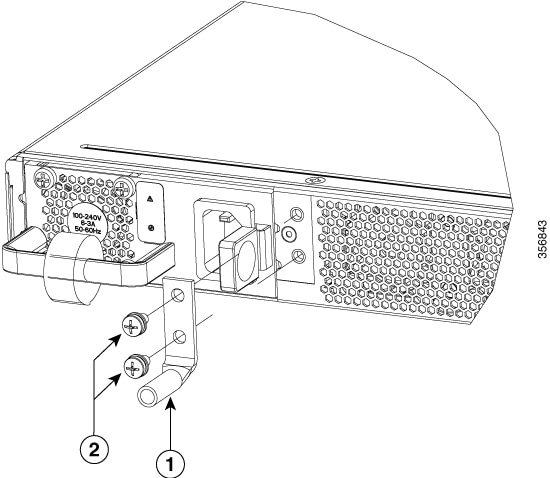
You must connect the chassis to a reliable earth ground; the ground wire must be installed in accordance with local electrical safety standards.

  • For grounding, use size 6 AWG (13 mm 2 ) copper wire and the ground lug provided in the accessory kit.

To install the ground connection for your router, perform the following steps:

Procedure

1.

Strip one end of the ground wire to the length required for the ground lug or terminal.

  • For the ground lug—approximately 0.75 inch (20 mm)

  • For user-provided ring terminal—as required

2.

Crimp the ground wire to the ground lug or ring terminal, using a crimp tool of the appropriate size.

3.

Attach the ground lug or ring terminal to the chassis . For a ground lug, use the two screws with captive locking washers provided. For a ring terminal, use one of the screws provided. Tighten the screws to a torque of 8 to 10 in-lb (0.9 to 1.1 N-m).

Figure 16. Chassis ground connection
4.

Connect the other end of the ground wire to a known reliable earth ground point at your site.

1

Ground lug

2

M4X0.7mm Screws