- Preface
- Product Overview
- Configuring the Router for the First Time
- Configuring a Supervisor Engine 720
- Configuring a Route Switch Processor 720
- Configuring NSF with SSO Supervisor Engine Redundancy
- ISSU and eFSU on Cisco 7600 Series Routers
- Configuring RPR and RPR+ Supervisor Engine Redundancy
- Configuring Interfaces
- Configuring a Supervisor Engine 32
- Configuring LAN Ports for Layer 2 Switching
- Configuring Flex Links
- Configuring EtherChannels
- Configuring VTP
- Configuring VLANs
- Configuring Private VLANs
- Configuring Cisco IP Phone Support
- Configuring IEEE 802.1Q Tunneling
- Configuring Layer 2 Protocol Tunneling
- Configuring L2TPv3
- Configuring STP and MST
- Configuring Optional STP Features
- Configuring Layer 3 Interfaces
- Configuring GTP-SLB IPV6 Support
- IP Subscriber Awareness over Ethernet
- Configuring UDE and UDLR
- Configuring Multiprotocol Label Switching on the PFC
- Configuring IPv4 Multicast VPN Support
- Configuring Multicast VPN Extranet Support
- Configuring IP Unicast Layer 3 Switching
- Configuring IPv6 Multicast PFC3 and DFC3 Layer 3 Switching
- Configuring IPv4 Multicast Layer 3 Switching
- Configuring MLDv2 Snooping for IPv6 Multicast Traffic
- Configuring IGMP Snooping for IPv4 Multicast Traffic
- Configuring PIM Snooping
- Configuring Network Security
- Understanding Cisco IOS ACL Support
- Configuring VRF aware 6RD Tunnels
- Configuring VLAN ACLs
- Private Hosts (Using PACLs)
- Configuring IPv6 PACL
- IPv6 First-Hop Security Features
- Configuring Online Diagnostics
- Configuring Denial of Service Protection
- Configuring DHCP Snooping
- Configuring Dynamic ARP Inspection
- Configuring Traffic Storm Control
- Unknown Unicast Flood Blocking
- Configuring PFC QoS
- Configuring PFC QoS Statistics Data Export
- Configuring MPLS QoS on the PFC
- Configuring LSM MLDP based MVPN Support
- Configuring IEEE 802.1X Port-Based Authentication
- Configuring IEEE 802.1ad
- Configuring Port Security
- Configuring UDLD
- Configuring NetFlow and NDE
- Configuring Local SPAN, RSPAN, and ERSPAN
- Configuring SNMP IfIndex Persistence
- Power Management and Environmental Monitoring
- Configuring Web Cache Services Using WCCP
- Using the Top N Utility
- Using the Layer 2 Traceroute Utility
- Configuring Bidirectional Forwarding and Detection over Switched Virtual Interface
- Configuring Call Home
- Configuring IPv6 Policy Based Routing
- Using the Mini Protocol Analyzer
- Configuring Resilient Ethernet Protocol
- Configuring Synchronous Ethernet
- Configuring Link State Tracking
- Configuring BGP PIC Edge and Core for IP and MPLS
- Configuring VRF aware IPv6 tunnels over IPv4 transport
- ISIS IPv4 Loop Free Alternate Fast Reroute (LFA FRR)
- Multicast Service Reflection
- Y.1731 Performance Monitoring
- Online Diagnostic Tests
- Acronyms
- Cisco IOS Release 15S Software Images
- Index
Configuring UDLD
This chapter describes how to configure the UniDirectional Link Detection (UDLD) protocol on the Cisco 7600 series routers.

Note For complete syntax and usage information for the commands used in this chapter, refer to the Cisco 7600 Series Routers Command References at this URL:
http://www.cisco.com/en/US/products/hw/routers/ps368/prod_command_reference_list.html
Understanding How UDLD Works
These sections describe how UDLD works:
UDLD Overview
The Cisco-proprietary UDLD protocol allows devices connected through fiber-optic or copper (for example, Category 5 cabling) Ethernet cables connected to LAN ports to monitor the physical configuration of the cables and detect when a unidirectional link exists. When a unidirectional link is detected, UDLD shuts down the affected LAN port and alerts the user. Unidirectional links can cause a variety of problems, including spanning tree topology loops.
UDLD is a Layer 2 protocol that works with the Layer 1 protocols to determine the physical status of a link. At Layer 1, autonegotiation takes care of physical signaling and fault detection. UDLD performs tasks that autonegotiation cannot perform, such as detecting the identities of neighbors and shutting down misconnected LAN ports. When you enable both autonegotiation and UDLD, Layer 1 and Layer 2 detections work together to prevent physical and logical unidirectional connections and the malfunctioning of other protocols.
A unidirectional link occurs whenever traffic transmitted by the local device over a link is received by the neighbor but traffic transmitted from the neighbor is not received by the local device. If one of the fiber strands in a pair is disconnected, as long as autonegotiation is active, the link does not stay up. In this case, the logical link is undetermined, and UDLD does not take any action. If both fibers are working normally at Layer 1, then UDLD at Layer 2 determines whether those fibers are connected correctly and whether traffic is flowing bidirectionally between the correct neighbors. This check cannot be performed by autonegotiation, because autonegotiation operates at Layer 1.
The Cisco 7600 series router periodically transmits UDLD packets to neighbor devices on LAN ports with UDLD enabled. If the packets are echoed back within a specific time frame and they are lacking a specific acknowledgment (echo), the link is flagged as unidirectional and the LAN port is shut down. Devices on both ends of the link must support UDLD in order for the protocol to successfully identify and disable unidirectional links.
Note![]() By default, UDLD is locally disabled on copper LAN ports to avoid sending unnecessary control traffic on this type of media since it is often used for access ports.
By default, UDLD is locally disabled on copper LAN ports to avoid sending unnecessary control traffic on this type of media since it is often used for access ports.
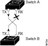
Figure 55-1 shows an example of a unidirectional link condition. Switch B successfully receives traffic from Switch A on the port. However, Switch A does not receive traffic from Switch B on the same port. UDLD detects the problem and disables the port.
Figure 55-1 Unidirectional Link
UDLD Aggressive Mode
UDLD aggressive mode is disabled by default. Configure UDLD aggressive mode only on point-to-point links between network devices that support UDLD aggressive mode. With UDLD aggressive mode enabled, when a port on a bidirectional link that has a UDLD neighbor relationship established stops receiving UDLD packets, UDLD tries to reestablish the connection with the neighbor. After eight failed retries, the port is disabled.
To prevent spanning tree loops, nonaggressive UDLD with the default interval of 15 seconds is fast enough to shut down a unidirectional link before a blocking port transitions to the forwarding state (with default spanning tree parameters).
When you enable UDLD aggressive mode, you receive additional benefits in the following situations:
- One side of a link has a port stuck (both Tx and Rx)
- One side of a link remains up while the other side of the link has gone down
In these cases, UDLD aggressive mode disables one of the ports on the link, which prevents traffic from being discarding.
Default UDLD Configuration
Table 55-1 shows the default UDLD configuration.
|
|
|
|---|---|
Restrictions for Configuring UDLD
Do not configure UDLD between peer interfaces of cross-connect as it tunnels the UDLD packets to the other end of the EVC.
Configuring UDLD
These sections describe how to configure UDLD:
- Enabling UDLD Globally
- Enabling UDLD on Individual LAN Interfaces
- Disabling UDLD on Fiber-Optic LAN Interfaces
- Configuring the UDLD Probe Message Interval
- Resetting Disabled LAN Interfaces
Enabling UDLD Globally
To enable UDLD globally on all fiber-optic LAN ports, perform this task:
|
|
|
|---|---|
Enables UDLD globally on fiber-optic LAN ports. Note This command only configures fiber-optic LAN ports. Individual LAN port configuration overrides the setting of this command. |
|
Enabling UDLD on Individual LAN Interfaces
To enable UDLD on individual LAN ports, perform this task:
|
|
|
|
|---|---|---|
Router(config)# interface type 1 slot/port |
||
Enables UDLD on a specific LAN port. Enter the aggressive keyword to enable aggressive mode. On a fiber-optic LAN port, this command overrides the udld enable global configuration command setting. |
||
Disables UDLD on a nonfiber-optic LAN port. Note On fiber-optic LAN ports, the no udld port command reverts the LAN port configuration to the udld enable global configuration command setting. |
||
|
1.type = ethernet, fastethernet, gigabitethernet, or tengigabitethernet |
Disabling UDLD on Fiber-Optic LAN Interfaces
To disable UDLD on individual fiber-optic LAN ports, perform this task:
|
|
|
|
|---|---|---|
Router(config)# interface type 2 slot/port |
||
Reverts to the udld enable global configuration command setting. Note This command is only supported on fiber-optic LAN ports. |
||
|
2.type = ethernet, fastethernet, gigabitethernet, or tengigabitethernet |
Configuring the UDLD Probe Message Interval
To configure the time between UDLD probe messages on ports that are in advertisement mode and are currently determined to be bidirectional, perform this task:
|
|
|
|
|---|---|---|
Configures the time between UDLD probe messages on ports that are in advertisement mode and are currently determined to be bidirectional; valid values are from 7 to 90 seconds. |
||
Router# show udld type 3 slot/number |
|
3.type = ethernet, fastethernet, gigabitethernet, or tengigabitethernet |
Resetting Disabled LAN Interfaces
To reset all LAN ports that have been shut down by UDLD, perform this task:
|
|
|
|---|---|
 Feedback