- Preface
- Product Overview
- Configuring the Router for the First Time
- Configuring a Supervisor Engine 720
- Configuring a Route Switch Processor 720
- Configuring NSF with SSO Supervisor Engine Redundancy
- ISSU and eFSU on Cisco 7600 Series Routers
- Configuring RPR and RPR+ Supervisor Engine Redundancy
- Configuring Interfaces
- Configuring a Supervisor Engine 32
- Configuring LAN Ports for Layer 2 Switching
- Configuring Flex Links
- Configuring EtherChannels
- Configuring VTP
- Configuring VLANs
- Configuring Private VLANs
- Configuring Cisco IP Phone Support
- Configuring IEEE 802.1Q Tunneling
- Configuring Layer 2 Protocol Tunneling
- Configuring L2TPv3
- Configuring STP and MST
- Configuring Optional STP Features
- Configuring Layer 3 Interfaces
- Configuring GTP-SLB IPV6 Support
- IP Subscriber Awareness over Ethernet
- Configuring UDE and UDLR
- Configuring Multiprotocol Label Switching on the PFC
- Configuring IPv4 Multicast VPN Support
- Configuring Multicast VPN Extranet Support
- Configuring IP Unicast Layer 3 Switching
- Configuring IPv6 Multicast PFC3 and DFC3 Layer 3 Switching
- Configuring IPv4 Multicast Layer 3 Switching
- Configuring MLDv2 Snooping for IPv6 Multicast Traffic
- Configuring IGMP Snooping for IPv4 Multicast Traffic
- Configuring PIM Snooping
- Configuring Network Security
- Understanding Cisco IOS ACL Support
- Configuring VRF aware 6RD Tunnels
- Configuring VLAN ACLs
- Private Hosts (Using PACLs)
- Configuring IPv6 PACL
- IPv6 First-Hop Security Features
- Configuring Online Diagnostics
- Configuring Denial of Service Protection
- Configuring DHCP Snooping
- Configuring Dynamic ARP Inspection
- Configuring Traffic Storm Control
- Unknown Unicast Flood Blocking
- Configuring PFC QoS
- Configuring PFC QoS Statistics Data Export
- Configuring MPLS QoS on the PFC
- Configuring LSM MLDP based MVPN Support
- Configuring IEEE 802.1X Port-Based Authentication
- Configuring IEEE 802.1ad
- Configuring Port Security
- Configuring UDLD
- Configuring NetFlow and NDE
- Configuring Local SPAN, RSPAN, and ERSPAN
- Configuring SNMP IfIndex Persistence
- Power Management and Environmental Monitoring
- Configuring Web Cache Services Using WCCP
- Using the Top N Utility
- Using the Layer 2 Traceroute Utility
- Configuring Bidirectional Forwarding and Detection over Switched Virtual Interface
- Configuring Call Home
- Configuring IPv6 Policy Based Routing
- Using the Mini Protocol Analyzer
- Configuring Resilient Ethernet Protocol
- Configuring Synchronous Ethernet
- Configuring Link State Tracking
- Configuring BGP PIC Edge and Core for IP and MPLS
- Configuring VRF aware IPv6 tunnels over IPv4 transport
- ISIS IPv4 Loop Free Alternate Fast Reroute (LFA FRR)
- Multicast Service Reflection
- Y.1731 Performance Monitoring
- Online Diagnostic Tests
- Acronyms
- Cisco IOS Release 15S Software Images
- Index
- Understanding DAI
- Default DAI Configuration
- DAI Configuration Guidelines and Restrictions
- Configuring DAI
- DAI Configuration Samples
Configuring Dynamic ARP Inspection
This chapter describes how to configure dynamic Address Resolution Protocol (ARP) inspection (DAI) on the Cisco 7600 series router.

Note For complete syntax and usage information for the commands used in this chapter, refer to the Cisco 7600 Series Routers Command References at this URL:
http://www.cisco.com/en/US/products/hw/routers/ps368/prod_command_reference_list.html
Understanding DAI
These sections describe how DAI helps prevent ARP spoofing attacks:
Understanding ARP
ARP provides IP communication within a Layer 2 broadcast domain by mapping an IP address to a MAC address. For example, Host B wants to send information to Host A but does not have the MAC address of Host A in its ARP cache. Host B generates a broadcast message for all hosts within the broadcast domain to obtain the MAC address associated with the IP address of Host A. All hosts within the broadcast domain receive the ARP request, and Host A responds with its MAC address.
Understanding ARP Spoofing Attacks
ARP spoofing attacks and ARP cache poisoning can occur because ARP allows a gratuitous reply from a host even if an ARP request was not received. After the attack, all traffic from the device under attack flows through the attacker’s computer and then to the router, switch, or host.
An ARP spoofing attack can target hosts, switches, and routers connected to your Layer 2 network by poisoning the ARP caches of systems connected to the subnet and by intercepting traffic intended for other hosts on the subnet. Figure 45-1 shows an example of ARP cache poisoning.
Figure 45-1 ARP Cache Poisoning
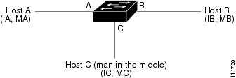
Hosts A, B, and C are connected to the router on interfaces A, B and C, all of which are on the same subnet. Their IP and MAC addresses are shown in parentheses; for example, Host A uses IP address IA and MAC address MA. When Host A needs to communicate to Host B at the IP layer, it broadcasts an ARP request for the MAC address associated with IP address IB. When the router and Host B receive the ARP request, they populate their ARP caches with an ARP binding for a host with the IP address IA and a MAC address MA; for example, IP address IA is bound to MAC address MA. When Host B responds, the router and Host A populate their ARP caches with a binding for a host with the IP address IB and the MAC address MB.
Host C can poison the ARP caches of the router, Host A, and Host B by broadcasting forged ARP responses with bindings for a host with an IP address of IA (or IB) and a MAC address of MC. Hosts with poisoned ARP caches use the MAC address MC as the destination MAC address for traffic intended for IA or IB. This means that Host C intercepts that traffic. Because Host C knows the true MAC addresses associated with IA and IB, it can forward the intercepted traffic to those hosts by using the correct MAC address as the destination. Host C has inserted itself into the traffic stream from Host A to Host B, which is the topology of the classic man-in-the middle attack.
Understanding DAI and ARP Spoofing Attacks
DAI is a security feature that validates ARP packets in a network. DAI intercepts, logs, and discards ARP packets with invalid IP-to-MAC address bindings. This capability protects the network from some man-in-the-middle attacks.
DAI ensures that only valid ARP requests and responses are relayed. The router performs these activities:
- Intercepts all ARP requests and responses on untrusted ports
- Verifies that each of these intercepted packets has a valid IP-to-MAC address binding before updating the local ARP cache or before forwarding the packet to the appropriate destination
- Drops invalid ARP packets
DAI determines the validity of an ARP packet based on valid IP-to-MAC address bindings stored in a trusted database, the DHCP snooping binding database. This database is built by DHCP snooping if DHCP snooping is enabled on the VLANs and on the router. If the ARP packet is received on a trusted interface, the router forwards the packet without any checks. On untrusted interfaces, the router forwards the packet only if it is valid.
DAI can validate ARP packets against user-configured ARP access control lists (ACLs) for hosts with statically configured IP addresses (see “Applying ARP ACLs for DAI Filtering” section). The router logs dropped packets (see the “Logging of Dropped Packets” section).
You can configure DAI to drop ARP packets when the IP addresses in the packets are invalid or when the MAC addresses in the body of the ARP packets do not match the addresses specified in the Ethernet header (see the “Enabling Additional Validation” section).
Interface Trust States and Network Security
DAI associates a trust state with each interface on the router. Packets arriving on trusted interfaces bypass all DAI validation checks, and those arriving on untrusted interfaces undergo the DAI validation process.
In a typical network configuration, you configure all router ports connected to host ports as untrusted and configure all router ports connected to routers as trusted. With this configuration, all ARP packets entering the network from a given router bypass the security check. No other validation is needed at any other place in the VLAN or in the network. You configure the trust setting by using the ip arp inspection trust interface configuration command.

Caution Use the trust state configuration carefully. Configuring interfaces as untrusted when they should be trusted can result in a loss of connectivity.
In Figure 45-2, assume that both Router A and Router B are running DAI on the VLAN that includes Host 1 and Host 2. If Host 1 and Host 2 acquire their IP addresses from the DHCP server connected to Router A, only Router A binds the IP-to-MAC address of Host 1. Therefore, if the interface between Router A and Router B is untrusted, the ARP packets from Host 1 are dropped by Router B. Connectivity between Host 1 and Host 2 is lost.
Figure 45-2 ARP Packet Validation on a VLAN Enabled for DAI
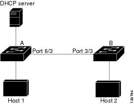
Configuring interfaces to be trusted when they are actually untrusted leaves a security hole in the network. If Router A is not running DAI, Host 1 can easily poison the ARP cache of Router B (and Host 2, if the link between the routers is configured as trusted). This condition can occur even though Router B is running DAI.
DAI ensures that hosts (on untrusted interfaces) connected to a router running DAI do not poison the ARP caches of other hosts in the network. However, DAI does not prevent hosts in other portions of the network from poisoning the caches of the hosts that are connected to a router running DAI.
In cases in which some routers in a VLAN run DAI and other routers do not, configure the interfaces connecting such routers as untrusted. However, to validate the bindings of packets from routers where DAI is not configured, configure ARP ACLs on the router running DAI. When you cannot determine such bindings, isolate routers running DAI at Layer 3 from routers not running DAI. For configuration information, see the “Sample Two: One Switch Supports DAI” section.
Note Depending on the setup of the DHCP server and the network, it might not be possible to validate a given ARP packet on all routers in the VLAN.
Rate Limiting of ARP Packets
The router performs DAI validation checks, which rate limits incoming ARP packets to prevent a denial-of-service attack. By default, the rate for untrusted interfaces is 15 packets per second (pps). Trusted interfaces are not rate limited. You can change this setting by using the ip arp inspection limit interface configuration command.
When the rate of incoming ARP packets exceeds the configured limit, the router places the port in the error-disabled state. The port remains in that state until you intervene. You can use the errdisable recovery global configuration command to enable error disable recovery so that ports automatically emerge from this state after a specified timeout period.
For configuration information, see the “Configuring ARP Packet Rate Limiting” section.
Relative Priority of ARP ACLs and DHCP Snooping Entries
DAI uses the DHCP snooping binding database for the list of valid IP-to-MAC address bindings.
ARP ACLs take precedence over entries in the DHCP snooping binding database. The router uses ACLs only if you configure them by using the ip arp inspection filter global configuration command. The router first compares ARP packets to user-configured ARP ACLs. If the ARP ACL denies the ARP packet, the router also denies the packet even if a valid binding exists in the database populated by DHCP snooping.
Logging of Dropped Packets
When the router drops a packet, it places an entry in the log buffer and then generates system messages on a rate-controlled basis. After the message is generated, the router clears the entry from the log buffer. Each log entry contains flow information, such as the receiving VLAN, the port number, the source and destination IP addresses, and the source and destination MAC addresses.
You use the ip arp inspection log-buffer global configuration command to configure the number of entries in the buffer and the number of entries needed in the specified interval to generate system messages. You specify the type of packets that are logged by using the ip arp inspection vlan logging global configuration command. For configuration information, see the “Configuring DAI Logging” section.
Default DAI Configuration
Table 45-1 shows the default DAI configuration.
DAI Configuration Guidelines and Restrictions
When configuring DAI, follow these guidelines and restrictions:
- DAI is an ingress security feature; it does not perform any egress checking.
- DAI is not effective for hosts connected to routers that do not support DAI or that do not have this feature enabled. Because man-in-the-middle attacks are limited to a single Layer 2 broadcast domain, separate the domain with DAI checks from the one with no checking. This action secures the ARP caches of hosts in the domain enabled for DAI.
- DAI depends on the entries in the DHCP snooping binding database to verify IP-to-MAC address bindings in incoming ARP requests and ARP responses. Make sure to enable DHCP snooping to permit ARP packets that have dynamically assigned IP addresses. For configuration information, see Chapter44, “Configuring DHCP Snooping”
- When DHCP snooping is disabled or in non-DHCP environments, use ARP ACLs to permit or to deny packets.
- DAI is supported on access ports, trunk ports, EtherChannel ports, and private VLAN ports.
- A physical port can join an EtherChannel port channel only when the trust state of the physical port and the channel port match. Otherwise, the physical port remains suspended in the port channel. A port channel inherits its trust state from the first physical port that joins the channel. Consequently, the trust state of the first physical port need not match the trust state of the channel.
Conversely, when you change the trust state on the port channel, the router configures a new trust state on all the physical ports that comprise the channel.
- The operating rate for the port channel is cumulative across all the physical ports within the channel. For example, if you configure the port channel with an ARP rate-limit of 400 pps, all the interfaces combined on the channel receive an aggregate 400 pps. The rate of incoming ARP packets on EtherChannel ports is equal to the sum of the incoming rate of packets from all the channel members. Configure the rate limit for EtherChannel ports only after examining the rate of incoming ARP packets on the channel-port members.
The rate of incoming packets on a physical port is checked against the port-channel configuration rather than the physical-ports configuration. The rate-limit configuration on a port channel is independent of the configuration on its physical ports.
If the EtherChannel receives more ARP packets than the configured rate, the channel (including all physical ports) is placed in the error-disabled state.
- Make sure to limit the rate of ARP packets on incoming trunk ports. Configure trunk ports with higher rates to reflect their aggregation and to handle packets across multiple DAI-enabled VLANs. You also can use the ip arp inspection limit none interface configuration command to make the rate unlimited. A high rate-limit on one VLAN can cause a denial-of-service attack to other VLANs when the software places the port in the error-disabled state.
- Cisco IOS Release 12.2(33)SRD2 provides support for ARP Scale to 512k (static or dynamic)—This feature is supported with 3CXL versions of the Cisco 7600 Series ES+ line cards with RSP720-3CXL-GE with 2G SP memory or RSP720-3CXL-10GE with 2G SP memory. Use the following guidelines:
– If you are using an Switched Virtual Interface (SVI) as a Layer 3 interface, you need to disable MAC Learning.
– Use the mls cef maximum-routes command to increase Cisco Express Forwarding (CEF) holding capacity for IPv4.
Configuring DAI
These sections describe how to configure DAI:
- Enabling DAI on VLANs
- Configuring the DAI Interface Trust State
- Applying ARP ACLs for DAI Filtering
- Configuring ARP Packet Rate Limiting
- Enabling DAI Error-Disabled Recovery
- Enabling Additional Validation
- Configuring DAI Logging
- Displaying DAI Information
Enabling DAI on VLANs
To enable DAI on VLANs, perform this task:
You can enable DAI on a single VLAN or a range of VLANs:
- To enable a single VLAN, enter a single VLAN number.
- To enable a range of VLANs, enter a dash-separated pair of VLAN numbers.
- You can enter a comma-separated list of VLAN numbers and dash-separated pairs of VLAN numbers.
This example shows how to enable DAI on VLANs 10 through 12:
This example shows another way to enable DAI on VLANs 10 through 12:
This example shows how to enable DAI on VLANs 10 through 12 and VLAN 15:
Configuring the DAI Interface Trust State
The router does not check ARP packets that it receives from the other router on the trusted interface. It simply forwards the packets.
On untrusted interfaces, the router intercepts all ARP requests and responses. It verifies that the intercepted packets have valid IP-to-MAC address bindings before updating the local cache and before forwarding the packet to the appropriate destination. The router drops invalid packets and logs them in the log buffer according to the logging configuration specified with the ip arp inspection vlan logging global configuration command. For more information, see the “Configuring DAI Logging” section .
To configure the DAI interface trust state, perform this task:
Router(config)# interface { type 1 slot/port | port-channel number } |
Specifies the interface connected to another router, and enter interface configuration mode. |
|
Configures the connection between routers as trusted (default: untrusted). |
||
This example shows how to configure Fast Ethernet port 5/12 as trusted:
Applying ARP ACLs for DAI Filtering
Note See the Cisco 7600 Series Router Cisco IOS Command Reference, for information about the arp access-list command.
To apply an ARP ACL, perform this task:
Router# ip arp inspection filter arp_acl_name vlan { vlan_ID | vlan_range } [static] |
||
Router(config)# do show ip arp inspection vlan { vlan_ID | vlan_range } |
When applying ARP ACLs, note the following information:
– To specify a single VLAN, enter a single VLAN number.
– To specify a range of VLANs, enter a dash-separated pair of VLAN numbers.
– You can enter a comma-separated list of VLAN numbers and dash-separated pairs of VLAN numbers.
- (Optional) Specify static to treat implicit denies in the ARP ACL as explicit denies and to drop packets that do not match any previous clauses in the ACL. DHCP bindings are not used.
If you do not specify this keyword, it means that there is no explicit deny in the ACL that denies the packet, and DHCP bindings determine whether a packet is permitted or denied if the packet does not match any clauses in the ACL.
- ARP packets containing only IP-to-MAC address bindings are compared against the ACL. Packets are permitted only if the access list permits them.
This example shows how to apply an ARP ACL named example_arp_acl to VLANs 10 through 12 and VLAN 15:
Configuring ARP Packet Rate Limiting
When DAI is enabled, the router performs ARP packet validation checks, which makes the router vulnerable to an ARP-packet denial-of-service attack. ARP packet rate limiting can prevent an ARP-packet denial-of-service attack.
To configure ARP packet rate limiting on a port, perform this task:
Router(config)# interface { type 2 slot/port | port-channel number } |
||
Router(config-if)# ip arp inspection limit { rate pps [ burst interval seconds ] | none } |
||
When configuring ARP packet rate limiting, note the following information:
- The default rate is 15 pps on untrusted interfaces and unlimited on trusted interfaces.
- For rate pps , specify an upper limit for the number of incoming packets processed per second. The range is 0 to 2048 pps.
- The rate none keywords specify that there is no upper limit for the rate of incoming ARP packets that can be processed.
- (Optional) For burst interval seconds (default is 1), specify the consecutive interval, in seconds, over which the interface is monitored for a high rate of ARP packets.The range is 1 to 15.
- When the rate of incoming ARP packets exceeds the configured limit, the router places the port in the error-disabled state. The port remains in the error-disabled state until you enable error-disabled recovery, which allows the port to emerge from the error-disabled state after a specified timeout period.
- Unless you configure a rate-limiting value on an interface, changing the trust state of the interface also changes its rate-limiting value to the default value for the configured trust state. After you configure the rate-limiting value, the interface retains the rate-limiting value even when you change its trust state. If you enter the no ip arp inspection limit interface configuration command, the interface reverts to its default rate-limiting value.
- For configuration guidelines about limiting the rate of incoming ARP packets on trunk ports and EtherChannel ports, see the “DAI Configuration Guidelines and Restrictions” section.
This example shows how to configure ARP packet rate limiting on Fast Ethernet port 5/14:
Enabling DAI Error-Disabled Recovery
To enable DAI error disabled recovery, perform this task:
This example shows how to enable DAI error disabled recovery:
Enabling Additional Validation
DAI intercepts, logs, and discards ARP packets with invalid IP-to-MAC address bindings. You can enable additional validation on the destination MAC address, the sender and target IP addresses, and the source MAC address.
To enable additional validation, perform this task:
Router(config)# ip arp inspection validate {[ dst-mac ] [ ip ] [ src-mac ]} |
||
Router(config)# no ip arp inspection validate {[ dst-mac ] [ ip ] [ src-mac ]} |
||
When enabling additional validation, note the following information:
- You must specify at least one of the keywords.
- Each ip arp inspection validate command overrides the configuration from any previous commands. If an ip arp inspection validate command enables src and dst mac validations, and a second ip arp inspection validate command enables IP validation only, the src and dst mac validations are disabled as a result of the second command.
- These are the additional validations:
– dst-mac —Checks the destination MAC address in the Ethernet header against the target MAC address in ARP body. This check is performed for ARP responses. When enabled, packets with different MAC addresses are classified as invalid and are dropped.
– ip —Checks the ARP body for invalid and unexpected IP addresses. Addresses include 0.0.0.0, 255.255.255.255, and all IP multicast addresses. Sender IP addresses are checked in all ARP requests and responses, and target IP addresses are checked only in ARP responses.
– src-mac —Checks the source MAC address in the Ethernet header against the sender MAC address in the ARP body. This check is performed on both ARP requests and responses. When enabled, packets with different MAC addresses are classified as invalid and are dropped.
This example shows how to enable src-mac additional validation:
This example shows how to enable dst-mac additional validation:
This example shows how to enable ip additional validation:
This example shows how to enable src-mac and dst-mac additional validation:
This example shows how to enable src-mac, dst-mac, and ip additional validation:
DAI Logging Overview
When DAI drops a packet, it places an entry in the log buffer and then generates system messages on a rate-controlled basis. After the message is generated, DAI clears the entry from the log buffer. Each log entry contains flow information, such as the receiving VLAN, the port number, the source and destination IP addresses, and the source and destination MAC addresses.
A log-buffer entry can represent more than one packet. For example, if an interface receives many packets on the same VLAN with the same ARP parameters, DAI combines the packets as one entry in the log buffer and generates a single system message for the entry.
If the log buffer overflows, it means that a log event does not fit into the log buffer, and the display for the show ip arp inspection log privileged EXEC command is affected. Two dashes (“--”) appear instead of data except for the packet count and the time. No other statistics are provided for the entry. If you see this entry in the display, increase the number of entries in the log buffer or increase the logging rate.
Configuring the DAI Logging Buffer Size
To configure the DAI logging buffer size, perform this task:
Configures the DAI logging buffer size (range is 0 to 1024). |
||
Router(config)# do show ip arp inspection log | include Size |
This example shows how to configure the DAI logging buffer for 64 messages:
Configuring the DAI Logging System Messages
To configure the DAI logging system messages, perform this task:
When configuring the DAI logging system messages, note the following information:
- For logs number_of_messages (default is 5), the range is 0 to 1024. A 0 value means that the entry is placed in the log buffer, but a system message is not generated.
- For interval length_in_seconds (default is 1), the range is 0 to 86400 seconds (1 day). A 0 value means that a system message is immediately generated (and the log buffer is always empty). An interval setting of 0 overrides a log setting of 0.
- System messages are sent at the rate of number_of_messages per length_in_seconds .
This example shows how to configure DAI logging to send 12 messages every 2 seconds:
This example shows how to configure DAI logging to send 20 messages every 60 seconds.
Configuring DAI Log Filtering
To configure DAI log filtering, perform this task:
When configuring the DAI log filtering, note the following information:
- By default, all denied packets are logged.
- For vlan_range , you can specify a single VLAN or a range of VLANs:
– To specify a single VLAN, enter a single VLAN number.
– To specify a range of VLANs, enter a dash-separated pair of VLAN numbers.
– You can enter a comma-separated list of VLAN numbers and dash-separated pairs of VLAN numbers.
- acl-match matchlog—Logs packets based on the DAI ACL configuration. If you specify the matchlog keyword in this command and the log keyword in the permit or deny ARP access-list configuration command, ARP packets permitted or denied by the ACL are logged.
- acl-match none —Does not log packets that match ACLs.
- dhcp-bindings all—Logs all packets that match DHCP bindings.
- dhcp-bindings none—Does not log packets that match DHCP bindings.
- dhcp-bindings permit—Logs DHCP-binding permitted packets.
This example shows how to configure the DAI log filtering for VLAN 100 not to log packets that match ACLs:
Displaying DAI Information
To display DAI information, use the privileged EXEC commands described in Table 45-2 .
To clear or display DAI statistics, use the privileged EXEC commands in Table 45-3 .
For the show ip arp inspection statistics command, the router increments the number of forwarded packets for each ARP request and response packet on a trusted DAI port. The router increments the number of ACL-permitted or DHCP-permitted packets for each packet that is denied by source MAC, destination MAC, or IP validation checks, and the router increments the appropriate failure count.
To clear or display DAI logging information, use the privileged EXEC commands in Table 45-4 :
DAI Configuration Samples
This section includes these samples:
Sample One: Two Switches Support DAI
This procedure shows how to configure DAI when two routers support this feature. Host 1 is connected to Router A, and Host 2 is connected to Router B as shown in Figure 45-2. Both routers are running DAI on VLAN 1 where the hosts are located. A DHCP server is connected to Router A. Both hosts acquire their IP addresses from the same DHCP server. Router A has the bindings for Host 1 and Host 2, and Router B has the binding for Host 2. Router A Fast Ethernet port 6/3 is connected to the Router B Fast Ethernet port 3/3.
Note • DAI depends on the entries in the DHCP snooping binding database to verify IP-to-MAC address bindings in incoming ARP requests and ARP responses. Make sure to enable DHCP snooping to permit ARP packets that have dynamically assigned IP addresses. For configuration information, see Chapter44, “Configuring DHCP Snooping”
- This configuration does not work if the DHCP server is moved from Router A to a different location.
- To ensure that this configuration does not compromise security, configure Fast Ethernet port 6/3 on Router A and Fast Ethernet port 3/3 on Router B as trusted.
Configuring Router A
To enable DAI and configure Fast Ethernet port 6/3 on Router A as trusted, follow these steps:
Step 1 Verify the connection between switches Router A and Router B:
Step 2 Enable DAI on VLAN 1 and verify the configuration:
Step 3 Configure Fast Ethernet port 6/3 as trusted:
Step 5 Check the statistics before and after DAI processes any packets:
If Host 1 then sends out two ARP requests with an IP address of 1.1.1.2 and a MAC address of 0002.0002.0002, both requests are permitted, as reflected in the following statistics:
If Host 1 then tries to send an ARP request with an IP address of 1.1.1.3, the packet is dropped and an error message is logged:
00:12:08: %SW_DAI-4-DHCP_SNOOPING_DENY: 2 Invalid ARPs (Req) on Fa6/4, vlan 1.([0002.0002.0002/1.1.1.3/0000.0000.0000/0.0.0.0/02:42:35 UTC Tue Jul 10 2001])
The statistics will display as follows:
Configuring Router B
To enable DAI and configure Fast Ethernet port 3/3 on Router B as trusted, follow these steps:
Step 1 Verify the connectivity:
Step 2 Enable DAI on VLAN 1, and verify the configuration:
Step 3 Configure Fast Ethernet port 3/3 as trusted:
Step 4 Verify the list of DHCP snooping bindings:
Step 5 Check the statistics before and after DAI processes any packets:
If Host 2 then sends out an ARP request with the IP address 1.1.1.1 and the MAC address 0001.0001.0001, the packet is forwarded and the statistics are updated appropriately:
If Host 2 attempts to send an ARP request with the IP address 1.1.1.2, DAI drops the request and logs a system message:
00:18:08: %SW_DAI-4-DHCP_SNOOPING_DENY: 1 Invalid ARPs (Req) on Fa3/4, vlan 1.([0001.0001.0001/1.1.1.2/0000.0000.0000/0.0.0.0/01:53:21 UTC Fri May 23 2003])
The statistics display as follows:
Sample Two: One Switch Supports DAI
This procedure shows how to configure DAI when Router B shown in Figure 45-2 does not support DAI or DHCP snooping.
If switch Router B does not support DAI or DHCP snooping, configuring Fast Ethernet port 6/3 on Router A as trusted creates a security hole because both Router A and Host 1 could be attacked by either Router B or Host 2.
To prevent this possibility, you must configure Fast Ethernet port 6/3 on Router A as untrusted. To permit ARP packets from Host 2, you must set up an ARP ACL and apply it to VLAN 1. If the IP address of Host 2 is not static, which would make it impossible to apply the ACL configuration on Router A, you must separate Router A from Router B at Layer 3 and use a router to route packets between them.
To set up an ARP ACL on switch Router A, follow these steps:
Step 1 Configure the access list to permit the IP address 1.1.1.1 and the MAC address 0001.0001.0001, and verify the configuration:
Step 2 Apply the ACL to VLAN 1, and verify the configuration:
Step 3 Configure Fast Ethernet port 6/3 as untrusted, and verify the configuration:
When Host 2 sends 5 ARP requests through Fast Ethernet port 6/3 on Router A and a “get” is permitted by Router A, the statistics are updated appropriately:
 Feedback