- Preface
- Product Overview
- Configuring the Router for the First Time
- Configuring a Supervisor Engine 720
- Configuring a Route Switch Processor 720
- Configuring NSF with SSO Supervisor Engine Redundancy
- ISSU and eFSU on Cisco 7600 Series Routers
- Configuring RPR and RPR+ Supervisor Engine Redundancy
- Configuring Interfaces
- Configuring a Supervisor Engine 32
- Configuring LAN Ports for Layer 2 Switching
- Configuring Flex Links
- Configuring EtherChannels
- Configuring VTP
- Configuring VLANs
- Configuring Private VLANs
- Configuring Cisco IP Phone Support
- Configuring IEEE 802.1Q Tunneling
- Configuring Layer 2 Protocol Tunneling
- Configuring L2TPv3
- Configuring STP and MST
- Configuring Optional STP Features
- Configuring Layer 3 Interfaces
- Configuring GTP-SLB IPV6 Support
- IP Subscriber Awareness over Ethernet
- Configuring UDE and UDLR
- Configuring Multiprotocol Label Switching on the PFC
- Configuring IPv4 Multicast VPN Support
- Configuring Multicast VPN Extranet Support
- Configuring IP Unicast Layer 3 Switching
- Configuring IPv6 Multicast PFC3 and DFC3 Layer 3 Switching
- Configuring IPv4 Multicast Layer 3 Switching
- Configuring MLDv2 Snooping for IPv6 Multicast Traffic
- Configuring IGMP Snooping for IPv4 Multicast Traffic
- Configuring PIM Snooping
- Configuring Network Security
- Understanding Cisco IOS ACL Support
- Configuring VRF aware 6RD Tunnels
- Configuring VLAN ACLs
- Private Hosts (Using PACLs)
- Configuring IPv6 PACL
- IPv6 First-Hop Security Features
- Configuring Online Diagnostics
- Configuring Denial of Service Protection
- Configuring DHCP Snooping
- Configuring Dynamic ARP Inspection
- Configuring Traffic Storm Control
- Unknown Unicast Flood Blocking
- Configuring PFC QoS
- Configuring PFC QoS Statistics Data Export
- Configuring MPLS QoS on the PFC
- Configuring LSM MLDP based MVPN Support
- Configuring IEEE 802.1X Port-Based Authentication
- Configuring IEEE 802.1ad
- Configuring Port Security
- Configuring UDLD
- Configuring NetFlow and NDE
- Configuring Local SPAN, RSPAN, and ERSPAN
- Configuring SNMP IfIndex Persistence
- Power Management and Environmental Monitoring
- Configuring Web Cache Services Using WCCP
- Using the Top N Utility
- Using the Layer 2 Traceroute Utility
- Configuring Bidirectional Forwarding and Detection over Switched Virtual Interface
- Configuring Call Home
- Configuring IPv6 Policy Based Routing
- Using the Mini Protocol Analyzer
- Configuring Resilient Ethernet Protocol
- Configuring Synchronous Ethernet
- Configuring Link State Tracking
- Configuring BGP PIC Edge and Core for IP and MPLS
- Configuring VRF aware IPv6 tunnels over IPv4 transport
- ISIS IPv4 Loop Free Alternate Fast Reroute (LFA FRR)
- Multicast Service Reflection
- Y.1731 Performance Monitoring
- Online Diagnostic Tests
- Acronyms
- Cisco IOS Release 15S Software Images
- Index
- Understanding How IPv4 Multicast Layer3 Switching Works
- Source-Specific Multicast with IGMPv3, IGMP v3lite, and URD
- Enabling IPv4 Multicast Routing Globally
- Enabling IPv4 PIM on Layer3 Interfaces
- Enabling IP Multicast Layer 3 Switching Globally
- Enabling IP Multicast Layer3 Switching on Layer3 Interfaces
- Configuring the Replication Mode
- Enabling Local Egress Replication
- Configuring the Layer3 Switching Global Threshold
- Enabling Installation of Directly Connected Subnets
- Specifying the Flow Statistics Message Interval
- Configuring ACL-Based Filtering of RPF Failures
- Validating the Rate-Limiter Status
- Displaying IPv4 Multicast Layer3 Hardware Switching Summary
- Displaying the IPv4 Multicast Routing Table
- Displaying IPv4 Multicast Layer3 Switching Statistics
Configuring IPv4 Multicast Layer 3 Switching
This chapter describes how to configure IPv4 multicast Layer 3 switching on the Cisco 7600 series routers.

Note For complete syntax and usage information for the commands used in this chapter, refer to these publications:
http://www.cisco.com/en/US/products/hw/routers/ps368/prod_command_reference_list.html
http://www.cisco.com/univercd/cc/td/doc/product/software/ios122/122cgcr/index.htm
This chapter consists of these sections:
- Understanding How IPv4 Multicast Layer 3 Switching Works
- Understanding How IPv4 Bidirectional PIM Works
- Default IPv4 Multicast Layer 3 Switching Configuration
- IPv4 Multicast Layer 3 Switching Configuration Guidelines and Restrictions
- Configuring IPv4 Multicast Layer 3 Switching
- Configuring IPv4 Bidirectional PIM
Understanding How IPv4 Multicast Layer 3 Switching Works
These sections describe how IPv4 multicast Layer 3 switching works:
- IPv4 Multicast Layer 3 Switching Overview
- Multicast Layer 3 Switching Cache
- Layer 3-Switched Multicast Packet Rewrite
- Partially and Completely Switched Flows
- Non-RPF Traffic Processing
- Understanding How IPv4 Bidirectional PIM Works
IPv4 Multicast Layer 3 Switching Overview
The Policy Feature Card (PFC) provides Layer 3 switching for IP multicast flows using the hardware replication table and hardware Cisco Express Forwarding (CEF), which uses the forwarding information base (FIB) and the adjacency table on the PFC. In systems with Distributed Forwarding Cards (DFCs), IP multicast flows are Layer 3 switched locally using Multicast Distributed Hardware Switching (MDHS). MDHS uses local hardware CEF and replication tables on each DFC to perform Layer 3 switching and rate limiting of reverse path forwarding (RPF) failures locally on each DFC-equipped switching module.
The PFC and the DFCs support hardware switching of (*,G) state flows. The PFC and the DFCs support rate limiting of non-RPF traffic.
Also termed as hardware switching, Multicast Layer 3 switching forwards IP multicast data packet flows between IP subnets using advanced application-specific integrated circuit (ASIC) switching hardware, which offloads processor-intensive multicast forwarding and replication from network routers.
Layer 3 flows that cannot be hardware switched are still forwarded in the software by routers. Protocol Independent Multicast (PIM) is used for route determination and mcast rate-limiters limit the traffic relayed to the route processor.
The PFC and the DFCs all use the Layer 2 multicast forwarding table to determine on which ports Layer 2 multicast traffic should be forwarded (if any). The multicast forwarding table entries are populated in conjunction with Internet Group Management Protocol (IGMP) snooping (see Chapter 33, “Configuring IGMP Snooping for IPv4 Multicast Traffic”).
Current implementation of IPV4 multicast in 7600 uses the platform specific distribution mechanism from Route Processor (RP) to Switch Processor (SP). With the introduction of MFIB, MFIB provides support for distribution of the information in a platform independent way to the Switch Processor (SP) and Line cards (LC’s). In 12.2(33)SRE, this feature is supported on SUP720, Sup32, RSP720 and compatible DFCs.
For more information on the MDSS (Multicast Distributed Switching Services) implementation used prior to MFIB implementation, see: http://www.cisco.com/en/US/docs/ios/12_1/switch/configuration/guide/xcdmdc.html
Multicast Layer 3 Switching Cache
This section describes how the PFC and the DFCs maintain Layer 3 switching information in hardware tables.
The PFC and DFC populate the (S,G) or (*,G) flows in the hardware FIB table with the appropriate masks; for example, (S/32, G/32) and (*/0, G/32). The RPF interface and the adjacency pointer information is also stored in each entry. The adjacency table contains the rewrite information and pointers to the multicast expansion table (MET) table. If a flow matches a FIB entry, the RPF check compares the incoming interface/VLAN with the entry. A mismatch is an RPF failure, which can be rate limited if this feature is enabled.
The MSFC updates its multicast routing table and forwards the new information to the PFC whenever it receives traffic for a new flow. In addition, if an entry in the multicast routing table on the MSFC ages out, the MSFC deletes the entry and forwards the updated information to the PFC. In systems with DFCs, flows are populated symmetrically on all DFCs and on the PFC.
The Layer 3 switching cache contains flow information for all active Layer 3-switched flows. After the switching cache is populated, multicast packets identified as belonging to an existing flow can be Layer 3 switched based on the cache entry for that flow. For each cache entry, the PFC maintains a list of outgoing interfaces for the IP multicast group. From this list, the PFC determines onto which VLANs traffic from a given multicast flow should be replicated.
Layer 3-Switched Multicast Packet Rewrite
When a multicast packet is Layer 3 switched from a multicast source to a destination multicast group, the PFC and the DFCs perform a packet rewrite that is based on information learned from the MSFC and stored in the adjacency table.
For example, Server A sends a multicast packet addressed to IP multicast group G1. If there are members of group G1 on VLANs other than the source VLAN, the PFC must perform a packet rewrite when it replicates the traffic to the other VLANs (the router also bridges the packet in the source VLAN).
When the PFC receives the multicast packet, it is (conceptually) formatted as follows:
|
|
|
|
|
||||
|---|---|---|---|---|---|---|---|
Group G1 MAC 1 |
|||||||
|
|
The PFC rewrites the packet as follows:
- Changes the source MAC address in the Layer 2 frame header from the MAC address of the host to the MAC address of the MSFC (This is the burned-in MAC address of the system. This MAC address will be the same for all outgoing interfaces and cannot be modified.)
- Decrements the IP header Time to Live (TTL) by one and recalculates the IP header checksum
The result is a rewritten IP multicast packet that appears to have been routed. The PFC replicates the rewritten packet onto the appropriate destination VLANs, where it is forwarded to members of IP multicast group G1.
After the PFC performs the packet rewrite, the packet is (conceptually) formatted as follows:
|
|
|
|
|
||||
|---|---|---|---|---|---|---|---|
Partially and Completely Switched Flows
When at least one outgoing Layer 3 interface for a given flow is hardware switched and at least one outgoing interface is not hardware switched, that flow is considered partially switched. When a partially switched flow is created, all multicast traffic belonging to that flow still reaches the MSFC and is forwarded by software on those outgoing interfaces that are not hardware switched.
These sections describe partially and completely switched flow:
Partially Switched Flows
A flow might be partially switched instead of completely switched in these situations:
- If the router is configured as a member of the IP multicast group on the RPF interface of the multicast source (using the ip igmp join-group command).
- During the registering state, if the router is the first-hop router to the source in PIM sparse mode (in this case, the router must send PIM-register messages to the rendezvous point [RP]).
- If the multicast TTL threshold is configured on an outgoing interface for the flow (using the ip multicast ttl-threshold command).
- If the multicast helper is configured on the RPF interface for the flow, and multicast to broadcast translation is required.
- If the outgoing interface is a Distance Vector Multicast Routing Protocol (DVMRP) tunnel interface.
- If Network Address Translation (NAT) is configured on an interface and source address translation is required for the outgoing interface.
- Flows are partially switched if any of the outgoing interfaces for a given flow are not Layer 3 switched.
(S,G) flows are partially switched instead of completely switched in these situations:
- (S,G) flows are partially switched if the (S,G) entry has the RPT-bit (R bit) set.
- (S,G) flows are partially switched if the (S,G) entry does not have the SPT bit (T flag) set and the Prune bit (P flag) set.
(*,G) flows are partially switched instead of completely switched in these situations:
- (*,G) flows are partially switched on the last-hop leaf router if the shared-tree to shortest-path-tree (SPT) threshold is not equal to infinity. This allows the flow to transition from the SPT.
- (*,G) flows are partially switched if at least one (S,G) entry has the same RPF as a (*,g) entry but any of these is true:
–![]() The RPT flag (R bit) is not set.
The RPT flag (R bit) is not set.
Completely Switched Flows
When all the outgoing interfaces for a given flow are Layer 3 switched, and none of the above situations apply to the flow, that flow is considered completely switched. When a completely switched flow is created, the PFC prevents multicast traffic bridged on the source VLAN for that flow from reaching the MSFC interface in that VLAN, freeing the MSFC of the forwarding and replication load for that flow.
One consequence of a completely switched flow is that multicast statistics on a per-packet basis for that flow cannot be recorded. Therefore, the PFC periodically sends multicast packet and byte count statistics for all completely switched flows to the MSFC. The MSFC updates the corresponding multicast routing table entry and resets the expiration timer for that multicast route.
Note![]() A (*,G) state is created on the PIM-RP or for PIM-dense mode but is not used for forwarding the flows, and Layer 3 switching entries are not created for these flows.
A (*,G) state is created on the PIM-RP or for PIM-dense mode but is not used for forwarding the flows, and Layer 3 switching entries are not created for these flows.
Non-RPF Traffic Processing
Non-RPF Traffic Overview
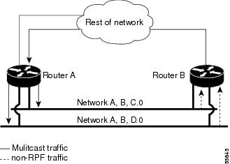
In a redundant configuration where multiple routers connect to the same LAN segment, only one router forwards the multicast traffic from the source to the receivers on the outgoing interfaces (see Figure 31-1). In this kind of topology, only the PIM designated router (PIM DR) forwards the data in the common VLAN, but the non-PIM DR receives the forwarded multicast traffic. The redundant router (non-PIM DR) must drop this traffic because it has arrived on the wrong interface and fails the RPF check. Traffic that fails the RPF check is called non-RPF traffic.
The Cisco 7600 series router processes non-RPF traffic in hardware on the PFC by filtering (dropping) or rate limiting the non-RPF traffic.
Figure 31-1 Redundant Multicast Router Configuration in a Stub Network
Filtering of RPF Failures for Stub Networks
The PFC and the DFCs support ACL-based filtering of RPF failures for sparse mode stub networks. When you enable the ACL-based method of filtering RPF failures by entering the mls ip multicast stub command on the redundant router, the following ACLs automatically download to the PFC and are applied to the interface you specify:
The ACLs filter RPF failures and drop them in hardware so that they are not forwarded to the router.
Use the ACL-based method of filtering RPF failures only in sparse mode stub networks where there are no downstream routers. For dense mode groups, RPF failure packets have to be seen on the router for the PIM assert mechanism to function properly. Use CEF-based or NetFlow-based rate limiting to limit the rate of RPF failures in dense mode networks and sparse mode transit networks.
For information on configuring ACL-based filtering of RPF failures, see the “Configuring ACL-Based Filtering of RPF Failures” section.
Rate Limiting of RPF Failure Traffic
When you enable rate limiting of packets that fail the RPF check (non-RPF packets), most non-RPF packets are dropped in hardware. According to the multicast protocol specification, the router needs to receive the non-RPF packets for the PIM assert mechanism to function properly, so all non-RPF packets cannot be dropped in hardware.
When a non-RPF packet is received, a NetFlow entry is created for each non-RPF flow.
When the first non-RPF packet arrives, the PFC bridges the packet to the MSFC and to any bridged ports and creates a NetFlow entry that contains source, group, and ingress interface information, after which the NetFlow entry handles all packets for that source and group, sending packets only to bridged ports and not to the MSFC.
To support the PIM assert mechanism, the PFC periodically forwards a percentage of the non-RPF flow packets to the MSFC.
The first packets for directly connected sources in PIM sparse mode are also rate-limited and are processed by the CPU.
Understanding How IPv4 Bidirectional PIM Works
The PFC3 supports hardware forwarding of IPv4 bidirectional PIM groups. To support IPv4 bidirectional PIM groups, the PFC3 implements a new mode called designated forwarder (DF) mode. The designated forwarder is the router elected to forward packets to and from a segment for a IPv4 bidirectional PIM group. In DF mode, the supervisor engine accepts packets from the RPF and from the DF interfaces.
When the supervisor engine is forwarding IPv4 bidirectional PIM groups, the RPF interface is always included in the outgoing interface list of (*,G) entry, and the DF interfaces are included depending on IGMP/PIM joins.
If the route to the RP becomes unavailable, the group is changed to dense mode. Should the RPF link to the RP become unavailable, the IPv4 bidirectional PIM flow is removed from the hardware FIB.
For information on configuring IPv4 bidirectional PIM, see the “Configuring IPv4 Bidirectional PIM” section.
Default IPv4 Multicast Layer 3 Switching Configuration
Table 31-1 shows the default IP multicast Layer 3 switching configuration.
|
|
|
|---|---|
Enabled when multicast routing is enabled and PIM is enabled on the interface |
Internet Group Management Protocol (IGMP) snooping is enabled by default on all VLAN interfaces. If you disable IGMP snooping on an interface, multicast Layer 3 flows are still switched by the hardware. Bridging of the flow on an interface with IGMP snooping disabled causes flooding to all forwarding interfaces of the VLAN. For details on configuring IGMP snooping, see Chapter33, “Configuring IGMP Snooping for IPv4 Multicast Traffic”
IPv4 Multicast Layer 3 Switching Configuration Guidelines and Restrictions
These sections describe IP Multicast Layer 3 switching configuration restrictions:
Restrictions
IP multicast Layer 3 switching is not provided for an IP multicast flow in the following situations:
- For IP multicast groups that fall into the range 224.0.0.* (where * is in the range 0 to 255), which is used by routing protocols. Layer 3 switching is supported for groups 225.0.0.* through 239.0.0.* and 224.128.0.* through 239.128.0.*.
Note![]() Groups in the 224.0.0.* range are reserved for routing control packets and must be flooded to all forwarding ports of the VLAN. These addresses map to the multicast MAC address range 01-00-5E-00-00-xx, where xx is in the range 0–0xFF.
Groups in the 224.0.0.* range are reserved for routing control packets and must be flooded to all forwarding ports of the VLAN. These addresses map to the multicast MAC address range 01-00-5E-00-00-xx, where xx is in the range 0–0xFF.
- For PIM auto-RP multicast groups (IP multicast group addresses 224.0.1.39 and 224.0.1.40).
- For packets with IP options. However, packets in the flow that do not specify IP options are hardware switched.
- For source traffic received on tunnel interfaces (such as MBONE traffic).
- If a (S,G) entry for sparse mode does not have the SPT-bit, RPT-bit, or Pruned flag set.
- A (*,G) entry is not hardware switched if at least one (S,G) entry has an RPF different from the (*,G) entry’s RPF and the (S,G) is not hardware switched.
- If the ingress interface of a (S,G) or (*,G) entry is null, except if the (*,G) entry is a IPv4 bidirectional PIM entry and the router is the RP for the group.
- For IPv4 bidirectional PIM entries when a DF interface or RPF interface is a tunnel.
- Supervisor Engine 32 does not support egress multicast replication and cannot detect the multicast replication mode.
- In a MFIB implementation, ip multicast rate-limit command that limits the number of data packets in either direction is not supported in hardware configurations.
- In a MFIB implementation, ip multicast ttl-threshold command is not supported in hardware configurations.
- In a MFIB implementation, Network Address Translation (NAT) is not supported in hardware configurations.
- Following MDSS commands are invalid after MFIB IPv4 implementation:
–![]() debug mdss [vrf <vrf-name>] [all | error | events | mdt | p2p | packet]
debug mdss [vrf <vrf-name>] [all | error | events | mdt | p2p | packet]
–![]() mls ip multicast [vrf <name>] connected {config command - global and interface-level}
mls ip multicast [vrf <name>] connected {config command - global and interface-level}
–![]() mls ip multicast consistency-check {config command - global and interface-level}
mls ip multicast consistency-check {config command - global and interface-level}
–![]() show mls ip multicast consistency-check
show mls ip multicast consistency-check
–![]() show mls ip multicast rp-mapping
show mls ip multicast rp-mapping
–![]() mls ip multicast non-rpf aging fast
mls ip multicast non-rpf aging fast
–![]() mls ip multicast non-rpf aging global
mls ip multicast non-rpf aging global
–![]() ip multicast replication-mode egress
ip multicast replication-mode egress
Unsupported Features
If you enable IP multicast Layer 3 switching, IP accounting for Layer 3 interfaces does not report accurate values. The show ip accounting command is not supported.
Multicast streaming is not supported across DMVPN on Cat6500 and 7600. Only multicast packets from the local control plane such as routing protocols are supported.
Configuring IPv4 Multicast Layer 3 Switching
These sections describe how to configure IP multicast Layer 3 switching:
- Source-Specific Multicast with IGMPv3, IGMP v3lite, and URD
- Enabling IPv4 Multicast Routing Globally
- Enabling IPv4 PIM on Layer 3 Interfaces
- Enabling IP Multicast Layer 3 Switching on Layer 3 Interfaces
- Configuring the Replication Mode
- Enabling Local Egress Replication
- Configuring the Layer 3 Switching Global Threshold
- Enabling Installation of Directly Connected Subnets
- Specifying the Flow Statistics Message Interval
- Configuring IPv4 Bidirectional PIM
- Setting the IPv4 Bidirectional PIM Scan Interval
- Configuring ACL-Based Filtering of RPF Failures
- Validating the Rate-Limiter Status
- Displaying IPv4 Multicast Layer 3 Hardware Switching Summary
- Displaying the IPv4 Multicast Routing Table
- Displaying IPv4 Multicast Layer 3 Switching Statistics
- Displaying IPv4 Bidirectional PIM Information
- Using IPv4 Debug Commands
Note![]() When you are in configuration mode you can enter EXEC mode commands by entering the do keyword before the EXEC mode command.
When you are in configuration mode you can enter EXEC mode commands by entering the do keyword before the EXEC mode command.
Source-Specific Multicast with IGMPv3, IGMP v3lite, and URD
For complete information and procedures about source-specific multicast with IGMPv3, IGMP v3lite, and URL Rendezvous Directory (URD), refer to this URL:
http://www.cisco.com/univercd/cc/td/doc/product/software/ios122/122cgcr/fipr_c/ipcpt3/1cfssm.htm
Enabling IPv4 Multicast Routing Globally
You must enable IP multicast routing globally before you can enable IP multicast Layer 3 switching on Layer 3 interfaces.
For complete information and procedures, refer to these publications:
http://www.cisco.com/en/US/docs/ios/12_2/iproute/command/reference/fiprrp_r.html
http://www.cisco.com/en/US/docs/ios/12_1/iproute/command/reference/ip_r.html
To enable IP multicast routing globally, perform this task:
|
|
|
|---|---|
This example shows how to enable multicast routing globally:
Enabling IPv4 PIM on Layer 3 Interfaces
You must enable PIM on the Layer 3 interfaces before IP multicast Layer 3 switching functions on those interfaces.
To enable IP PIM on a Layer 3 interface, perform this task:
|
|
|
|
|---|---|---|
Router(config)# interface {{ vlan vlan_ID } | { type 2 slot/port }} |
||
Router(config-if)# ip pim { dense-mode | sparse-mode | sparse-dense-mode } |
||
Router(config-if)# no ip pim [ dense-mode | sparse-mode | sparse-dense-mode ] |
|
2.type = ethernet, fastethernet, gigabitethernet, or tengigabitethernet |
This example shows how to enable PIM on an interface using the default mode (sparse-dense-mode):
This example shows how to enable PIM sparse mode on an interface:
Enabling IP Multicast Layer 3 Switching Globally
To enable hardware switching of multicast routes globally on your system, perform this task:
|
|
|
|
|---|---|---|
Displays brief information about the packet flows in the system. |
This example shows how to globally enable hardware switching of multicast routes:
Router(config)# show platform software multicast ip
(40.0.0.2, 232.0.1.4) Incoming interface: Lspvif0, Packets Switched: 119954142
Enabling IP Multicast Layer 3 Switching on Layer 3 Interfaces
IP multicast Layer 3 switching is enabled by default on the Layer 3 interface when you enable PIM on the interface. Perform this task only if you disabled IP multicast Layer 3 switching on the interface and you want to reenable it.
PIM can be enabled on any Layer 3 interface, including VLAN interfaces.
Note![]() You must enable PIM on all participating Layer 3 interfaces before IP multicast Layer 3 switching will function. For information on configuring PIM on Layer 3 interfaces, see the “Enabling IPv4 PIM on Layer 3 Interfaces” section.
You must enable PIM on all participating Layer 3 interfaces before IP multicast Layer 3 switching will function. For information on configuring PIM on Layer 3 interfaces, see the “Enabling IPv4 PIM on Layer 3 Interfaces” section.
To enable IP multicast Layer 3 switching on a Layer 3 interface, perform this task:
|
|
|
|
|---|---|---|
Router(config)# interface {{ vlan vlan_ID } | { type 3 slot/port }} |
||
Enables IP multicast Layer 3 switching on a Layer 3 interface. |
||
Disables IP multicast Layer 3 switching on a Layer 3 interface. |
|
3.type = ethernet, fastethernet, gigabitethernet, or tengigabitethernet |
This example shows how to enable IP multicast Layer 3 switching on a Layer 3 interface:
Configuring the Replication Mode
Note![]() Supervisor Engine 32 supports only ingress replication mode.
Supervisor Engine 32 supports only ingress replication mode.
The Supervisor Engine 720 supports the egress keyword. Support for the egress keyword is called “Multicast Enhancement - Replication Mode Detection” in the release notes and Feature Navigator.
By default, a Supervisor Engine 720 automatically detects the replication mode based on the module types installed in the system. If all modules are capable of egress replication, the system uses egress-replication mode. If the supervisor engine detects modules that are not capable of egress replication, the replication mode automatically changes to ingress replication. You can override this action by entering the ip multicast hardware-switching replication-mode egress command so that the system continues to work in egress-replication mode even if there are fabric-enabled modules installed that do not support egress replication (for example, OSMs). You can also configure the system to operate only in ingress-replication mode.
If the system is functioning in automatic detection mode, and you install a module that cannot perform egress replication, the following occurs:
- The system reverts to ingress mode
- A system log is generated
- A system reload occurs to revert to the old configuration
If the system is functioning in forced egress mode, a system log is created that will display the presence of modules that are not capable of egress replication mode.
Note![]() If you configure forced egress mode in a system that has fabric-enabled modules that are not capable of egress replication, you must make sure that these modules are not sourcing or receiving multicast traffic.
If you configure forced egress mode in a system that has fabric-enabled modules that are not capable of egress replication, you must make sure that these modules are not sourcing or receiving multicast traffic.
During a change from egress- to ingress-replication mode, traffic interruptions may occur because the shortcuts will be purged and reinstalled. To avoid interruptions in traffic forwarding, enter the ip multicast hardware-switching replication-mode ingress command in global configuration mode. This command forces the system to operate in ingress-replication mode.
The no form of the ip multicast hardware-switching replication-mode ingress command restores the system to auomatic detection mode.
To enable IP multicast Layer 3 switching, perform this task:
|
|
|
|
|---|---|---|
Router(config)# ip multicast hardware-switching replication-mode [ egress | ingress ] |
||
Displays the replication mode and if automatic detection is enabled or disabled. |
This example shows how to enable the replication mode:
Router (config)# ip multicast hardware-switching replication-mode egress
Router# show platform software multicast ip capability
Router# show platform software multicast ip summary
Router (config)#
Enabling Local Egress Replication
Note![]() Supervisor Engine 32 supports only ingress replication mode.
Supervisor Engine 32 supports only ingress replication mode.
With a Supervisor Engine 720, you can unconditionally enable local egress replication. This feature is called “Multicast enhancement - egress replication performance improvement” in the release notes and Feature Navigator.
DFC-equipped modules with dual switch-fabric connections host two packet replication engines, one per fabric connection. Each replication engine is responsible for forwarding packets to and from the interfaces associated with the switch-fabric connections. The interfaces that are associated with a switch-fabric connection are considered to be “local” from the perspective of the packet replication engine.
You can prevent redundant replication of multicast packets across the switch-fabric connection by entering a command that instructs the two replication engines on these modules to forward packets only to local interfaces which are associated with the switch-fabric connection that the replication engine supports.
When you enable this feature, the multicast expansion table (MET) for each replication engine is populated with the local Layer 3 interfaces only. This action prevents replication for interfaces that are not supported by the replication engine (nonlocal interfaces) and increases replication performance.
Local egress replication is supported with the following software configuration and hardware:
- IPv4 egress replication mode
- Dual fabric-connection DFC-equipped modules
- Layer 3-routed interfaces and subinterfaces that are not part of a port channel
The local egress replication feature is not supported for the following internal VLANs:
- Egress internal VLAN
- Partial-shortcut internal VLAN
- Internal VLAN for Multicast VPN Multicast Distribution Tree (MDT) tunnel
- Point-to-point tunnel internal VLAN
- QoS internal VLAN
Note![]() The local egress replication feature is not supported with IPv6 multicast or in a system that has a mix of IPv4 and IPv6 multicast enabled.
The local egress replication feature is not supported with IPv6 multicast or in a system that has a mix of IPv4 and IPv6 multicast enabled.
To enable local egress replication, perform this task:
|
|
|
|
|---|---|---|
Enables local egress replication. Note This command requires a system reset for the configuration to take effect. |
||
This example shows how to enable local egress replication:
Configuring the Layer 3 Switching Global Threshold
You can configure a global multicast rate threshold (specified in packets per second) below which all multicast traffic is routed by the MSFC. This configuration prevents creation of switching cache entries for low-rate Layer 3 flows.
Note![]() This command does not affect flows that are already being routed. To apply the threshold to existing routes, clear the route and let it reestablish.
This command does not affect flows that are already being routed. To apply the threshold to existing routes, clear the route and let it reestablish.
To configure the Layer 3 switching threshold, perform this task:
|
|
|
|---|---|
This example shows how to configure the Layer 3 switching threshold to 10 packets per second:
Enabling Installation of Directly Connected Subnets
In PIM sparse mode, a first-hop router that is the designated router for the interface may need to encapsulate the source traffic in a PIM register message and unicast it to the rendezvous point. To prevent new sources for the group from being learned in the routing table, the (*,G) flows should remain as completely hardware-switched flows. When (subnet/mask, 224/4) entries are installed in the hardware, the FIB allows both (*,G) flows to remain completely hardware-switched flows, and new, directly connected sources to be learned correctly. The installation of directly connected subnets is enabled globally by default. One (subnet/mask, 224/4) is installed per PIM-enabled interface.
To view FIB entries, enter the show platform software multicast ip connected command.
To enable installation of directly connected subnets, perform this task:
|
|
|
|---|---|
This example shows how to enable installation of directly connected subnets:
Specifying the Flow Statistics Message Interval
By default, the supervisor engine forwards flow statistics messages to the MSFC every 25 seconds. The messages are forwarded in batches, and each batch of messages contains statistics for 25 percent of all flows. If you leave the interval at the default of 25 seconds, it will take 100 seconds to forward statistics for all flows to the MSFC.
To specify how often flow statistics messages forwarded from the supervisor engine to the MSFC, perform this task:
|
|
|
|---|---|
Specifies how the supervisor engine forwards flow statistics messages to the MSFC. |
|
This example shows how to configure the supervisor engine to forward flow statistics messages to the MSFC every 10 seconds:
Configuring ACL-Based Filtering of RPF Failures
When you configure ACL-based filtering of RPF failures, ACLs that filter RPF failures in hardware are downloaded to the hardware-based ACL engine and applied on the interface you specify.
To enable ACL-based filtering of RPF failures on an interface, perform this task:
|
|
|
|
|---|---|---|
Router(config)# interface {{ vlan vlan_ID } | { type 4 slot/port } | { port-channel number }} |
||
Enables ACL-based filtering of RPF failures on an interface. |
||
Disables ACL-based filtering of RPF failures on an interface. |
|
4.type = ethernet, fastethernet, gigabitethernet, or tengigabitethernet |
Validating the Rate-Limiter Status
To validate the rater-limiter status, perform this task:
|
|
|
|---|---|
Displays RPF failure rate-limiting information with the current state of the rate limiter. |
This example shows how to display RPF failure rate-limiting information:
Displaying IPv4 Multicast Layer 3 Hardware Switching Summary
Note![]() The show interface statistics command does not display hardware-switched packets, only packets switched by software.
The show interface statistics command does not display hardware-switched packets, only packets switched by software.
The show ip pim interface count command displays the IP multicast Layer 3 switching enable state on IP PIM interfaces and the number of packets received and sent on the interface.
To display IP multicast Layer 3 switching information for an IP PIM Layer 3 interface, perform one of these tasks:
|
|
|
|---|---|
Router# show ip pim interface [{{ vlan vlan_ID } | { type 5 slot/port } | { port-channel number }}] count |
Displays IP multicast Layer 3 switching enable state information for all MSFC IP PIM Layer 3 interfaces. |
Displays the IP multicast Layer 3 switching enable state on the Layer 3 interfaces. |
|
5.type = ethernet, fastethernet, gigabitethernet, or tengigabitethernet |
These examples show how to display the IP PIM configuration of the interfaces:
The “*” flag indicates that this interface can be fast switched and the “H” flag indicates that this interface is hardware switched. The “In” flag indicates the number of multicast packet bytes that have been received on the interface. The “Out” flag indicates the number of multicast packet bytes that have been forwarded from this interface.
Note![]() The -tive counter means that the outgoing interface list of the corresponding entry is NULL, and this indicates that this flow is still active.
The -tive counter means that the outgoing interface list of the corresponding entry is NULL, and this indicates that this flow is still active.
This example shows how to display the IP multicast Layer 3 switching configuration of interface VLAN 10:
This example shows how to display the IP multicast Layer 3 switching configuration of Gigabit Ethernet interface 1/2:
Displaying the IPv4 Multicast Routing Table
The show ip mroute command displays the IP multicast routing table.
To display the IP multicast routing table, perform this task:
|
|
|
|---|---|
Router# show ip mroute partical-sc [ hostname | group_number ] |
Displays the IP multicast routing table and the hardware-switched interfaces. |
This example shows how to display the IP multicast routing table:
Note![]() The RPF-MFD flag indicatesthat the flow is completely switched by the hardware. The H flag indicates the flow is switched by the hardware on the outgoing interface.
The RPF-MFD flag indicatesthat the flow is completely switched by the hardware. The H flag indicates the flow is switched by the hardware on the outgoing interface.
Displaying IPv4 Multicast Layer 3 Switching Statistics
The show platform software multicast ip command displays detailed information about IP multicast Layer 3 switching.
To display detailed IP multicast Layer 3 switching information, perform one of these tasks:
This example shows how to display information on a specific IP multicast Layer 3 switching entry:
This example shows how to display IP multicast group information:
This example shows how to display IP multicast Layer 3 switching information for gigabitethernet interface 3/2/1:
This example shows how to display the IP multicast Layer 3 switching statistics:
Configuring IPv4 Bidirectional PIM
These sections describe how to configure IPv4 bidirectional protocol independent multicast (PIM):
- Enabling IPv4 Bidirectional PIM Globally
- Configuring the Rendezvous Point for IPv4 Bidirectional PIM Groups
- Setting the IPv4 Bidirectional PIM Scan Interval
- Displaying IPv4 Bidirectional PIM Information
Enabling IPv4 Bidirectional PIM Globally
To enable IPv4 bidirectional PIM, perform this task:
|
|
|
|---|---|
This example shows how to enable IPv4 bidirectional PIM on the router:
Configuring the Rendezvous Point for IPv4 Bidirectional PIM Groups
To statically configure the rendezvous point for an IPv4 bidirectional PIM group, perform this task:
This example shows how to configure a static rendezvous point for an IPv4 bidirectional PIM group:
Setting the IPv4 Bidirectional PIM Scan Interval
You can specify the interval between the IPv4 bidirectional PIM RP Reverse Path Forwarding (RPF) scans.
To set the IPv4 bidirectional PIM RP RPF scan interval, perform this task:
This example shows how to set the IPv4 bidirectional PIM RP RPF scan interval:
Router(config)# mls ip multicast bidir gm-scan-interval 30
Router(config)#
Displaying IPv4 Bidirectional PIM Information
To display IPv4 bidirectional PIM information, perform one of these tasks:
|
|
|
|---|---|
Displays mappings between PIM groups and rendezvous points and shows learned rendezvous points in use. |
|
This example shows how to display information about the PIM group and rendezvous point mappings:
This example shows how to display information in the IP multicast routing table that is related to IPv4 bidirectional PIM:
This example show how to display information related to a specific multicast route. In the output below, the arrow in the margin points to information about a partical short cut:
This example shows how to display the entries for a specific multicast group address:
Using IPv4 Debug Commands
Table 31-2 describes IPv4 multicast Layer 3 switching debug commands that you can use to troubleshoot IP multicast Layer 3 switching problems.
Note![]() The old debug commands will not be available.
The old debug commands will not be available.
 Feedback