- Preface
- Product Overview
- Configuring the Router for the First Time
- Configuring a Supervisor Engine 720
- Configuring a Route Switch Processor 720
- Configuring NSF with SSO Supervisor Engine Redundancy
- ISSU and eFSU on Cisco 7600 Series Routers
- Configuring RPR and RPR+ Supervisor Engine Redundancy
- Configuring Interfaces
- Configuring a Supervisor Engine 32
- Configuring LAN Ports for Layer 2 Switching
- Configuring Flex Links
- Configuring EtherChannels
- Configuring VTP
- Configuring VLANs
- Configuring Private VLANs
- Configuring Cisco IP Phone Support
- Configuring IEEE 802.1Q Tunneling
- Configuring Layer 2 Protocol Tunneling
- Configuring L2TPv3
- Configuring STP and MST
- Configuring Optional STP Features
- Configuring Layer 3 Interfaces
- Configuring GTP-SLB IPV6 Support
- IP Subscriber Awareness over Ethernet
- Configuring UDE and UDLR
- Configuring Multiprotocol Label Switching on the PFC
- Configuring IPv4 Multicast VPN Support
- Configuring Multicast VPN Extranet Support
- Configuring IP Unicast Layer 3 Switching
- Configuring IPv6 Multicast PFC3 and DFC3 Layer 3 Switching
- Configuring IPv4 Multicast Layer 3 Switching
- Configuring MLDv2 Snooping for IPv6 Multicast Traffic
- Configuring IGMP Snooping for IPv4 Multicast Traffic
- Configuring PIM Snooping
- Configuring Network Security
- Understanding Cisco IOS ACL Support
- Configuring VRF aware 6RD Tunnels
- Configuring VLAN ACLs
- Private Hosts (Using PACLs)
- Configuring IPv6 PACL
- IPv6 First-Hop Security Features
- Configuring Online Diagnostics
- Configuring Denial of Service Protection
- Configuring DHCP Snooping
- Configuring Dynamic ARP Inspection
- Configuring Traffic Storm Control
- Unknown Unicast Flood Blocking
- Configuring PFC QoS
- Configuring PFC QoS Statistics Data Export
- Configuring MPLS QoS on the PFC
- Configuring LSM MLDP based MVPN Support
- Configuring IEEE 802.1X Port-Based Authentication
- Configuring IEEE 802.1ad
- Configuring Port Security
- Configuring UDLD
- Configuring NetFlow and NDE
- Configuring Local SPAN, RSPAN, and ERSPAN
- Configuring SNMP IfIndex Persistence
- Power Management and Environmental Monitoring
- Configuring Web Cache Services Using WCCP
- Using the Top N Utility
- Using the Layer 2 Traceroute Utility
- Configuring Bidirectional Forwarding and Detection over Switched Virtual Interface
- Configuring Call Home
- Configuring IPv6 Policy Based Routing
- Using the Mini Protocol Analyzer
- Configuring Resilient Ethernet Protocol
- Configuring Synchronous Ethernet
- Configuring Link State Tracking
- Configuring BGP PIC Edge and Core for IP and MPLS
- Configuring VRF aware IPv6 tunnels over IPv4 transport
- ISIS IPv4 Loop Free Alternate Fast Reroute (LFA FRR)
- Multicast Service Reflection
- Y.1731 Performance Monitoring
- Online Diagnostic Tests
- Acronyms
- Cisco IOS Release 15S Software Images
- Index
- Understanding IEEE 802.1X Port-Based Authentication
- Default IEEE 802.1X Port-Based Authentication Configuration
- IEEE 802.1X Port-Based Authentication Guidelines and Restrictions
- Configuring IEEE 802.1X Port-Based Authentication
- Enabling IEEE 802.1X Port-Based Authentication
- ConfiguringRouter-to-RADIUS-Server Communication
- Enabling Periodic Reauthentication
- Manually Reauthenticating the Client Connected to a Port
- Initializing Authentication for the Client Connected to a Port
- Changing the Quiet Period
- Changing the Router-to-Client Retransmission Time
- Setting the Router-to-Client Retransmission Time for EAP-Request Frames
- Setting the Router-to-Authentication-Server Retransmission Time for Layer4 Packets
- Setting the Router-to-Client Frame Retransmission Number
- Enabling Multiple Hosts
- Resetting the IEEE 802.1X Configuration to the Default Values
- Displaying IEEE 802.1X Status
Configuring IEEE 802.1X Port-Based Authentication
This chapter describes how to configure IEEE 802.1X port-based authentication to prevent unauthorized devices (clients) from gaining access to the network.

Note For complete syntax and usage information for the commands used in this chapter, refer to the Cisco 7600 Series Routers Command References at this URL:
http://www.cisco.com/en/US/products/hw/routers/ps368/prod_command_reference_list.html
Understanding IEEE 802.1X Port-Based Authentication
The IEEE 802.1X standard defines a client-server-based access control and authentication protocol that restricts unauthorized clients from connecting to a LAN through publicly accessible ports. The authentication server authenticates each client connected to a router port and assigns the port to a VLAN before making available any services offered by the router or the LAN.
Until the client is authenticated, 802.1X access control allows only Extensible Authentication Protocol over LAN (EAPOL) traffic through the port to which the client is connected. After authentication is successful, normal traffic can pass through the port.
These sections describe 802.1X port-based authentication:
- Device Roles
- Authentication Initiation and Message Exchange
- Ports in Authorized and Unauthorized States
- Using IEEE 802.1X Authentication with DHCP Snooping
- Supported Topologies
Device Roles
With IEEE 802.1X port-based authentication, the devices in the network have specific roles as shown in Figure 52-1.
Figure 52-1 802.1X Device Roles
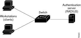
The specific roles shown in Figure 52-1 are as follows:
- Client —The device (workstation) that requests access to the LAN and router services and responds to requests from the router. The workstation must be running 802.1X-compliant client software such as that offered in the Microsoft Windows XP operating system. (The client is the supplicant in the 802.1X specification.)
Note![]() To resolve Windows XP network connectivity and 802.1X port-based authentication issues, read the Microsoft Knowledge Base article at this URL: http://support.microsoft.com/kb/q303597/
To resolve Windows XP network connectivity and 802.1X port-based authentication issues, read the Microsoft Knowledge Base article at this URL: http://support.microsoft.com/kb/q303597/
- Authentication server —Performs the actual authentication of the client. The authentication server validates the identity of the client and notifies the router whether or not the client is authorized to access the LAN and router services. Because the router acts as the proxy, the authentication service is transparent to the client. The Remote Authentication Dial-In User Service (RADIUS) security system with Extensible Authentication Protocol (EAP) extensions is the only supported authentication server; it is available in Cisco Secure Access Control Server, version 3.0. RADIUS uses a client-server model in which secure authentication information is exchanged between the RADIUS server and one or more RADIUS clients.
- Router (also called the authenticator and back-end authenticator)—Controls the physical access to the network based on the authentication status of the client. The router acts as an intermediary (proxy) between the client and the authentication server, requesting identity information from the client, verifying that information with the authentication server, and relaying a response to the client. The router includes the RADIUS client, which is responsible for encapsulating and decapsulating the EAP frames and interacting with the authentication server.
When the router receives EAPOL frames and relays them to the authentication server, the Ethernet header is stripped and the remaining EAP frame is re-encapsulated in the RADIUS format. The EAP frames are not modified or examined during encapsulation, and the authentication server must support EAP within the native frame format. When the router receives frames from the authentication server, the server’s frame header is removed, leaving the EAP frame, which is then encapsulated for Ethernet and sent to the client.
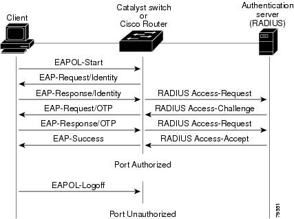
Authentication Initiation and Message Exchange
The router or the client can initiate authentication. If you enable authentication on a port by using the dot1x port-control auto interface configuration command, the router must initiate authentication when it determines that the port link state transitions from down to up. The router then sends an EAP-request/identity frame to the client to request its identity (typically, the router sends an initial identity request frame followed by one or more requests for authentication information). When the client receives the frame, it responds with an EAP-response/identity frame.
If the client does not receive an EAP-request/identity frame from the router during bootup, the client can initiate authentication by sending an EAPOL-start frame, which prompts the router to request the client’s identity.
Note![]() If IEEE 802.1X is not enabled or supported on the network access device, any EAPOL frames from the client are dropped. If the client does not receive an EAP-request/identity frame after three attempts to start authentication, the client transmits frames as if the port is in the authorized state. A port in the authorized state effectively means that the client has been successfully authenticated. For more information, see the “Ports in Authorized and Unauthorized States” section.
If IEEE 802.1X is not enabled or supported on the network access device, any EAPOL frames from the client are dropped. If the client does not receive an EAP-request/identity frame after three attempts to start authentication, the client transmits frames as if the port is in the authorized state. A port in the authorized state effectively means that the client has been successfully authenticated. For more information, see the “Ports in Authorized and Unauthorized States” section.
When the client supplies its identity, the router begins its role as the intermediary, passing EAP frames between the client and the authentication server until authentication succeeds or fails. If the authentication succeeds, the router port becomes authorized. For more information, see the “Ports in Authorized and Unauthorized States” section.
The specific exchange of EAP frames depends on the authentication method being used. Figure 52-2 shows a message exchange initiated by the client using the One-Time-Password (OTP) authentication method with a RADIUS server.
Ports in Authorized and Unauthorized States
The router port state determines whether or not the client is granted access to the network. The port starts in the unauthorized state. While in this state, the port disallows all ingress and egress traffic except for IEEE 802.1X protocol packets. When a client is successfully authenticated, the port transitions to the authorized state, allowing all traffic for the client to flow normally.
If a client that does not support 802.1X is connected to an unauthorized 802.1X port, the router requests the client’s identity. In this situation, the client does not respond to the request, the port remains in the unauthorized state, and the client is not granted access to the network.
In contrast, when an 802.1X-enabled client connects to a port that is not running the 802.1X protocol, the client initiates the authentication process by sending the EAPOL-start frame. When no response is received, the client sends the request for a fixed number of times. Because no response is received, the client begins sending frames as if the port is in the authorized state.
You control the port authorization state by using the dot1x port-control interface configuration command and these keywords:
- force-authorized —Disables 802.1X port-based authentication and causes the port to transition to the authorized state without any authentication exchange required. The port transmits and receives normal traffic without 802.1X-based authentication of the client. This is the default setting.
- force-unauthorized —Causes the port to remain in the unauthorized state, ignoring all attempts by the client to authenticate. The router cannot provide authentication services to the client through the interface.
- auto —Enables 802.1X port-based authentication and causes the port to begin in the unauthorized state, allowing only EAPOL frames to be sent and received through the port. The authentication process begins when the link state of the port transitions from down to up or when an EAPOL-start frame is received. The router requests the identity of the client and begins relaying authentication messages between the client and the authentication server. Each client attempting to access the network is uniquely identified by the router by using the client’s MAC address.
If the client is successfully authenticated (receives an Accept frame from the authentication server), the port state changes to authorized, and all frames from the authenticated client are allowed through the port. If the authentication fails, the port remains in the unauthorized state, but authentication can be retried. If the authentication server cannot be reached, the router can retransmit the request. If no response is received from the server after the specified number of attempts, authentication fails, and network access is not granted.
When a client logs off, it sends an EAPOL-logoff message, causing the router port to transition to the unauthorized state.
If the link state of a port transitions from up to down, or if an EAPOL-logoff frame is received, the port returns to the unauthorized state.
Using IEEE 802.1X Authentication with DHCP Snooping
When the Dynamic Host Configuration Protocol (DHCP) snooping option-82 with data insertion feature is enabled, the router can insert a client’s IEEE 802.1X-authenticated user identity information into the DHCP discovery process, allowing the DHCP server to assign IP addresses from different IP address pools to different classes of end users. This feature allows you to secure the IP addresses given to the end users for accounting purposes and to grant services based on Layer 3 criteria.
After a successful 802.1X authentication, the port is put into the forwarding state and stores the attributes that it receives from the RADIUS server. While performing DHCP snooping, the router acts as a DHCP relay agent, receiving DHCP messages and regenerating those messages for transmission on another interface.
After 802.1X authentication, when a client sends a DHCP discovery message, the router receives the packet and adds a RADIUS attributes suboption section to the packet containing the stored RADIUS attributes of the client. The router then submits the discovery broadcast again. The DHCP server receives the modified DHCP discovery packet and can, if configured to do so, use the authenticated user identity information when creating the IP address assignment.
The mapping of user to IP address can be on a one-to-one, one-to-many, or many-to-many basis. The one-to-many mapping allows the same user to authenticate through 802.1X hosts on multiple ports.
When 801.X authentication and DHCP snooping option-82 with data insertion features are enabled, the router will automatically insert the authenticated user identity information. To configure DHCP snooping option-82 with data insertion see the “DHCP Snooping Option-82 Data Insertion” section on page 37-3.
For information about the data inserted in the RADIUS attributes suboption, see RFC 4014, “Remote Authentication Dial-In User Service (RADIUS) Attributes Suboption for the Dynamic Host Configuration Protocol (DHCP) Relay Agent Information Option.”
Supported Topologies
The IEEE 802.1X port-based authentication is supported in two topologies:
In a point-to-point configuration (see Figure 52-1), only one client can be connected to the 802.1X-enabled router port. The router detects the client when the port link state changes to the up state. If a client leaves or is replaced with another client, the router changes the port link state to down, and the port returns to the unauthorized state.
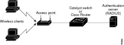
Figure 52-3 shows 802.1X port-based authentication in a wireless LAN. The 802.1X port is configured as a multiple-host port that becomes authorized as soon as one client is authenticated. When the port is authorized, all other hosts indirectly attached to the port are granted access to the network. If the port becomes unauthorized (reauthentication fails or an EAPOL-logoff message is received), the router denies access to the network to all of the attached clients. In this topology, the wireless access point is responsible for authenticating the clients attached to it, and the wireless access point acts as a client to the router.
Figure 52-3 Wireless LAN Example
Default IEEE 802.1X Port-Based Authentication Configuration
Table 52-1 shows the default IEEE 802.1X configuration.
IEEE 802.1X Port-Based Authentication Guidelines and Restrictions
When configuring IEEE 802.1X port-based authentication, follow these guidelines and restrictions:
- When 802.1X is enabled, ports are authenticated before any other Layer 2 or Layer 3 features are enabled.
- The 802.1X protocol is supported on both Layer 2 static-access ports and Layer 3 routed ports, but it is not supported on these port types:
–![]() Trunk port—If you try to enable 802.1X on a trunk port, an error message appears, and 802.1X is not enabled. If you try to change the mode of an 802.1X-enabled port to trunk, the port mode is not changed.
Trunk port—If you try to enable 802.1X on a trunk port, an error message appears, and 802.1X is not enabled. If you try to change the mode of an 802.1X-enabled port to trunk, the port mode is not changed.
–![]() EtherChannel port—Before enabling 802.1X on the port, you must first remove it from the EtherChannel port-channel interface. If you try to enable 802.1X on an EtherChannel port-channel interface or on an individual active port in an EtherChannel, an error message appears, and 802.1X is not enabled. If you enable 802.1X on a not-yet-active individual port of an EtherChannel, the port does not join the EtherChannel.
EtherChannel port—Before enabling 802.1X on the port, you must first remove it from the EtherChannel port-channel interface. If you try to enable 802.1X on an EtherChannel port-channel interface or on an individual active port in an EtherChannel, an error message appears, and 802.1X is not enabled. If you enable 802.1X on a not-yet-active individual port of an EtherChannel, the port does not join the EtherChannel.
–![]() Secure port—You cannot configure a secure port as an 802.1X port. If you try to enable 802.1X on a secure port, an error message appears, and 802.1X is not enabled. If you try to change an 802.1X-enabled port to a secure port, an error message appears, and the security settings are not changed.
Secure port—You cannot configure a secure port as an 802.1X port. If you try to enable 802.1X on a secure port, an error message appears, and 802.1X is not enabled. If you try to change an 802.1X-enabled port to a secure port, an error message appears, and the security settings are not changed.
–![]() Switch Port Analyzer (SPAN) destination port—You can enable 802.1X on a port that is a SPAN destination port; however, 802.1X is disabled until the port is removed as a SPAN destination port. You can enable 802.1X on a SPAN source port.
Switch Port Analyzer (SPAN) destination port—You can enable 802.1X on a port that is a SPAN destination port; however, 802.1X is disabled until the port is removed as a SPAN destination port. You can enable 802.1X on a SPAN source port.
Configuring IEEE 802.1X Port-Based Authentication
These sections describe how to configure IEEE 802.1X port-based authentication:
- Enabling IEEE 802.1X Port-Based Authentication
- Configuring Router-to-RADIUS-Server Communication
- Enabling Periodic Reauthentication
- Manually Reauthenticating the Client Connected to a Port
- Initializing Authentication for the Client Connected to a Port
- Changing the Quiet Period
- Setting the Router-to-Client Retransmission Time for EAP-Request Frames
- Setting the Router-to-Authentication-Server Retransmission Time for Layer 4 Packets
- Setting the Router-to-Client Frame Retransmission Number
- Enabling Multiple Hosts
- Resetting the IEEE 802.1X Configuration to the Default Values
Enabling IEEE 802.1X Port-Based Authentication
To enable IEEE 802.1X port-based authentication, you must enable AAA and specify the authentication method list. A method list describes the sequence and authentication methods to be queried to authenticate a user.
The software uses the first method listed to authenticate users; if that method fails to respond, the software selects the next authentication method in the method list. This process continues until there is successful communication with a listed authentication method or until all defined methods are exhausted. If authentication fails at any point in this cycle, the authentication process stops, and no other authentication methods are attempted.
To configure 802.1X port-based authentication, perform this task in global configuration mode:
When you enable 802.1X port-based authentication, note the following information:
- To create a default list that is used when a named list is not specified in the authentication command, use the default keyword followed by the methods that are to be used in default situations. The default method list is automatically applied to all interfaces.
- Enter at least one of these keywords:
–![]() group radius —Use the list of all RADIUS servers for authentication.
group radius —Use the list of all RADIUS servers for authentication.
–![]() none —Use no authentication. The client is automatically authenticated by the router without using the information supplied by the client.
none —Use no authentication. The client is automatically authenticated by the router without using the information supplied by the client.
This example shows how to enable AAA and 802.1X on Fast Ethernet port 5/1:
This example shows how to verify the configuration:
Configuring Router-to-RADIUS-Server Communication
RADIUS security servers are identified by any of the following:
- Host name
- Host IP address
- Host name and specific UDP port numbers
- IP address and specific UDP port numbers
The combination of the IP address and UDP port number creates a unique identifier, which enables RADIUS requests to be sent to multiple UDP ports on a server at the same IP address. If two different host entries on the same RADIUS server are configured for the same service (for example, authentication) the second host entry configured acts as the failover backup to the first one. The RADIUS host entries are tried in the order that they were configured.
To configure the RADIUS server parameters, perform this task in global configuration mode:
When you configure the RADIUS server parameters, note the following information:
- For hostname or ip_address, s pecify the host name or IP address of the remote RADIUS server.
- Specify the key string on a separate command line.
- For key string , specify the authentication and encryption key used between the router and the RADIUS daemon running on the RADIUS server. The key is a text string that must match the encryption key used on the RADIUS server.
- When you specify the key string, spaces within and at the end of the key are used. If you use spaces in the key, do not enclose the key in quotation marks unless the quotation marks are part of the key. This key must match the encryption used on the RADIUS daemon.
- You can globally configure the timeout, retransmission, and encryption key values for all RADIUS servers by using the radius-server host global configuration command. If you want to configure these options on a per-server basis, use the radius-server timeout, radius-server retransmit, and the radius-server key global configuration commands. For more information, refer to the Cisco IOS Security Configuration Guide, Release 12.2 and the Cisco IOS Security Command Reference, Release 12.2 at these URLs:
http://www.cisco.com/en/US/products/sw/iosswrel/ps1835/products_installation_and_configuration_guides_list.html
http://www.cisco.com/en/US/products/sw/iosswrel/ps1835/prod_command_reference_list.html
Note![]() You also need to configure some settings on the RADIUS server. These settings include the IP address of the router and the key string to be shared by both the server and the router. For more information, refer to the RADIUS server documentation.
You also need to configure some settings on the RADIUS server. These settings include the IP address of the router and the key string to be shared by both the server and the router. For more information, refer to the RADIUS server documentation.
This example shows how to configure the RADIUS server parameters on the router:
Enabling Periodic Reauthentication
You can enable periodic IEEE 802.1X client reauthentication and specify how often it occurs. If you do not specify a time period before enabling reauthentication, the number of seconds between reauthentication attempts is 3600.
Automatic 802.1X client reauthentication is a global setting and cannot be set for clients connected to individual ports. To manually reauthenticate the client connected to a specific port, see the “Manually Reauthenticating the Client Connected to a Port” section.
To enable periodic reauthentication of the client and to configure the number of seconds between reauthentication attempts, perform this task in interface configuration mode:
This example shows how to enable periodic reauthentication, set the number of seconds between reauthentication attempts to 4000, then verify the entries:
Manually Reauthenticating the Client Connected to a Port
Note![]() Reauthentication does not disturb the status of an already authorized port.
Reauthentication does not disturb the status of an already authorized port.
To manually reauthenticate the client connected to a port, perform this task:
|
|
|
|
|---|---|---|
Manually reauthenticates the client connected to a port. type — ethernet, fastethernet, gigabitethernet, or tengigabitethernet. |
||
This example shows how to manually reauthenticate the client connected to Fast Ethernet port 5/1 then verify the entries:
Initializing Authentication for the Client Connected to a Port
Note![]() Initializing authentication disables any existing authentication before authenticating the client connected to the port.
Initializing authentication disables any existing authentication before authenticating the client connected to the port.
To initialize the authentication for the client connected to a port, perform this task in privileged EXEC mode:
|
|
|
|
|---|---|---|
Initializes the authentication for the client connected to a port. type — ethernet, fastethernet, gigabitethernet, or tengigabitethernet. |
||
This example shows how to initialize the authentication for the client connected to Fast Ethernet port 5/1 then verify the entries:
Changing the Quiet Period
When the router cannot authenticate the client, the router remains idle for a set period of time, and then tries again. The idle time is determined by the quiet-period value. A failed authentication of the client might occur because the client provided an invalid password. You can provide a faster response time to the user by entering a smaller number than the default.
To change the quiet period, perform this task in interface configuration mode:
This example shows how to set the quiet time on the router to 30 seconds then verify the entries:
Changing the Router-to-Client Retransmission Time
The client responds to the EAP-request/identity frame from the router with an EAP-response/identity frame. If the router does not receive this response, it waits a set period of time (known as the retransmission time), and then retransmits the frame.
Note![]() You should change the default value of this command only to adjust for unusual circumstances such as unreliable links or specific behavioral problems with certain clients and authentication servers.
You should change the default value of this command only to adjust for unusual circumstances such as unreliable links or specific behavioral problems with certain clients and authentication servers.
To change the amount of time that the router waits for client notification, perform this task in interface configuration mode:
This example shows how to set 60 as the number of seconds that the router waits for a response to an EAP-request/identity frame from the client before retransmitting the request, then verify the entries:
Setting the Router-to-Client Retransmission Time for EAP-Request Frames
The client notifies the router that it received the EAP-request frame. If the router does not receive this notification, the router waits a set period of time, and then retransmits the frame. You may set the amount of time that the router waits for notification from 1 to 65535 seconds. (The default is 30 seconds.)
To set the router-to-client retransmission time for the EAP-request frames, perform this task in interface configuration mode:
|
|
|
|
|---|---|---|
Selects an interface to configure. type — ethernet, fastethernet, gigabitethernet, or tengigabitethernet. |
||
| Sets the router-to-client retransmission time for the EAP-request frame. |
||
This example shows how to set the router-to-client retransmission time for the EAP-request frame to 25 seconds, then verify the entries:
Setting the Router-to-Authentication-Server Retransmission Time for Layer 4 Packets
The authentication server notifies the router each time it receives a Layer 4 packet. If the router does not receive a notification after sending a packet, the router waits a set period of time and then retransmits the packet. You may set the amount of time that the router waits for notification from 1 to 65535 seconds. (The default is 30 seconds.)
To set the value for the retransmission of Layer 4 packets from the router to the authentication server, perform this task in interface configuration mode:
This example shows how to set the router-to-authentication-server retransmission time for Layer 4 packets to 25 seconds, then verify the entries:
Setting the Router-to-Client Frame Retransmission Number
In addition to changing the router-to-client retransmission time, you can change the number of times that the router sends an EAP-request/identity frame (assuming no response is received) to the client before restarting the authentication process.
Note![]() You should change the default value of this command only to adjust for unusual circumstances such as unreliable links or specific behavioral problems with certain clients and authentication servers.
You should change the default value of this command only to adjust for unusual circumstances such as unreliable links or specific behavioral problems with certain clients and authentication servers.
To set the router-to-client frame retransmission number, perform this task in interface configuration mode:
This example shows how to set 5 as the number of times that the router sends an EAP-request/identity request before restarting the authentication process, then verify the entries:
Enabling Multiple Hosts
You can attach multiple hosts to a single IEEE 802.1X-enabled port as shown in Figure 52-3. In this mode, only one of the attached hosts must be successfully authorized for all hosts to be granted network access. If the port becomes unauthorized (reauthentication fails or an EAPOL-logoff message is received), all attached clients are denied access to the network.
To allow multiple hosts (clients) on an 802.1X-authorized port that has the dot1x port-control interface configuration command set to auto, perform this task in interface configuration mode:
This example shows how to enable 802.1X on Fast Ethernet interface 5/1, allow multiple hosts, then verify the entries:
Resetting the IEEE 802.1X Configuration to the Default Values
To reset the IEEE 802.1X configuration to the default values, perform this task in interface configuration mode:
|
|
|
|
|---|---|---|
Selects an interface to configure. type — ethernet, fastethernet, gigabitethernet, or tengigabitethernet. |
||
Resets the configurable 802.1X parameters to the default values. |
||
Displaying IEEE 802.1X Status
To display global IEEE 802.1X administrative and operational status for the router, use the show dot1x privileged EXEC command. To display the 802.1X administrative and operational status for a specific interface, use the show dot1x interface interface-id privileged EXEC command.
For detailed information about the keywords and arguments in these commands, refer to the Cisco IOS Security Command Reference, Release 12.2 SR.
 Feedback