- Preface
- Product Overview
- Configuring the Router for the First Time
- Configuring a Supervisor Engine 720
- Configuring a Route Switch Processor 720
- Configuring NSF with SSO Supervisor Engine Redundancy
- ISSU and eFSU on Cisco 7600 Series Routers
- Configuring RPR and RPR+ Supervisor Engine Redundancy
- Configuring Interfaces
- Configuring a Supervisor Engine 32
- Configuring LAN Ports for Layer 2 Switching
- Configuring Flex Links
- Configuring EtherChannels
- Configuring VTP
- Configuring VLANs
- Configuring Private VLANs
- Configuring Cisco IP Phone Support
- Configuring IEEE 802.1Q Tunneling
- Configuring Layer 2 Protocol Tunneling
- Configuring L2TPv3
- Configuring STP and MST
- Configuring Optional STP Features
- Configuring Layer 3 Interfaces
- Configuring GTP-SLB IPV6 Support
- IP Subscriber Awareness over Ethernet
- Configuring UDE and UDLR
- Configuring Multiprotocol Label Switching on the PFC
- Configuring IPv4 Multicast VPN Support
- Configuring Multicast VPN Extranet Support
- Configuring IP Unicast Layer 3 Switching
- Configuring IPv6 Multicast PFC3 and DFC3 Layer 3 Switching
- Configuring IPv4 Multicast Layer 3 Switching
- Configuring MLDv2 Snooping for IPv6 Multicast Traffic
- Configuring IGMP Snooping for IPv4 Multicast Traffic
- Configuring PIM Snooping
- Configuring Network Security
- Understanding Cisco IOS ACL Support
- Configuring VRF aware 6RD Tunnels
- Configuring VLAN ACLs
- Private Hosts (Using PACLs)
- Configuring IPv6 PACL
- IPv6 First-Hop Security Features
- Configuring Online Diagnostics
- Configuring Denial of Service Protection
- Configuring DHCP Snooping
- Configuring Dynamic ARP Inspection
- Configuring Traffic Storm Control
- Unknown Unicast Flood Blocking
- Configuring PFC QoS
- Configuring PFC QoS Statistics Data Export
- Configuring MPLS QoS on the PFC
- Configuring LSM MLDP based MVPN Support
- Configuring IEEE 802.1X Port-Based Authentication
- Configuring IEEE 802.1ad
- Configuring Port Security
- Configuring UDLD
- Configuring NetFlow and NDE
- Configuring Local SPAN, RSPAN, and ERSPAN
- Configuring SNMP IfIndex Persistence
- Power Management and Environmental Monitoring
- Configuring Web Cache Services Using WCCP
- Using the Top N Utility
- Using the Layer 2 Traceroute Utility
- Configuring Bidirectional Forwarding and Detection over Switched Virtual Interface
- Configuring Call Home
- Configuring IPv6 Policy Based Routing
- Using the Mini Protocol Analyzer
- Configuring Resilient Ethernet Protocol
- Configuring Synchronous Ethernet
- Configuring Link State Tracking
- Configuring BGP PIC Edge and Core for IP and MPLS
- Configuring VRF aware IPv6 tunnels over IPv4 transport
- ISIS IPv4 Loop Free Alternate Fast Reroute (LFA FRR)
- Multicast Service Reflection
- Y.1731 Performance Monitoring
- Online Diagnostic Tests
- Acronyms
- Cisco IOS Release 15S Software Images
- Index
Configuring GTP-SLB IPv6 Support
This chapter describes how to configure GPRS Tunneling Protocol - Server Load Balancing (GTP-SLB) IPV6 Support on Cisco 7600 series routers.
GTP-SLB Support for IPv6
The GTP-SLB feature provides the functionality to distribute the Packet Datagram Protocol (PDP) context between Public Data Network (PDN) Gateways (P-GW) and Gateway GPRS Support Nodes (GGSN). A PDP contains subscriber session information and is initiated by:
The server load balancing module resides in the Supervisor engine of the 7600 chassis and distributes the new calls to various cards based on individual load taking into account various factors such as CPU, memory, and session count. From Release 15.0(01)S, the GTP-SLB feature is extended to support IPv6 traffic in addition to IPv4 traffic.
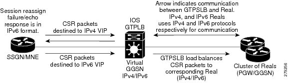
SLB uses the IPv6 address stored in the real(server or gateway) object and performs IPv6 Forwarding Information Base (FIB) lookup and forwards the IPv6 packet from a Serving GPRS Support Node / Mobility Management Entity (SGSN/MME) to the corresponding GTP-SLB virtual IP address. A group of real servers (know as serverfarm) servicing IPv4 and IPv6 traffic is defined and associated to dual-stack virtual server (containing table mapping for both IPv4 and IPv6 addresses). An IPv4 capable real server is selected for a CSR destined to IPv4 Virtual IP (VIP) address and an IPv6 capable real server is selected for a CSR destined to IPv6 VIP address.

Note![]() The DFP weight reporting mechanism by the GGSN/PGW uses the IPv4 transport.
The DFP weight reporting mechanism by the GGSN/PGW uses the IPv4 transport.
Note![]() Probe messages uses IPv4 as transport
Probe messages uses IPv4 as transport
Note![]() A GTPv2 real server can function as a Serving Gateway(SGW) or PDN gateway ( PGW). Only PGW supports GTPv2, V1, V0 requests. SGW supports only GTPv2 requests. A GTPv0 or GTPv1 real cannot process GTPv2 requests. You need to create a separate virtual server for GTPv2 requests and GTPv0/v1 requests, if the real servers are different.
A GTPv2 real server can function as a Serving Gateway(SGW) or PDN gateway ( PGW). Only PGW supports GTPv2, V1, V0 requests. SGW supports only GTPv2 requests. A GTPv0 or GTPv1 real cannot process GTPv2 requests. You need to create a separate virtual server for GTPv2 requests and GTPv0/v1 requests, if the real servers are different.
GTP-SLB Architecture Overview
Figure 23-1 describes GTP-SLB architecture. The three main components (SGSN/MME, GTP-SLB VIP, and GGSN/PGW) of GTP-SLB implementation communicate for:
- Creating PDP session(Create PDP Call Flow).
- Checking the status of Gateway (GTP Echo Call Flow).
- Exchanging notification messages between a SLB and Gateway(GTP Notification Messages).
Figure 23-1 GTP-SLB Architecture
Create PDP Call Flow
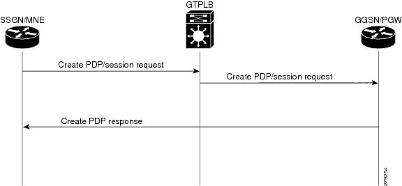
The SGSN/MME initiates the create PDP request with destination address as IPv6 GTP-SLB VIP. The SLB forwards this request to an active IPv6 real (GGSN/PGW) server. The GGSN creates the PDP session and sends the create response directly to SGSN. Figure 23-2 shows the call flow for create PDP session request:
Figure 23-2 Call Flow for Create PDP Session Request
GTP Echo Request Call Flow
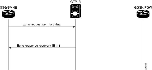
To check the status of gateway, SGSN sends an echo to SLB. The SLB responds to the echo with an IPv6 echo response if the virtual server is active and operational. Figure 23-3 shows the GTP echo request call flow:
Figure 23-3 GTP Echo Request Call Flow
GTP Notification Messages
This section lists the notification messages exchanged between SLB and gateway:
- SLB sends a PDP query request to a real server when the sticky idle timer exceeds the threshold limit. GGSN responds with a PDP status response for the PDP status query. A sticky timer is restarted if the PDP corresponding to International Mobile Subscriber Identity (IMSI) timer is present in the gateway, else the timer and sticky for the IMSI is deleted.
- SGSN sends a delete pdp request to real server (GGSN/PGW). The real server (GGSN/PGW) deletes the PDP context and sends a PDP delete notification to the SLB. On receiving the delete notification, the SLB deletes the sticky entry for the IMSI and the sticky timer instance.
- The real gateway sends a Call Admission Control (CAC) reassign notification to the SLB if it is unable to handle the session. The SLB responds by reassigning the session to another real server.
Restrictions and Usage Guidelines
When configuring GTP-SLB support for IPv6, follow these restrictions and usage guidelines:
- All the IPv4 and IPv6 serverfarms associated to the same vserver should have the same NAT configuration.
- Hot Standby Router Protocol (HSRP) instances (IPv4 and IPv6) for a client facing interface should have the same HSRP state.
- Long Term Evolution (LTE) gateway should be configured with a dual stack.
- PGW/GGSN gateway should always be configured with a IPv4 and IPv6 VIP address of virtual server. This address is used by gateway for notifications.
- The client commands in SLB virtual server configuration mode are not supported for IPv6 addresses.
- The interface between the IOS SLB and gateway must be configured with both IPv6 and IPv4 addresses (dual stack).
Configuring GTP-SLB IPv6 Support
When configuring IPv6 support for GTP load balancing, you need to:
- Specify the IPv6 address for a real server using the real command in SLB serverfarm configuration mode.
- Specify the IPv6 address and the optional IPv6 prefix for a virtual server using the virtual command in SLB virtual server configuration mode.
- Specify the primary IPv6 server farm and the optional backup IPv6 serverfarm using the serverfarm command in SLB virtual server configuration mode.
This process of configuring IPv6 support for GTP-SLB comprises these steps:
Configuring a Serverfarm
SUMMARY STEPS
3.![]() ip slb serverfarm server-farm
ip slb serverfarm server-farm
6.![]() predictor [roundrobin | leastconns | route-map mapname]
predictor [roundrobin | leastconns | route-map mapname]
8.![]() real ipv4-address [ipv6 ipv6-address] [port]
real ipv4-address [ipv6 ipv6-address] [port]
9.![]() faildetect numconns number-of-conns [numclients number-of-clients]
faildetect numconns number-of-conns [numclients number-of-clients]
10.![]() maxclients number-of-conns
maxclients number-of-conns
DETAILED STEPS
Configuring a Virtual Server
SUMMARY STEPS
3.![]() ip slb vserver virtual-server
ip slb vserver virtual-server
4.![]() virtual ip-address [netmask [group]] {esp | gre | protocol} or virtual ip-address [netmask [group]] {tcp | udp} [port | any] [service service] or virtual ip-address [netmask [group]] [ipv6 ipv6-address [prefix ipv6-prefix]] {tcp | udp} [port | any] [service service]
virtual ip-address [netmask [group]] {esp | gre | protocol} or virtual ip-address [netmask [group]] {tcp | udp} [port | any] [service service] or virtual ip-address [netmask [group]] [ipv6 ipv6-address [prefix ipv6-prefix]] {tcp | udp} [port | any] [service service]
5.![]() serverfarm primary-farm [backup backup-farm [sticky] | [map map-id priority priority]] or serverfarm [primary-farm [backup backup-farm ]] [[ipv6-primary ipv6-primary-farm [ipv6-backup ipv6-backup-farm]]] [map map-id priority priority]
serverfarm primary-farm [backup backup-farm [sticky] | [map map-id priority priority]] or serverfarm [primary-farm [backup backup-farm ]] [[ipv6-primary ipv6-primary-farm [ipv6-backup ipv6-backup-farm]]] [map map-id priority priority]
6.![]() access interface [route framed-ip]
access interface [route framed-ip]
8.![]() client {ip-address netmask [exclude] | gtp carrier-code [code]}
client {ip-address netmask [exclude] | gtp carrier-code [code]}
9.![]() delay {duration | radius framed-ip duration}
delay {duration | radius framed-ip duration}
10.![]() gtp notification cac [reassign-count]
gtp notification cac [reassign-count]
13.![]() idle [asn request duration | asn msid msid | gtp imsi duration [query [max-queries]] | gtp request duration | ipmobile request duration| radius {request | framed-ip} duration]
idle [asn request duration | asn msid msid | gtp imsi duration [query [max-queries]] | gtp request duration | ipmobile request duration| radius {request | framed-ip} duration]
14.![]() replicate casa listen-ip remote-ip port [interval] [password [encrypt] secret-string timeout]
replicate casa listen-ip remote-ip port [interval] [password [encrypt] secret-string timeout]
15.![]() replicate interval interval
replicate interval interval
17.![]() sticky {duration [group group-id] [netmask netmask] | asn msid [group group-id] | gtp imsi [group group-id] | radius calling-station-id | radius framed-ip [group group-id] | radius username [msid-cisco] [group group-id]}
sticky {duration [group group-id] [netmask netmask] | asn msid [group group-id] | gtp imsi [group group-id] | radius calling-station-id | radius framed-ip [group group-id] | radius username [msid-cisco] [group group-id]}
DETAILED STEPS
Examples
This example configures the serverfarm to accept only IPv6 addresses:
This example configures the serverfarm to accept IPv4 and IPv6 addresses:
Verification
Run these commands to verify GTP-SLB IPv6 configuration:
Troubleshooting GTP-SLB IPv6 Support Configuration
This section describes how to troubleshoot GTP-SLB IPv6 support configuration. These are some troubleshooting scenarios:
Leastconns is not supported on GTP-SLB as the loadbalancer does not track the number of open PDP sessions in a real server. SLB only load balances the create PDP requests and maintains a session object for each PDP request to ensure request retransmissions are delivered to the assigned real server.
Complete these steps to verify a valid sticky connection:
–![]() Reconfigure all the sticky connections.
Reconfigure all the sticky connections.
–![]() Run the show ip slb reals detail and show ip slb conns commands.
Run the show ip slb reals detail and show ip slb conns commands.
–![]() Check the real server connection counts. Note that the new client connection is assigned to the real server with increased counts.
Check the real server connection counts. Note that the new client connection is assigned to the real server with increased counts.
–![]() Run the show ip slb sticky command to display the sticky relationships stored by IOS SLB.
Run the show ip slb sticky command to display the sticky relationships stored by IOS SLB.
–![]() Check if the real server connection decreased by a single count.
Check if the real server connection decreased by a single count.
–![]() Restart the connection within the sticky timeout value.
Restart the connection within the sticky timeout value.
–![]() Run the show ip slb conns command.
Run the show ip slb conns command.
–![]() Check the real server connection count again and verify that the sticky connection is assigned to the same real server.
Check the real server connection count again and verify that the sticky connection is assigned to the same real server.
Complete these steps to check the servers:
–![]() Check if the number of clients is very less, reduce the numclients value on the faildetect numconns (real server) to an optimum value.
Check if the number of clients is very less, reduce the numclients value on the faildetect numconns (real server) to an optimum value.
–![]() Run the show ip slb reals detail command to view the status of the real servers.
Run the show ip slb reals detail command to view the status of the real servers.
–![]() Check the status and connection counts of the real servers. A failed server shows one of the following statuses: FAILED, TESTING, or READY_TO_TEST.
Check the status and connection counts of the real servers. A failed server shows one of the following statuses: FAILED, TESTING, or READY_TO_TEST.
Note![]() When a real server fails, connections that are assigned but not established (no SYN or ACK is received) are reassigned to another real server on the first inbound SYN after the reassign threshold. However, connections already established to a real server are forwarded to the same real server.
When a real server fails, connections that are assigned but not established (no SYN or ACK is received) are reassigned to another real server on the first inbound SYN after the reassign threshold. However, connections already established to a real server are forwarded to the same real server.
Note![]() For weighted least connections, a new real server starts slowly so that it is not overloaded with new connections. (See the Slow Start section for more information.) The connection count also show dummy connections on the new real server, which IOS SLB uses to artificially inflate the connection counts for the real server during the slow start period.
For weighted least connections, a new real server starts slowly so that it is not overloaded with new connections. (See the Slow Start section for more information.) The connection count also show dummy connections on the new real server, which IOS SLB uses to artificially inflate the connection counts for the real server during the slow start period.
- There is no improvement in failure detection when both faildetect inband and Internet Control Message Protocol (ICMP) probes are configured on a real server.
When a real server is configured with both the ICMP probes and faildetect inband, the faildetect takes precendence. The ICMP probes are health probes, the state of the ICMP probes remain OPERATIONAL as long as the physical interfaces of a real server are accessible. The faildetectinband detects the failure of an application serving a client request on a real server. The ICMP probes transit states when a physical interface failure occurs. It is recommended to have either an ICMP probe or faildetect enabled for real server failure detection.
The no inservice command allows the connection to complete the process before disabling the resource. To stop all the existing connections for an entire firewall farm or virtual server immediately, use the clear ip slb connections command.
- The vserver status, active or standby chassis, configured with GTPLB and HSRP is shown for both the chassis. At an instance both the chasis are shown as active or standby.
Check the configuration for these issues:
–![]() HSRP interface should be configured with a unique group number if more than one HSRP instances are configured.
HSRP interface should be configured with a unique group number if more than one HSRP instances are configured.
–![]() HSRP group name is casesensitive and should be unique.
HSRP group name is casesensitive and should be unique.
- You can load-balance a packet through layer 3 and non-layer 2 adjacent connections in the Nat server serverfarm configuration.
- Dispatched mode does not function in the GGSN(PGW).
Verify that the GGSN is configured with the VIP address as the loopback.
Verify that the virtual server address with next hop IP address is configured on the gateway.
The address specified while creating the PDP request from SGPRS might not match the address in the pool defined.
 Feedback