- Preface
- Product Overview
- Configuring the Router for the First Time
- Configuring a Supervisor Engine 720
- Configuring a Route Switch Processor 720
- Configuring NSF with SSO Supervisor Engine Redundancy
- ISSU and eFSU on Cisco 7600 Series Routers
- Configuring RPR and RPR+ Supervisor Engine Redundancy
- Configuring Interfaces
- Configuring a Supervisor Engine 32
- Configuring LAN Ports for Layer 2 Switching
- Configuring Flex Links
- Configuring EtherChannels
- Configuring VTP
- Configuring VLANs
- Configuring Private VLANs
- Configuring Cisco IP Phone Support
- Configuring IEEE 802.1Q Tunneling
- Configuring Layer 2 Protocol Tunneling
- Configuring L2TPv3
- Configuring STP and MST
- Configuring Optional STP Features
- Configuring Layer 3 Interfaces
- Configuring GTP-SLB IPV6 Support
- IP Subscriber Awareness over Ethernet
- Configuring UDE and UDLR
- Configuring Multiprotocol Label Switching on the PFC
- Configuring IPv4 Multicast VPN Support
- Configuring Multicast VPN Extranet Support
- Configuring IP Unicast Layer 3 Switching
- Configuring IPv6 Multicast PFC3 and DFC3 Layer 3 Switching
- Configuring IPv4 Multicast Layer 3 Switching
- Configuring MLDv2 Snooping for IPv6 Multicast Traffic
- Configuring IGMP Snooping for IPv4 Multicast Traffic
- Configuring PIM Snooping
- Configuring Network Security
- Understanding Cisco IOS ACL Support
- Configuring VRF aware 6RD Tunnels
- Configuring VLAN ACLs
- Private Hosts (Using PACLs)
- Configuring IPv6 PACL
- IPv6 First-Hop Security Features
- Configuring Online Diagnostics
- Configuring Denial of Service Protection
- Configuring DHCP Snooping
- Configuring Dynamic ARP Inspection
- Configuring Traffic Storm Control
- Unknown Unicast Flood Blocking
- Configuring PFC QoS
- Configuring PFC QoS Statistics Data Export
- Configuring MPLS QoS on the PFC
- Configuring LSM MLDP based MVPN Support
- Configuring IEEE 802.1X Port-Based Authentication
- Configuring IEEE 802.1ad
- Configuring Port Security
- Configuring UDLD
- Configuring NetFlow and NDE
- Configuring Local SPAN, RSPAN, and ERSPAN
- Configuring SNMP IfIndex Persistence
- Power Management and Environmental Monitoring
- Configuring Web Cache Services Using WCCP
- Using the Top N Utility
- Using the Layer 2 Traceroute Utility
- Configuring Bidirectional Forwarding and Detection over Switched Virtual Interface
- Configuring Call Home
- Configuring IPv6 Policy Based Routing
- Using the Mini Protocol Analyzer
- Configuring Resilient Ethernet Protocol
- Configuring Synchronous Ethernet
- Configuring Link State Tracking
- Configuring BGP PIC Edge and Core for IP and MPLS
- Configuring VRF aware IPv6 tunnels over IPv4 transport
- ISIS IPv4 Loop Free Alternate Fast Reroute (LFA FRR)
- Multicast Service Reflection
- Y.1731 Performance Monitoring
- Online Diagnostic Tests
- Acronyms
- Cisco IOS Release 15S Software Images
- Index
Configuring Traffic Storm Control
This chapter describes how to configure the traffic storm control feature on the Cisco 7600 series routers.

Note For complete syntax and usage information for the commands used in this chapter, refer to the Cisco 7600 Series Routers Command References at this URL:
http://www.cisco.com/en/US/products/hw/routers/ps368/prod_command_reference_list.html
Understanding Traffic Storm Control
A traffic storm occurs when packets flood the LAN, creating excessive traffic and degrading network performance. The traffic storm control feature prevents LAN ports from being disrupted by a broadcast, multicast, or unicast traffic storm on physical interfaces.
Traffic storm control (also called traffic suppression) monitors incoming traffic levels over a 1-second traffic storm control interval and, during the interval, compares the traffic level with the traffic storm control level that you configure. The traffic storm control level is a percentage of the total available bandwidth of the port. Each port has a single traffic storm control level that is used for all types of traffic (broadcast, multicast, and unicast).
Traffic storm control monitors the level of each traffic type for which you enable traffic storm control in 1-second traffic storm control intervals. Within an interval, when the ingress traffic for which traffic storm control is enabled reaches the traffic storm control level that is configured on the port, traffic storm control drops the traffic until the traffic storm control interval ends.
Figure 46-1 shows the broadcast traffic patterns on a LAN interface over a given interval. In this example, traffic storm control occurs between times T1 and T2 and between T4 and T5. During those intervals, the amount of broadcast traffic exceeded the configured threshold.
Figure 46-1 Broadcast Suppression
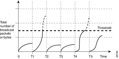
The traffic storm control threshold numbers and the time interval combination make the traffic storm control algorithm work with different levels of granularity. A higher threshold allows more packets to pass through.
Traffic storm control on the Cisco 7600 series routers is implemented in hardware. The traffic storm control circuitry monitors packets passing from a LAN interface to the switching bus. Using the Individual/Group bit in the packet destination address, the traffic storm control circuitry determines if the packet is unicast or broadcast, keeps track of the current count of packets within the 1-second interval, and when a threshold is reached, filters out subsequent packets.
Because hardware traffic storm control uses a bandwidth-based method to measure traffic, the most significant implementation factor is setting the percentage of total available bandwidth that can be used by controlled traffic. Because packets do not arrive at uniform intervals, the 1-second interval during which controlled traffic activity is measured can affect the behavior of traffic storm control.
The following are examples of traffic storm control behavior:
- If you enable broadcast traffic storm control, and broadcast traffic exceeds the level within a 1-second traffic storm control interval, traffic storm control drops all broadcast traffic until the end of the traffic storm control interval.
- If you enable broadcast and multicast traffic storm control, and the combined broadcast and multicast traffic exceeds the level within a 1-second traffic storm control interval, traffic storm control drops all broadcast and multicast traffic until the end of the traffic storm control interval.
- If you enable broadcast and multicast traffic storm control, and broadcast traffic exceeds the level within a 1-second traffic storm control interval, traffic storm control drops all broadcast and multicast traffic until the end of the traffic storm control interval.
- If you enable broadcast and multicast traffic storm control, and multicast traffic exceeds the level within a 1-second traffic storm control interval, traffic storm control drops all broadcast and multicast traffic until the end of the traffic storm control interval.
Detecting and Controlling Traffic Storms
The mechanism to detect and control such storm event(s) is referred to as storm control or broadcast suppression.
A traffic storm is detected when the following occurs:
- The port receives multicast and broadcast traffic more than the bandwidth value as configured in the storm-control command.
- The value of the TotalSuppDiscards counter displayed in the show interface gig < slot/port > counters storm-control command increments.
In Cisco IOS Release 15.0(1)S the following storm control feature enhancements are covered on the 67xx, 6196, ES20 and ES+ line cards:
- Port-channel interfaces: Support for port-channel interfaces.
- Shutdown: When a storm is detected and the storm traffic exceeds the accepted threshold, the affected interface moves to error disable state. The traffic threshold is calculated as a percentage of the total bandwidth of the port (%BW). Use the error disable detection and the recovery feature, or the shut/no shut command to re-enable the port on the affected interface.
- Trap: An SNMP trap can be sent when a storm is detected.
Default Traffic Storm Control Configuration
Configuration Guidelines and Restrictions
When configuring traffic storm control, follow these guidelines and restrictions:
- Storm control for multicast and unicast does not work on WS-X6148-RJ-45, WS-X6148-RJ21, WS-X6196-RJ21, 6196-21AF, WS-X6148X2-RJ-45, WS-X6548-RJ-45, WS-X6548-RJ21, these line cards (with Port-ASICs COIL/Pentamak) support broadcast storm control only.
- The WS-X6548-GE-TX, WS-X6548V-GE-TX, WS-X6148-GE-TX, and WS-X6148V-GE-TX switching modules do not support traffic storm control.
- ES+ line card does not support storm control for unicast packets
- The router supports multicast and unicast traffic storm control only on Gigabit and 10 Gigabit Ethernet LAN ports.
- The router supports broadcast traffic storm control on all LAN ports.
- Except for BPDUs, traffic storm control does not differentiate between control traffic and data traffic.
- When multicast suppression is enabled, traffic storm control suppresses BPDUs when the multicast suppression threshold is exceeded on these modules:
When multicast suppression is enabled on the listed modules, do not configure traffic storm control on STP-protected ports that need to receive BPDUs. Except on the listed modules, traffic storm control does not suppress BPDUs.
- The 6196 line card supports suppression for broadcast traffic and not multicast traffic.
- Storm control on port-channel interfaces of the ES20 and ES+ line cards is supported in Cisco IOS Release 15.0(1)S.
- Unicast traffic is supported on 67XX line cards, but not supported on ES20 and ES40 line cards.
- Any addition or change made to the storm control configuration on port-channel interfaces is automatically updated on the port-channel member links.
- Storm control configuration or deletion is not allowed on member links.
- You can add an interface to a port-channel if the storm control configuration on the interface and the port-channel are alike.
–![]() You can either club member-links to form a port-channel and then configure the port-channel or change the storm control configuration on the interface to match with the port-channel, before adding it to the port-channel.
You can either club member-links to form a port-channel and then configure the port-channel or change the storm control configuration on the interface to match with the port-channel, before adding it to the port-channel.
Enabling Traffic Storm Control
To enable traffic storm control, perform this task:
|
|
|
|
|---|---|---|
Router(config)# interface {{ type 1 slot/port } | { port-channel number }} |
||
Router(config)# snmp-server enable traps storm-control trap-rate traps per minute |
(Optional) Enables SNMP storm control trap parameters. The trap-rate range is 0 to 1000 traps per minute. However, the number of traps generated for storm control cannot exceed six per minute (by design). |
|
Router(config-if)# storm-control broadcast level level [. level ] |
Enables broadcast traffic storm control on the interface, configures the traffic storm control level, and applies the traffic storm control level to all traffic storm control modes enabled on the interface. |
|
Router(config-if)# storm-control multicast level level [. level ] |
Enables multicast traffic storm control on the interface, configures the traffic storm control level, and applies the traffic storm control level to all traffic storm control modes enabled on the interface. Note The storm-control multicast command is supported only on Gigabit Ethernet interfaces. |
|
Router(config-if)# storm-control unicast level level [. level ] |
Enables unicast traffic storm control on the interface, configures the traffic storm control level, and applies the traffic storm control level to all traffic storm control modes enabled on the interface. Note The storm-control unicast command is supported only on Gigabit Ethernet interfaces. |
|
|
1.type = ethernet, fastethernet, gigabitethernet, or tengigabitethernet |
When configuring the traffic storm control level, note the following information:
- You can configure traffic storm control on an EtherChannel (a port channel interface).
- Do not configure traffic storm control on ports that are members of an EtherChannel. Configuring traffic storm control on ports that are configured as members of an EtherChannel puts the ports into a suspended state.
- Specify the level as a percentage of the total interface bandwidth:
–![]() The level can be from 0 to 100.
The level can be from 0 to 100.
–![]() The optional fraction of a level can be from 0 to 99.
The optional fraction of a level can be from 0 to 99.
–![]() 100 percent means no traffic storm control.
100 percent means no traffic storm control.
–![]() 0.0 percent suppresses all traffic.
0.0 percent suppresses all traffic.
Note![]() On these modules, following levels suppress all traffic:
On these modules, following levels suppress all traffic:
—WS-X6704-10GE: less than 0.33 percent round to zero
—WS-X6748-SFP: less than 0.03 percent
—WS-X6748-GE-TX: depends on speed:
if 10 Mbps: less than 0.33 percent round to zero
if 100 Mbps: less than 0.03 percent round to zero
if 1Gbps: no restriction
Because of hardware limitations and the method by which packets of different sizes are counted, the level percentage is an approximation. Depending on the sizes of the frames making up the incoming traffic, the actual enforced level might differ from the configured level by several percentage points.
This example shows how to enable multicast traffic storm control on Gigabit Ethernet interface 3/16 and how to configure the traffic storm control level at 70.5 percent. This configuration applies the traffic storm control level to all traffic storm control modes enabled on Gigabit Ethernet interface 3/16:
Displaying Traffic Storm Control Settings
To display traffic storm control information, use the commands described in Table 46-1 .
|
|
|
|---|---|
Router# show interfaces [{ type 2 slot/port } | { port-channel number }] switchport |
Displays the administrative and operational status of all Layer 2 LAN ports or the specified Layer 2 LAN port. |
Router# show interfaces [{ type 1 slot/port } | { port-channel number }] counters storm-control Router# show interfaces counters storm-control [ module slot_number ] |
Displays the total number of packets discarded for all three traffic storm control modes, on all interfaces or on the specified interface. |
|
2.type = ethernet, fastethernet, gigabitethernet, or tengigabitethernet |
Note![]() The show interfaces [{interface_type slot/port} | {port-channel number}] counters command does not display the discard count. You must the storm-control keyword to display the discard count.
The show interfaces [{interface_type slot/port} | {port-channel number}] counters command does not display the discard count. You must the storm-control keyword to display the discard count.
 Feedback