- Preface
- Product Overview
- Configuring the Router for the First Time
- Configuring a Supervisor Engine 720
- Configuring a Route Switch Processor 720
- Configuring NSF with SSO Supervisor Engine Redundancy
- ISSU and eFSU on Cisco 7600 Series Routers
- Configuring RPR and RPR+ Supervisor Engine Redundancy
- Configuring Interfaces
- Configuring a Supervisor Engine 32
- Configuring LAN Ports for Layer 2 Switching
- Configuring Flex Links
- Configuring EtherChannels
- Configuring VTP
- Configuring VLANs
- Configuring Private VLANs
- Configuring Cisco IP Phone Support
- Configuring IEEE 802.1Q Tunneling
- Configuring Layer 2 Protocol Tunneling
- Configuring L2TPv3
- Configuring STP and MST
- Configuring Optional STP Features
- Configuring Layer 3 Interfaces
- Configuring GTP-SLB IPV6 Support
- IP Subscriber Awareness over Ethernet
- Configuring UDE and UDLR
- Configuring Multiprotocol Label Switching on the PFC
- Configuring IPv4 Multicast VPN Support
- Configuring Multicast VPN Extranet Support
- Configuring IP Unicast Layer 3 Switching
- Configuring IPv6 Multicast PFC3 and DFC3 Layer 3 Switching
- Configuring IPv4 Multicast Layer 3 Switching
- Configuring MLDv2 Snooping for IPv6 Multicast Traffic
- Configuring IGMP Snooping for IPv4 Multicast Traffic
- Configuring PIM Snooping
- Configuring Network Security
- Understanding Cisco IOS ACL Support
- Configuring VRF aware 6RD Tunnels
- Configuring VLAN ACLs
- Private Hosts (Using PACLs)
- Configuring IPv6 PACL
- IPv6 First-Hop Security Features
- Configuring Online Diagnostics
- Configuring Denial of Service Protection
- Configuring DHCP Snooping
- Configuring Dynamic ARP Inspection
- Configuring Traffic Storm Control
- Unknown Unicast Flood Blocking
- Configuring PFC QoS
- Configuring PFC QoS Statistics Data Export
- Configuring MPLS QoS on the PFC
- Configuring LSM MLDP based MVPN Support
- Configuring IEEE 802.1X Port-Based Authentication
- Configuring IEEE 802.1ad
- Configuring Port Security
- Configuring UDLD
- Configuring NetFlow and NDE
- Configuring Local SPAN, RSPAN, and ERSPAN
- Configuring SNMP IfIndex Persistence
- Power Management and Environmental Monitoring
- Configuring Web Cache Services Using WCCP
- Using the Top N Utility
- Using the Layer 2 Traceroute Utility
- Configuring Bidirectional Forwarding and Detection over Switched Virtual Interface
- Configuring Call Home
- Configuring IPv6 Policy Based Routing
- Using the Mini Protocol Analyzer
- Configuring Resilient Ethernet Protocol
- Configuring Synchronous Ethernet
- Configuring Link State Tracking
- Configuring BGP PIC Edge and Core for IP and MPLS
- Configuring VRF aware IPv6 tunnels over IPv4 transport
- ISIS IPv4 Loop Free Alternate Fast Reroute (LFA FRR)
- Multicast Service Reflection
- Y.1731 Performance Monitoring
- Online Diagnostic Tests
- Acronyms
- Cisco IOS Release 15S Software Images
- Index
Configuring IP Unicast Layer 3 Switching
This chapter describes how to configure IP unicast Layer 3 switching on Cisco 7600 series routers.

Note For complete syntax and usage information for the commands used in this chapter, refer to these publications:
http://www.cisco.com/en/US/products/hw/routers/ps368/prod_command_reference_list.html
http://www.cisco.com/univercd/cc/td/doc/product/software/ios122/122cgcr/index.htm
This chapter consists of these sections:
- Understanding How Layer 3 Switching Works
- Default Hardware Layer 3 Switching Configuration
- Configuration Guidelines and Restrictions
- Configuring Hardware Layer 3 Switching
- Displaying Hardware Layer 3 Switching Statistics
Note ●![]() IPX traffic is fast switched on the MSFC. For more information, refer to this URL:
IPX traffic is fast switched on the MSFC. For more information, refer to this URL:
http://www.cisco.com/univercd/cc/td/doc/product/software/ios122/122cgcr/fatipx_c/index.htm
- For information about IP multicast Layer 3 switching, see Chapter31, “Configuring IPv4 Multicast Layer 3 Switching”
Understanding How Layer 3 Switching Works
These sections describe Layer 3 switching:
Understanding Hardware Layer 3 Switching
Hardware Layer 3 switching allows the PFC and DFCs, instead of the MSFC, to forward IP unicast traffic between subnets. Hardware Layer 3 switching provides wire-speed forwarding on the PFC and DFCs, instead of in software on the MSFC. Hardware Layer 3 switching requires minimal support from the MSFC. The MSFC routes any traffic that cannot be hardware Layer 3 switched.
Hardware Layer 3 switching supports the routing protocols configured on the MSFC. Hardware Layer 3 switching does not replace the routing protocols configured on the MSFC.
Hardware Layer 3 switching runs equally on the PF3 and DFCs to provide IP unicast Layer 3 switching locally on each module. Hardware Layer 3 switching provides the following functions:
- Hardware access control list (ACL) switching for policy-based routing (PBR)
- Hardware NetFlow switching for TCP intercept, reflexive ACL forwarding decisions
- Hardware Cisco Express Forwarding (CEF) switching for all other IP unicast traffic
Hardware Layer 3 switching on the PFC supports modules that do not have a DFC. The MSFC forwards traffic that cannot be Layer 3 switched.
Traffic is hardware Layer 3 switched after being processed by access lists and quality of service (QoS).
Hardware Layer 3 switching makes a forwarding decision locally on the ingress-port module for each packet and sends the rewrite information for each packet to the egress port, where the rewrite occurs when the packet is transmitted from the Cisco 7600 series router.
Hardware Layer 3 switching generates flow statistics for Layer 3-switched traffic. Hardware Layer 3 flow statistics can be used for NetFlow Data Export (NDE). (See Chapter 56, “Configuring NetFlow and NDE”.)
Understanding Layer 3-Switched Packet Rewrite
When a packet is Layer 3 switched from a source in one subnet to a destination in another subnet, the Cisco 7600 series router performs a packet rewrite at the egress port based on information learned from the MSFC so that the packets appear to have been routed by the MSFC.
Packet rewrite alters five fields:
- Layer 2 (MAC) destination address
- Layer 2 (MAC) source address
- Layer 3 IP Time to Live (TTL)
- Layer 3 checksum
- Layer 2 (MAC) checksum (also called the frame checksum or FCS)
Note![]() Packets are rewritten with the encapsulation appropriate for the next-hop subnet.
Packets are rewritten with the encapsulation appropriate for the next-hop subnet.
If Source A and Destination B are in different subnets and Source A sends a packet to the MSFC to be routed to Destination B, the router recognizes that the packet was sent to the Layer 2 (MAC) address of the MSFC.
To perform Layer 3 switching, the router rewrites the Layer 2 frame header, changing the Layer 2 destination address to the Layer 2 address of Destination B and the Layer 2 source address to the Layer 2 address of the MSFC. The Layer 3 addresses remain the same.
In IP unicast and IP multicast traffic, the router decrements the Layer 3 TTL value by 1 and recomputes the Layer 3 packet checksum. The router recomputes the Layer 2 frame checksum and forwards (or, for multicast packets, replicates as necessary) the rewritten packet to Destination B’s subnet.
A received IP unicast packet is formatted (conceptually) as follows:
|
|
|
|
|
||||
|---|---|---|---|---|---|---|---|
After the router rewrites an IP unicast packet, it is formatted (conceptually) as follows:
|
|
|
|
|
||||
|---|---|---|---|---|---|---|---|
Hardware Layer 3 Switching Examples
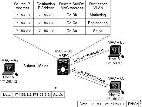
Figure 29-1 shows a simple network topology. In this example, Host A is on the Sales VLAN (IP subnet 171.59.1.0), Host B is on the Marketing VLAN (IP subnet 171.59.3.0), and Host C is on the Engineering VLAN (IP subnet 171.59.2.0).
When Host A initiates an HTTP file transfer to Host C, Hardware Layer 3 switching uses the information in the local forwarding information base (FIB) and adjacency table to forward packets from Host A to Host C.
Figure 29-1 Hardware Layer 3 Switching Example Topology
Default Hardware Layer 3 Switching Configuration
Table 29-1 shows the default hardware Layer 3 switching configuration.
|
|
|
|---|---|
Cisco IOS dCEF1 enable state on MSFC |
|
|
Configuration Guidelines and Restrictions
Follow these guidelines and restrictions when configuring hardware Layer 3 switching:
Configuring Hardware Layer 3 Switching
Note![]() For information on configuring unicast routing on the MSFC, see Chapter22, “Configuring Layer 3 Interfaces”
For information on configuring unicast routing on the MSFC, see Chapter22, “Configuring Layer 3 Interfaces”
Hardware Layer 3 switching is permanently enabled. No configuration is required.
To display information about Layer 3-switched traffic, perform this task:
|
|
|
|---|---|
Router# show interface {{ type 2 slot/port } | { port-channel number }} | begin L3 |
|
2.type = ethernet, fastethernet, gigabitethernet, or tengigabitethernet |
This example shows how to display information about hardware Layer 3-switched traffic on Fast Ethernet port 3/3:
Note![]() The Layer 3 switching packet count is updated approximately every five seconds.
The Layer 3 switching packet count is updated approximately every five seconds.
Cisco IOS CEF and dCEF are permanently enabled. No configuration is required to support hardware Layer 3 switching.
With a PFC (and DFCs, if present), hardware Layer 3 switching uses per-flow load balancing based on IP source and destination addresses. Per-flow load balancing avoids the packet reordering that can be necessary with per-packet load balancing. For any given flow, all PFC- and DFC-equipped switches make exactly the same load-balancing decision, which can result in nonrandom load balancing.
The Cisco IOS CEF ip load-sharing per-packet, ip cef accounting per-prefix, and ip cef accounting non-recursive commands are not supported on the C7600 series routers.
For information about Cisco IOS CEF and dCEF on the MSFC, refer to these publications:
http://www.cisco.com/univercd/cc/td/doc/product/software/ios122/122cgcr/fswtch_c/swprt1/index.htm
http://www.cisco.com/en/US/docs/ios/12_2/switch/command/reference/fswtch_r.html
Displaying Hardware Layer 3 Switching Statistics
Hardware Layer 3 switching statistics are obtained on a per-VLAN basis.
To display hardware Layer 3 switching statistics, perform this task:
|
|
|
|---|---|
Router# show interfaces {{ type 3 slot/port } | { port-channel number }} |
|
3.type = ethernet, fastethernet, gigabitethernet, or tengigabitethernet |
This example shows how to display hardware Layer 3 switching statistics:
To display adjacency table information, perform this task:
|
|
|
|---|---|
Router# show adjacency [{{ type 4 slot/port } | { port-channel number }} | detail | internal | summary ] |
Displays adjacency table information. The optional detail keyword displays detailed adjacency information, including Layer 2 information. |
|
4.type = ethernet, fastethernet, gigabitethernet, or tengigabitethernet |
This example shows how to display adjacency statistics:
Note![]() Adjacency statistics are updated approximately every 60 seconds.
Adjacency statistics are updated approximately every 60 seconds.
 Feedback