- Preface
- Product Overview
- Configuring the Router for the First Time
- Configuring a Supervisor Engine 720
- Configuring a Route Switch Processor 720
- Configuring NSF with SSO Supervisor Engine Redundancy
- ISSU and eFSU on Cisco 7600 Series Routers
- Configuring RPR and RPR+ Supervisor Engine Redundancy
- Configuring Interfaces
- Configuring a Supervisor Engine 32
- Configuring LAN Ports for Layer 2 Switching
- Configuring Flex Links
- Configuring EtherChannels
- Configuring VTP
- Configuring VLANs
- Configuring Private VLANs
- Configuring Cisco IP Phone Support
- Configuring IEEE 802.1Q Tunneling
- Configuring Layer 2 Protocol Tunneling
- Configuring L2TPv3
- Configuring STP and MST
- Configuring Optional STP Features
- Configuring Layer 3 Interfaces
- Configuring GTP-SLB IPV6 Support
- IP Subscriber Awareness over Ethernet
- Configuring UDE and UDLR
- Configuring Multiprotocol Label Switching on the PFC
- Configuring IPv4 Multicast VPN Support
- Configuring Multicast VPN Extranet Support
- Configuring IP Unicast Layer 3 Switching
- Configuring IPv6 Multicast PFC3 and DFC3 Layer 3 Switching
- Configuring IPv4 Multicast Layer 3 Switching
- Configuring MLDv2 Snooping for IPv6 Multicast Traffic
- Configuring IGMP Snooping for IPv4 Multicast Traffic
- Configuring PIM Snooping
- Configuring Network Security
- Understanding Cisco IOS ACL Support
- Configuring VRF aware 6RD Tunnels
- Configuring VLAN ACLs
- Private Hosts (Using PACLs)
- Configuring IPv6 PACL
- IPv6 First-Hop Security Features
- Configuring Online Diagnostics
- Configuring Denial of Service Protection
- Configuring DHCP Snooping
- Configuring Dynamic ARP Inspection
- Configuring Traffic Storm Control
- Unknown Unicast Flood Blocking
- Configuring PFC QoS
- Configuring PFC QoS Statistics Data Export
- Configuring MPLS QoS on the PFC
- Configuring LSM MLDP based MVPN Support
- Configuring IEEE 802.1X Port-Based Authentication
- Configuring IEEE 802.1ad
- Configuring Port Security
- Configuring UDLD
- Configuring NetFlow and NDE
- Configuring Local SPAN, RSPAN, and ERSPAN
- Configuring SNMP IfIndex Persistence
- Power Management and Environmental Monitoring
- Configuring Web Cache Services Using WCCP
- Using the Top N Utility
- Using the Layer 2 Traceroute Utility
- Configuring Bidirectional Forwarding and Detection over Switched Virtual Interface
- Configuring Call Home
- Configuring IPv6 Policy Based Routing
- Using the Mini Protocol Analyzer
- Configuring Resilient Ethernet Protocol
- Configuring Synchronous Ethernet
- Configuring Link State Tracking
- Configuring BGP PIC Edge and Core for IP and MPLS
- Configuring VRF aware IPv6 tunnels over IPv4 transport
- ISIS IPv4 Loop Free Alternate Fast Reroute (LFA FRR)
- Multicast Service Reflection
- Y.1731 Performance Monitoring
- Online Diagnostic Tests
- Acronyms
- Cisco IOS Release 15S Software Images
- Index
- PFC MPLS Label Switching
- Multicast Adjacency Allocation
- VPN Switching on the PFC
- Any Transport over MPLS
Configuring Multiprotocol Label Switching on the PFC
This chapter describes how to configure Multiprotocol Label Switching (MPLS) on the Cisco 7600 PFC card. The information in this chapter describes MPLS operation on the PFC3B, PFC3BXL, PFC3C, and PFC3CXL cards. Unless otherwise noted, MPLS operation is the same on all of these PFC cards.

Note For complete syntax and usage information for the commands used in this chapter, see these publications:
http://www.cisco.com/en/US/products/hw/routers/ps368/prod_command_reference_list.html
http://www.cisco.com/univercd/cc/td/doc/product/software/ios122/122cgcr/index.htm
PFC MPLS Label Switching
These sections describe MPLS label switching:
- Understanding MPLS
- Understanding MPLS Label Switching
- Supported Hardware Features
- Supported Cisco IOS Features
- MPLS Guidelines and Restrictions
- Configuring MPLS
- MPLS Per-Label Load Balancing
- MPLS Configuration Examples
- Scalable EoMPLS and Port-mode EoMPLS
- Sample Configuration for SwEoMPLS and VPLS
Understanding MPLS
MPLS uses label switching to forward packets over various link-level technologies such as Packet-over-SONET (POS), Frame Relay, ATM, and Ethernet. Labels are assigned to packets based on groupings or forwarding equivalence classes (FECs). The label is added between the Layer 2 and the Layer 3 header.
In an MPLS network, the label edge router (LER) performs a label lookup of the incoming label, swaps the incoming label with an outgoing label, and sends the packet to the next hop at the label switch router (LSR). Labels are imposed (pushed) on packets only at the ingress edge of the MPLS network and are removed (popped) at the egress edge. The core network LSRs (provider, or P routers) read the labels, apply the appropriate services, and forward the packets based on the labels.
Incoming labels are aggregate or nonaggregate. The aggregate label indicates that the arriving MPLS packet must be switched through an IP lookup to find the next hop and the outgoing interface. The nonaggregate label indicates that the packet contains the IP next hop information.
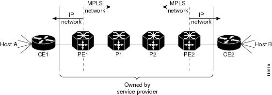
Figure 26-1 shows an MPLS network of a service provider that connects two sites of a customer network.
For additional information on MPLS, see this publication:
http://www.cisco.com/univercd/cc/td/doc/product/software/ios122/122cgcr/fswtch_c/swprt3/xcftagov.htm
Understanding MPLS Label Switching
The PFC supports Layer 3 Multiprotocol Label Switching (MPLS) virtual private networks (VPNs), and Layer 2 Ethernet over MPLS (EoMPLS), with quality of service (QoS) and security.
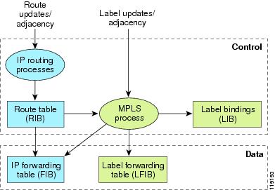
The MSFC on the supervisor engine performs Layer 3 control-plane functions, including address resolution and routing protocols. The MSFC processes information from the Routing and Label Distribution Protocols and builds the IP forwarding (FIB) table and the label forwarding (LFIB) table. The MSFC distributes the information in both tables to the PFC.
The PFC receives the information and creates its own copies of the FIB and LFIB tables. Together, these tables comprise the FIB TCAM. The DFC looks up incoming IP packets and labeled packets against the FIB TCAM table. The lookup result is the pointer to a particular adjacency entry. It is the adjacency entry that contains appropriate information for label pushing (for IP to MPLS path), label swapping (for MPLS to MPLS path), label popping (for MPLS to IP path), and encapsulation.
Figure 26-2 shows the various functional blocks on the PFC that support MPLS label switching. Routing protocol generates a routing information base (RIB) that is used for forwarding IP and MPLS data packets. For Cisco Express Forwarding (CEF), necessary routing information from the RIB is extracted and built into a forwarding information base (FIB). The label distribution protocol (LDP) obtains routes from the RIB and distributes the label across a label switch path to build a label forwarding information base (LFIB) in each of the LSRs and LERs.
Figure 26-2 MPLS Forwarding, Control and Data Planes
IP to MPLS
At the ingress to the MPLS network, the PFC examines the IP packets and performs a route lookup in the FIB TCAM. The lookup result is the pointer to a particular adjacency entry. The adjacency entry contains the appropriate information for label pushing (for IP to MPLS path) and encapsulation. The PFC generates a result containing the imposition label(s) needed to switch the MPLS packet.
Note![]() If MPLS load sharing is configured, the adjacency may point to a load-balanced path. See “Basic MPLS Load Balancing” section.
If MPLS load sharing is configured, the adjacency may point to a load-balanced path. See “Basic MPLS Load Balancing” section.
MPLS to MPLS
At the core of an MPLS network, the PFC uses the topmost label to perform a lookup in the FIB TCAM. The successful lookup points to an adjacency that swaps the top label in the packet with a new label as advertised by the downstream label switch router (LSR). If the router is the penultimate hop LSR router (the upstream LSR next to the egress LER), the adjacency instructs the PFCBXL or PFC3CXL to pop the topmost label, resulting in either an MPLS packet with the remaining label for any VPN or AToM use or a native IP packet.
MPLS to IP
At the egress of the MPLS network there are several possibilities.
For a native IP packet (when the penultimate router has popped the label), the PFC performs a route lookup in the FIB TCAM.
For a MPLS VPN packet, after the Interior Gateway Protocol (IGP) label is popped at penultimate router, the VPN label remains. The operation that the PFC performs depends on the VPN label type. Packets carrying aggregate labels require a second lookup based on the IP header after popping the aggregate label. For a nonaggregate label, the PFC performs a route lookup in the FIB TCAM to obtain the IP next hop information.
For the case of a packet with an IGP label and a VPN label, when there is no penultimate hop popping (PHP), the packet carries the explicit-null label on top of the VPN label. The PFC looks up the top label in the FIB TCAM and recirculates the packet. Then the PFC handles the remaining label as described in the preceding paragraph, depending on whether it is an aggregate or nonaggregate label.
Packets with the explicit-null label for the cases of EoMPLS, MPLS, and MPLS VPN an MPLS are handled the same way.
MPLS VPN Forwarding
There are two types of VPN labels: aggregate labels for directly connected network or aggregate routes, and nonaggregate labels. Packets carrying aggregate labels require a second lookup based on the IP header after popping the aggregate label. The VPN information (VPN-IPv4 address, extended community, and label) is distributed through the Multiprotocol-Border Gateway Protocol (MP-BGP).
Recirculation
In certain cases, the PFC provides the capability to recirculate the packets. Recirculation can be used to perform additional lookups in the ACL or QoS TCAMs, the Netflow table, or the FIB TCAM table. Recirculation is necessary in these situations:
- To push more than three labels on imposition
- To pop more than two labels on disposition
- To pop an explicit null top label
- When the VPN Routing and Forwarding (VRF) number is more than 511
- For IP ACL on the egress interface (for nonaggregate (per-prefix) labels only)
Packet recirculation occurs only on a particular packet flow; other packet flows are not affected.The rewrite of the packet occurs on the modules; the packets are then forwarded back to the PFC for additional processing.
Supported Hardware Features
The following hardware features are supported:
- Label operation— Any number of labels can be pushed or popped, although for best results, up to three labels can be pushed, and up to two labels can be popped in the same operation.
- IP to MPLS path—IP packets can be received and sent to the MPLS path.
- MPLS to IP path—Labeled packets can be received and sent to the IP path.
- MPLS to MPLS path—Labeled packets can be received and sent to the label path.
- MPLS Traffic Engineering (MPLS TE)—Enables an MPLS backbone to replicate and expand the traffic engineering capabilities of Layer 2 ATM and Frame Relay networks.
- Time to live (TTL) operation—At the ingress edge of the MPLS network, the TTL value in the MPLS frame header can be received from either the TTL field of the IP packet header or the user-configured value from the adjacency entry. At the egress of the MPLS network, the final TTL equals the minimum (label TTL and IP TTL)-1.
Note![]() With the Uniform mode, the TTL is taken from the IP TTL; with the Pipe mode, a value of 255, taken from the hardware register, is used for the outgoing label.
With the Uniform mode, the TTL is taken from the IP TTL; with the Pipe mode, a value of 255, taken from the hardware register, is used for the outgoing label.
- QoS—Information on Differentiated Services (DiffServ) and ToS from IP packets can be mapped to MPLS EXP field.
- MPLS/VPN Support—Up to 1024 VRFs can be supported (over 511 VRFs requires recirculation).
- Ethernet over MPLS—The Ethernet frame can be encapsulated at the ingress to the MPLS domain and the Ethernet frame can be decapsulated at the egress.
- Packet recirculation—The PFC provides the capability to recirculate the packets. See the “Recirculation” section.
- Configuration of MPLS switching is supported on VLAN interfaces with the mpls ip command.
Supported Cisco IOS Features
The following Cisco IOS software features are supported on the PFC:
Note![]() Multi-VPN Routing and Forwarding (VRF) for CE Routers (VRF Lite) is supported with the following features: IPv4 forwarding between VRFs interfaces, IPv4 ACLs, and IPv4 HSRP.
Multi-VPN Routing and Forwarding (VRF) for CE Routers (VRF Lite) is supported with the following features: IPv4 forwarding between VRFs interfaces, IPv4 ACLs, and IPv4 HSRP.
- Multi-VRF for CE Routers (VRF Lite)—VRF-lite is a feature that enables a service provider to support two or more VPNs (using only VRF-based IPv4), where IP addresses can be overlapped among the VPNs. See this publication:
http://www.cisco.com/en/US/products/hw/routers/ps259/prod_bulletin09186a00800921d7.html
- MPLS on Cisco routers—This feature provides basic MPLS support for imposing and removing labels on IP packets at label edge routers (LERs) and switching labels at label switch routers (LSRs). See this publication:
http://www.cisco.com/univercd/cc/td/doc/product/software/ios120/120newft/120limit/120st/120st21/fs_rtr.htm
- MPLS TE—MPLS traffic engineering software enables an MPLS backbone to replicate and expand upon the traffic engineering capabilities of Layer 2 ATM and Frame Relay networks. MPLS traffic engineering thereby makes traditional Layer 2 features available to Layer 3 traffic flows. For more information, see these publications:
http://www.cisco.com/univercd/cc/td/doc/product/software/ios122/122cgcr/fswtch_c/swprt3/xcftagc.htm
http://www.cisco.com/warp/public/105/mplsteisis.html
http://www.cisco.com/warp/public/105/mpls_te_ospf.html
- MPLS TE DiffServ Aware (DS-TE)—This feature provides extensions made to MPLS TE to make it DiffServ aware, allowing constraint-based routing of guaranteed traffic. See this publication:
http://www.cisco.com/univercd/cc/td/doc/product/software/ios122s/122snwft/release/122s18/fsdserv3.htm
- MPLS TE Forwarding Adjacency—This feature allows a network administrator to handle a traffic engineering, label-switched path (LSP) tunnel as a link in an Interior Gateway Protocol (IGP) network based on the Shortest Path First (SPF) algorithm. For information on forwarding adjacency with Intermediate System-to-Intermediate System (IS-IS) routing, see this publication:
http://www.cisco.com/univercd/cc/td/doc/product/software/ios122s/122snwft/release/122s18/fstefa_3.htm
- MPLS TE Interarea Tunnels—This feature allows the router to establish MPLS TE tunnels that span multiple Interior Gateway Protocol (IGP) areas and levels, removing the restriction that had required the tunnel head-end and tail-end routers to be in the same area. See this publication:
http://www.cisco.com/univercd/cc/td/doc/product/software/ios122s/122snwft/release/122s18/fsiarea3.htm
- MPLS virtual private networks (VPNs)—This feature allows you to deploy scalable IPv4 Layer 3 VPN backbone services over a Cisco IOS network. See this publication:
http://www.cisco.com/univercd/cc/td/doc/product/software/ios120/120newft/120limit/120st/120st21/fs_vpn.htm
- MPLS VPN Carrier Supporting Carrier (CSC)—This feature enables one MPLS VPN-based service provider to allow other service providers to use a segment of its backbone network. See this publication:
http://www.cisco.com/univercd/cc/td/doc/product/software/ios122/122newft/122t/122t8/ftcsc8.htm
- MPLS VPN Carrier Supporting Carrier IPv4 BGP Label Distribution—This feature allows you to configure your CSC network to enable Border Gateway Protocol (BGP) to transport routes and MPLS labels between the backbone carrier provider edge (PE) routers and the customer carrier customer edge (CE) routers. See this publication:
http://www.cisco.com/univercd/cc/td/doc/product/software/ios122/122newft/122t/122t13/ftcscl13.htm
- MPLS VPN Interautonomous System (InterAS) Support —This feature allows an MPLS VPN to span service providers and autonomous systems. See this publication:
http://www.cisco.com/univercd/cc/td/doc/product/software/ios120/120newft/120limit/120s/120s24/fsias24.htm
- MPLS VPN Inter-AS IPv4 BGP label distribution—This feature enables you to set up a VPN service provider network so that the autonomous system boundary routers (ASBRs) exchange IPv4 routes with MPLS labels of the PE routers. See this publication:
http://www.cisco.com/univercd/cc/td/doc/product/software/ios122/122newft/122t/122t13/ftiasl13.htm
- MPLS VPN Hot Standby Router Protocol (HSRP) Support—This feature ensures that the HSRP virtual IP address is added to the correct IP routing table and not to the global routing table. See this publication:
http://www.cisco.com/univercd/cc/td/doc/product/software/ios121/121newft/121t/121t3/dt_hsmp.htm
- OSPF Sham-Link Support for MPLS VPN—This feature allows you to use a sham-link to connect VPN client sites that run the Open Shortest Path First (OSPF) protocol and share OSPF links in a MPLS VPN configuration. See this publication:
http://www.cisco.com/univercd/cc/td/doc/product/software/ios122/122newft/122t/122t8/ospfshmk.htm
- Any Transport over MPLS (AToM)—Transports Layer 2 packets over an MPLS backbone. See the “Any Transport over MPLS” section.
MPLS Guidelines and Restrictions
When configuring MPLS on the PFC follow these guidelines and restrictions:
- The PFC supports up to 8 load-shared paths. Cisco IOS releases for other platforms support only 8 load-shared paths.
- The PFC supports MTU checking and fragmentation.
- Fragmentation is supported with software (for IP to MPLS path). See the mtu command description in the Cisco 7600 Series Router Cisco IOS Command Reference.
- Observe the following maximum transmission unit (MTU) guidelines when you configure MPLS:
–![]() Both ends of the MPLS link must have the same MTU size; otherwise, MPLS detects a mismatch between the interfaces and it never becomes operational.
Both ends of the MPLS link must have the same MTU size; otherwise, MPLS detects a mismatch between the interfaces and it never becomes operational.
Note that MPLS over RBE allows different MTU sizes (for example, default Gigabit Ethernet and ATM). However, when running OSPF over RBE, you must include the ip ospf mtu-ignore command on the ATM interface; otherwise, OSPF detects a mismatch and never becomes active.
–![]() The MPLS MTU size must be less than the MTU size of the physical interface that the MPLS link uses. Otherwise, problems can occur and MPLS packets might be dropped.
The MPLS MTU size must be less than the MTU size of the physical interface that the MPLS link uses. Otherwise, problems can occur and MPLS packets might be dropped.
Although not recommended, you can use the mpls mtu override bytes command to set the MPLS MTU size to a value greater than the interface MTU size (where bytes specifies MPLS MTU size).
Note![]() The mpls mtu override bytes command is available only on interfaces with a default MTU size of 1580 bytes or less (for example, Ethernet). It is not available on ATM bridged interfaces.
The mpls mtu override bytes command is available only on interfaces with a default MTU size of 1580 bytes or less (for example, Ethernet). It is not available on ATM bridged interfaces.
- For information on other restrictions, see the “MPLS VPN Guidelines and Restrictions” section and the “EoMPLS Guidelines and Restrictions” section.
MPLS Supported Commands
MPLS on the PFC supports these commands:
- mpls ip default route
- mpls ip propagate-ttl
- mpls ip ttl-expiration pop
- mpls label protocol
- mpls label range
- mpls ip
- mpls label protocol
- mpls mtu
For information about these commands, see these publications:
http://www.cisco.com/en/US/docs/ios/12_2/switch/command/reference/fswtch_r.html
Configuring MPLS
For information about configuring MPLS, see the Multiprotocol Label Switching on Cisco Routers publication at the following URL:
http://www.cisco.com/en/US/docs/ios/12_1t/12_1t3/feature/guide/rtr_13t.html
MPLS Per-Label Load Balancing
The following sections provide information on basic MPLS, MLPS Layer 2 VPN, and MPLS Layer 3 VPN load balancing.
Basic MPLS Load Balancing
The maximum number of load balancing paths is 8. The PFC forwards MPLS labeled packets without explicit configuration. If the packet has three labels or less and the underlying packet is IPv4, then the PFC uses the source and destination IPv4 address. If the underlying packet is not IPv4 or more than three labels are present, the PFC parses down as deep as the fifth or lowest label and uses it for hashing.
MPLS Layer 2 VPN Load Balancing
Load balancing is based on the VC label in the MPLS core if the first nibble of the MAC address in the customer Ethernet frame is not 4.
Note![]() Load balancing is not supported at the ingress PE for Layer 2 VPNs.
Load balancing is not supported at the ingress PE for Layer 2 VPNs.
MPLS Layer 3 VPN Load Balancing
MPLS Layer 3 VPN load balancing is similar to basic MPLS load balancing. For more information, see the “Basic MPLS Load Balancing” section.
MPLS Configuration Examples
The following is an example of a basic MPLS configuration:
Multicast Adjacency Allocation
Multicast adjacency allocation feature allows adjacency entry reservation for multicast routes. You can configure the multicast range in a region or per-region.
Restrictions for the Multicast Adjacency Allocation
Following restrictions apply for the multicast adjacency allocation:
- This feature is supported on PFC-3A, 3B, 3BXL, 3C, and 3CXL.
- Once you configure the multicast adjacency entries, you have to restart the router for enabling the new adjacency allocation scheme.
- The new allocation scheme is limited to unicast adjacencies. The allocation scheme for multicast adjacencies remains the same.
Configuring Multicast Adjacency Allocation
This section describes how to configure the multicast adjacency allocation.
SUMMARY STEPS
3.![]() mls cef adjacency-mcast { number | region region per-region }
mls cef adjacency-mcast { number | region region per-region }
DETAILED STEPS
Configuration Examples
This example shows how to specify the multicast adjacency number:
Verifying the Configuration
This example shows how to display the multicast adjacency allocation table:
VPN Switching on the PFC
These sections describe VPN switching on the PFC:
- VPN Switching Operation on the PFC
- MPLS VPN Guidelines and Restrictions
- MPLS VPN Supported Commands
- MPLS VPN Sample Configuration
VPN Switching Operation on the PFC
The IP VPN feature for MPLS allows a Cisco IOS network to deploy scalable IP Layer 3 VPN backbone services to multiple sites deployed on a shared infrastructure while also providing the same access or security policies as a private network. VPN based on MPLS technology provides the benefits of routing isolation and security, as well as simplified routing and better scalability.
Refer to the Cisco IOS software documentation for a conceptual MPLS VPN overview and configuration details at this URL:
http://www.cisco.com/univercd/cc/td/doc/product/software/ios122/122cgcr/fswtch_c/swprt3/index.htm
A typical MPLS VPN network topology is shown in Figure 26-3.
Figure 26-3 VPNs with Service Provider Backbone
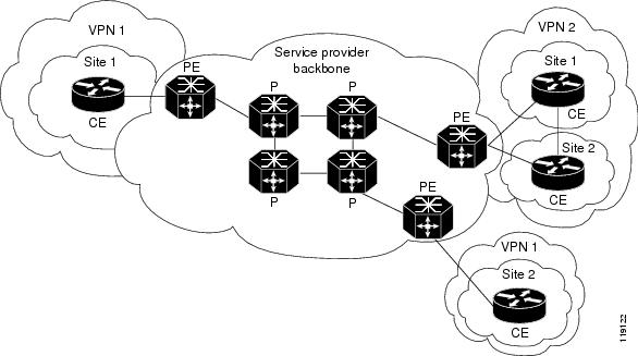
At the ingress PE, the PFC makes a forwarding decision based on the packet headers. The PFC contains a table that maps VLANs to VPNs. In the Cisco 7600 series router architecture, all physical ingress interfaces in the system are associated with a specific VPN. The PFC looks up the IP destination address in the CEF table but only against prefixes that are in the specific VPN. (The table entry points to a specific set of adjacencies and one is chosen as part of the load-balancing decision if multiple parallel paths exist.)
The table entry contains the information on the Layer 2 header that the packet needs, as well as the specific MPLS labels to be pushed onto the frame. The information to rewrite the packet goes back to the ingress line card where it is rewritten and forwarded to the egress line interface.
VPN traffic is handled at the egress from the PE based upon the per-prefix labels or aggregate labels. If per-prefix labels are used, then each VPN prefix has a unique label association; this allows the PE to forward the packet to the final destination based upon a label lookup in the FIB.
Note![]() The PFC allocates only one aggregate label per VRF.
The PFC allocates only one aggregate label per VRF.
If aggregate labels are used for disposition in an egress PE, many prefixes on the multiple interfaces may be associated with the label. In this case, the PFC must perform an IP lookup to determine the final destination. The IP lookup may require recirculation.
MPLS VPN Guidelines and Restrictions
When configuring MPLS VPN, follow these guidelines and restrictions:
MPLS VPN Supported Commands
The PFC supports these MPLS VPN commands:
- address-family
- exit-address-family
- import map
- ip route vrf
- ip route forwarding
- ip vrf
- neighbor activate
- rd
- route-target
For information about these commands, see these publications:
http://www.cisco.com/en/US/docs/ios/12_2/switch/command/reference/fswtch_r.html
Configuring MPLS VPN
For information on configuring MPLS VPN, refer to the MPLS Virtual Private Networks feature module at this URL:
http://www.cisco.com/en/US/docs/ios/12_0st/12_0st21/feature/guide/fs_vpn.html
Note![]() If you use a Layer 3 VLAN interface as the MPLS uplink through a Layer 2 port peering with another MPLS device, then you can use another Layer 3 VLAN interface as the VRF interface.
If you use a Layer 3 VLAN interface as the MPLS uplink through a Layer 2 port peering with another MPLS device, then you can use another Layer 3 VLAN interface as the VRF interface.
MPLS VPN Sample Configuration
This sample configuration shows LAN, OSM, and Enhanced FlexWAN CE-facing interfaces. The PFC MPLS switching configuration is identical to configuration on other platforms.
Any Transport over MPLS
Any Transport over MPLS (AToM) transports Layer 2 packets over an MPLS backbone. AToM uses a directed Label Distribution Protocol (LDP) session between edge routers for setting up and maintaining connections. Forwarding occurs through the use of two level labels that provide switching between the edge routers. The external label (tunnel label) routes the packet over the MPLS backbone to the egress PE at the ingress PE. The VC label is a demuxing label that determines the connection at the tunnel endpoint (the particular egress interface on the egress PE as well as the VLAN identifier for an Ethernet frame).
AToM supports the following like-to-like transport types on the PFC:
- Ethernet over MPLS (EoMPLS) (VLAN mode and port mode)
- Frame Relay over MPLS with DLCI-to-DLCI connections
- ATM AAL5 over MPLS
- ATM Cell Relay over MPLS
Note![]() Additional AToM types are planned in future releases.
Additional AToM types are planned in future releases.
The PFC supports hardware-based EoMPLS and OSM- or Enhanced FlexWAN-based EoMPLS. (Note that Release 12.2SR does not support FlexWAN-based EoMPLS). For more information, see:
http://www.cisco.com/en/US/docs/general/TD_Trash/lczaplys_trash/mpls.html#wp1128955
http://www.cisco.com/en/US/docs/general/TD_Trash/lczaplys_trash/mpls.html#wp1279824
For information on other AToM implementations (ATM AAL5 over MPLS, ATM Cell Relay over MPLS, Frame Relay over MPLS), see this publication:
- AToM Load Balancing
- Understanding EoMPLS
- EoMPLS Guidelines and Restrictions
- Configuring EoMPLS
- Configuring 7600-MUX-UNI Support on LAN Cards
AToM Load Balancing
EoMPLS on the PFC does not support load balancing at the tunnel ingress; only one Interior Gateway Protocol (IGP) path is selected even if multiple IGP paths are available, but load balancing is available at the MPLS core.
Understanding EoMPLS
EoMPLS is one of the AToM transport types. AToM transports Layer 2 packets over a MPLS backbone using a directed LDP session between edge routers for setting up and maintaining connections. Forwarding occurs through the use of two level labels that provide switching between the edge routers. The external label (tunnel label) routes the packet over the MPLS backbone to the egress PE at the ingress PE. The VC label is a demuxing label that determines the connection at the tunnel endpoint (the particular egress interface on the egress PE as well as the VLAN identifier for an Ethernet frame).
EoMPLS works by encapsulating Ethernet PDUs in MPLS packets and forwarding them across the MPLS network. Each PDU is transported as a single packet.
Note![]() Use OSM-based or Enhanced FlexWAN-based EoMPLS when you want local Layer 2 switching and EoMPLS on the same VLAN. You must configure EoMPLS on the SVI, and the core-facing card must be an OSM or an Enhanced FlexWAN module. When local Layer 2 switching is not required, use PFC-based EoMPLS configured on the subinterface or physical interface.
Use OSM-based or Enhanced FlexWAN-based EoMPLS when you want local Layer 2 switching and EoMPLS on the same VLAN. You must configure EoMPLS on the SVI, and the core-facing card must be an OSM or an Enhanced FlexWAN module. When local Layer 2 switching is not required, use PFC-based EoMPLS configured on the subinterface or physical interface.
EoMPLS Guidelines and Restrictions
When configuring EoMPLS, consider these guidelines and restrictions:
- Ensure that the maximum transmission unit (MTU) of all intermediate links between endpoints is sufficient to carry the largest Layer 2 packet received.
- EoMPLS supports VLAN packets that conform to the IEEE 802.1Q standard. The 802.1Q specification establishes a standard method for inserting VLAN membership information into Ethernet frames.
- For VLAN-based EoMPLS, the MTU size on the VLAN subinterface must be greater than 1500 (the default) if a larger MTU size is specified on the physical interface.
Note![]() Port-channel and xconnect combinations are supported on Port-based EoMPLS. However, all the restrictions for normal PFC based EoMPLS are applicable to port-channel and xconnect as well.
Port-channel and xconnect combinations are supported on Port-based EoMPLS. However, all the restrictions for normal PFC based EoMPLS are applicable to port-channel and xconnect as well.
- If QoS is disabled globally, both the 802.1p and IP precedence bits are preserved. When the QoS is enabled on a Layer 2 port, either 802.1q P bits or IP precedence bits can be preserved with the trusted configuration. However, by default the unpreserved bits are overwritten by the value of preserved bits. For instance, if you preserve the P bits, the IP precedence bits are overwritten with the value of the P bits. A new command allows you to configure the PFC to trust the P bits while preserving the IP precedence bits. To preserve the IP precedence bits, use the no mls qos rewrite ip dscp command.
Note![]() The no mls qos rewrite ip dscp command is not compatible with the MPLS and MPLS VPN features. See Chapter48, “Configuring PFC QoS”
The no mls qos rewrite ip dscp command is not compatible with the MPLS and MPLS VPN features. See Chapter48, “Configuring PFC QoS”
Note![]() Do not use the no mls qos rewrite ip dscp command if you have PFC-based EoMPLS and PXF-based EoMPLS services in the same system.
Do not use the no mls qos rewrite ip dscp command if you have PFC-based EoMPLS and PXF-based EoMPLS services in the same system.
- EoMPLS is not supported with private VLANs.
- The following restrictions apply to using trunks with EoMPLS:
–![]() To support Ethernet spanning tree bridge protocol data units (BPDUs) across an EoMPLS cloud, you must disable the supervisor engine spanning tree for the Ethernet-over-MPLS VLAN. This ensures that the EoMPLS VLANs are carried only on the trunk to the customer router. Otherwise, the BPDUs are directed to the supervisor engine and not to the EoMPLS cloud.
To support Ethernet spanning tree bridge protocol data units (BPDUs) across an EoMPLS cloud, you must disable the supervisor engine spanning tree for the Ethernet-over-MPLS VLAN. This ensures that the EoMPLS VLANs are carried only on the trunk to the customer router. Otherwise, the BPDUs are directed to the supervisor engine and not to the EoMPLS cloud.
–![]() The native VLAN of a trunk must not be configured as an EoMPLS VLAN. For more information on Scalable EoMPLS ( SVI-based EoMPLS) and Port-mode EoMPLS and its sample configuration, see Scalable EoMPLS and Port-mode EoMPLS and Sample Configuration for SwEoMPLS and VPLS.
The native VLAN of a trunk must not be configured as an EoMPLS VLAN. For more information on Scalable EoMPLS ( SVI-based EoMPLS) and Port-mode EoMPLS and its sample configuration, see Scalable EoMPLS and Port-mode EoMPLS and Sample Configuration for SwEoMPLS and VPLS.
–![]() PFC-based EoMPLS, also known as Hardware-based EoMPLS where the Earl imposes on the Supervisor or DFC based line card
PFC-based EoMPLS, also known as Hardware-based EoMPLS where the Earl imposes on the Supervisor or DFC based line card
–![]() LAN-based EoMPLS, also known as Software-based EoMPLS, where Earl imposes on the MPLS Core-facing line card
LAN-based EoMPLS, also known as Software-based EoMPLS, where Earl imposes on the MPLS Core-facing line card
–![]() Scalable EoMPLS, where the Earl imposes on customer device facing line card. The feature is supported in the SIP400, ES20, and ES40 as customer-facing line cards. Further, in ES20 and ES40 the solution is supported only in EVC-based configuration.
Scalable EoMPLS, where the Earl imposes on customer device facing line card. The feature is supported in the SIP400, ES20, and ES40 as customer-facing line cards. Further, in ES20 and ES40 the solution is supported only in EVC-based configuration.
- On the PFC, all protocols (for example, CDP, VTP, BPDUs) are tunneled across the MPLS cloud without conditions.
- ISL encapsulation is not supported for the interface that receives EoMPLS packets.
- Unique VLANs are required across interfaces. You cannot use the same VLAN ID on different interfaces.
- EoMPLS tunnel destination route in the routing table and the CEF table must be a /32 address (host address where the mask is 255.255.255.255) to ensure that there is a label-switched path (LSP) from PE to PE.
- For a particular EoMPLS connection, both the ingress EoMPLS interface on the ingress PE and the egress EoMPLS interface on the egress PE have to be subinterfaces with dot1Q encapsulation or neither is a subinterface.
- 802.1Q in 802.1Q over EoMPLS is supported if the outgoing interface connecting to MPLS network is a port on an Layer 2 card.
- Shaping EoMPLS traffic is not supported if the egress interface connecting to an MPLS network is a Layer 2 LAN port (a mode known as PFC-based EoMPLS).
- EoMPLS based on a PFC does not perform any Layer 2 lookup to determine if the destination MAC address resides on the local or remote segment and does not perform any Layer 2 address learning (as traditional LAN bridging does). This functionality (local switching) is available only when using OSM and FlexWAN modules as uplinks.
- In previous releases of AToM, the command used to configure AToM circuits was mpls l2 transport route. This command has been replaced with the xconnect command. You can use the xconnect command to configure EoMPLS circuits.
- The AToM control word is not supported.
- EoMPLS is not supported on Layer 3 VLAN interfaces.
- Point-to-point EoMPLS works with a physical interface and subinterfaces.
- Some of the SPA-based Ethernet line cards like the ES20 support matching the outer VLAN for QinQ traffic. See the documentation for the line card you are interested in for more information.
Scalable EoMPLS and Port-mode EoMPLS
In a scalable EoMPLS scenario, you can configure cross-connect directly on the EVC on the PE routers. In a port-mode EoMPLS, you can configure a cross-connect on the physical interface or subinterface. In case of scalable and port-mode EoMPLS, it is not required to disable spanning tree, since the access facing interfaces do not participate in spanning tree protocol (STP). For more information on configuring the Spanning Tree Protocol (STP) and Multiple Spanning Tree (MST) protocol on Cisco 7600 series routers, refer Chapter 20, “Configuring STP and MST”.
Note![]() Cisco 7600 series routers do not support multiple backup PWs.
Cisco 7600 series routers do not support multiple backup PWs.
HSPW Support for Ethernet ACs
Effective from Cisco IOS Release 15.1(01)S, the Hot-Standby Pseudowire (HSPW) feature is supported on ES+ Line Card and SIP400 PW having imposition and disposition on the access side for ScEoMPLS, ATM and TDM cross connect. Hot-Standby capability helps to improve the switchover time for PW in the service providers network. This feature keeps the backup PW pre-programmed in the hardware. And at switchover, the backup PW is enabled to pass the traffic.
The next section describes sample configurations and scenarios to handle STP and allow the BPDUs to relay through the pseudowire.
Sample Configuration for SwEoMPLS and VPLS
Also termed as SVI-based EoMPLS, the following example outlines a sample topology for SwEoMPLS:
CE1-----PE1-----P------PE2----CE2
In a SwEoMPLS, you configure cross-connect on a SVI interface (interface VLAN). The following is a sample configuration on the CE facing interface:
switchport trunk encapsulation dot1q
switchport trunk allowed vlan 110
The following is a sample configuration for the SVI interface with cross-connect.
xconnect 6.6.6.6 200 encapsulation mpls
Following sample shows a configuration on a core facing line card towards a P router:
interface GigabitEthernet2/2/0
ip address 53.53.53.1 255.255.255.0
Following sample shows a configuration on a CE facing line card for VPLS:
switchport switchport trunk encapsulation dot1q
switchport trunk allowed vlan 110
Following sample shows a configuration when a cross-connect is configured within SVI:
Based on the previous sample configurations, the VFI definitions are defined:
neighbor 6.6.6.6 encapsulation mpls
Following sample shows a configuration on a CE facing line card for VFI:
interface GigabitEthernet2/2/0
Managing Spanning Tree Protocol to allow Bridge Protocol Data Units
The Customer facing interfaces on the PE routers participate in the STP. To support Ethernet spanning tree bridge protocol data units (BPDUs) across an EoMPLS cloud (PE1-P-PE2), modify the methods listed below to disable the supervisor engine spanning tree:
1.![]() If spanning tree mode is MST, then STP BPDUs are untagged.
If spanning tree mode is MST, then STP BPDUs are untagged.
On the CE facing interface on a PE router:
switchport trunk allowed vlan 110
Configure a VFI (mst-1 here) to relay the STP BPDUs.
Attach the VFI configured in the previous step to SVI.
2.![]() If spanning tree mode is PVST, STP BPDUs are tagged. For example, if the customer router’s traffic is expected on VLAN110, then the BPDU's are tagged with VLAN 110.
If spanning tree mode is PVST, STP BPDUs are tagged. For example, if the customer router’s traffic is expected on VLAN110, then the BPDU's are tagged with VLAN 110.
On the access facing interface:
switchport trunk allowed vlan 110
In the above scenario, no spanning-tree vlan 110 is sufficient and a special VFI is not needed to relay BPDUs.
Configuring EoMPLS
Prerequisites
Before you configure EoMPLS, ensure that the network is configured as follows:
- Configure IP routing in the core so that the PE routers can reach each other through IP.
- Configure MPLS in the core so that a label switched path (LSP) exists between the PE routers.
EoMPLS works by encapsulating Ethernet PDUs in MPLS packets and forwarding them across the MPLS network. Each PDU is transported as a single packet. Two methods are available to configure EoMPLS on the PFC:
- VLAN mode—Transports Ethernet traffic from a source 802.1Q VLAN to a destination 802.1Q VLAN through a single VC over an MPLS network. VLAN mode uses VC type 5 as default (no dot1q tag) and VC type 4 (transport dot1 tag) if the remote PE does not support VC type 5 for subinterface (VLAN) based EoMPLS.
- Port mode—Allows all traffic on a port to share a single VC across an MPLS network. Port mode uses VC type 5.
Note ●![]() For both VLAN mode and port mode, EoMPLS on the PFC does not allow local switching of packets between interfaces unless you use loopback ports.
For both VLAN mode and port mode, EoMPLS on the PFC does not allow local switching of packets between interfaces unless you use loopback ports.
- A system can have both an OSM or Enhanced FlexWAN configuration and PFC-mode configuration enabled at the same time. Cisco supports this configuration but does not recommend it.
- Unless the uplinks to the MPLS core are through OSM or Enhanced FlexWAN-enabled interfaces, OSM or Enhanced FlexWAN-based EoMPLS connections will not be active; this causes packets for OSM or Enhanced FlexWAN-based EoMPLS arriving on non-WAN interfaces to be dropped.
The PFC supports MPLS. With a PFC, LAN ports can receive Layer 2 traffic, impose labels, and switch the frames into the MPLS core without using an OSM or Enhanced FlexWAN module.
With a PFC, you can configure an OSM or an Enhanced FlexWAN module to face the core of MPLS network and use either the OSM configuration, the Enhanced FlexWAN configuration, or the PFC-mode configuration.
For more information on EoMPLS over WAN (Enhanced FlexWAN and OSM), see the following publication. (Note that Release 12.2SR does not support FlexWAN-based EoMPLS).
http://www.cisco.com/en/US/docs/general/TD_Trash/lczaplys_trash/mpls.html#wp1128955
Configuring PFC-Mode VLAN-Based EoMPLS
When configuring VLAN-based EoMPLS on the PFC, follow these guidelines and restrictions:
- The AToM control word is not supported.
- Ethernet packets with hardware-level cyclic redundancy check (CRC) errors, framing errors, and runt packets are discarded on input.
- You must configure VLAN-based EoMPLS on subinterfaces. In addition, the MTU size on the VLAN subinterface must be greater than 1500 (the default) if a larger MTU size is specified on the physical interface.
To configure VLAN-based EoMPLS on the PFC, perform this task on the provider edge (PE) routers.
Here is a sample of a VLAN-based EoMPLS configuration on the PFC:
Note![]() The IP address is configured on subinterfaces of the CE devices.
The IP address is configured on subinterfaces of the CE devices.
Verifying the Configuration
To verify and display the configuration of Layer 2 VLAN transport over MPLS tunnels, perform the following:
- To display a single line for each VLAN, naming the VLAN, status, and ports, enter the show vlan brief command.
- To make sure that the PE router endpoints have discovered each other, enter the show mpls ldp discovery command. When an PE router receives an LDP Hello message from another PE router, it considers that router and the specified label space to be “discovered.”
- To make sure that the label distribution session has been established, enter the show mpls ldp neighbor command. The third line of the output shows that the state of the LDP session is operational and shows that messages are being sent and received.
- To ensure that the label forwarding table is built correctly, enter the show mpls forwarding-table command to verify that a label has been learned for the remote PE and that the label is going from the correct interface to the correct next-hop.
The output shows the following data:
–![]() Local tag—Label assigned by this router.
Local tag—Label assigned by this router.
–![]() Outgoing tag or VC—Label assigned by next hop.
Outgoing tag or VC—Label assigned by next hop.
–![]() Prefix or Tunnel Id—Address or tunnel to which packets with this label are going.
Prefix or Tunnel Id—Address or tunnel to which packets with this label are going.
–![]() Bytes tag switched— Number of bytes switched out with this incoming label.
Bytes tag switched— Number of bytes switched out with this incoming label.
–![]() Outgoing interface—Interface through which packets with this label are sent.
Outgoing interface—Interface through which packets with this label are sent.
–![]() Next Hop—IP address of neighbor that assigned the outgoing label.
Next Hop—IP address of neighbor that assigned the outgoing label.
To see detailed information about each VC, add the keyword detail.
Configuring Port-Based EoMPLS on the PFC
When configuring port-based EoMPLS on the PFC, follow these guidelines and restrictions:
- The AToM control word is not supported.
- Ethernet packets with hardware-level cyclic redundancy check (CRC) errors, framing errors, and runt packets are discarded on input.
- Port-based EoMPLS and VLAN-based EoMPLS are mutually exclusive. If you enable a main interface for port-to-port transport, you also cannot enter commands on a subinterface.
To support 802.1Q-in-802.1Q traffic and Ethernet traffic over EoMPLS on the PFC, configure port-based EoMPLS by performing this task:
The following is an example of a port-based configuration:
Verifying the Configuration
To verify and display the configuration of Layer 2 VLAN transport over MPLS tunnels, perform the following:
- To display a single line for each VLAN, naming the VLAN, status, and ports, enter the show vlan brief command.
- To make sure the PE router endpoints have discovered each other, enter the show mpls ldp discovery command. When an PE router receives an LDP Hello message from another PE router, it considers that router and the specified label space to be “discovered.”
- To make sure the label distribution session has been established, enter the show mpls ldp neighbor command. The third line of the output shows that the state of the LDP session is operational and shows that messages are being sent and received.
- To make sure the label forwarding table is built correctly, enter the show mpls forwarding-table command.
–![]() Local tag—Label assigned by this router.
Local tag—Label assigned by this router.
–![]() Outgoing tag or VC—Label assigned by next hop.
Outgoing tag or VC—Label assigned by next hop.
–![]() Prefix or Tunnel Id—Address or tunnel to which packets with this label are going.
Prefix or Tunnel Id—Address or tunnel to which packets with this label are going.
–![]() Bytes tag switched— Number of bytes switched out with this incoming label.
Bytes tag switched— Number of bytes switched out with this incoming label.
–![]() Outgoing interface—Interface through which packets with this label are sent.
Outgoing interface—Interface through which packets with this label are sent.
–![]() Next Hop—IP address of neighbor that assigned the outgoing label.
Next Hop—IP address of neighbor that assigned the outgoing label.
Configuring 7600-MUX-UNI Support on LAN Cards
A User Network Interface (UNI) is the point where the customer edge (CE) eqipment connects to the ingress PE and an attachment VLAN is a VLAN on a UNI port.
The 7600-MUX-UNI Support on LAN Cards feature provides the ability to partition a physical port on an attachment VLAN to provide multiple Layer 2 and Layer 3 services over a single UNI.
When configuring 7600-MUX-UNI Support on LAN Cards, follow these guidelines and restrictions:
- Encapsulation on main interface has to be dot1Q and not ISL
- With dot1q encapsulation on the main interface, you cannot configure ISL on the subinterfaces; Layer 3 interfaces are unaffected
To configure 7600-MUX-UNI Support on LAN Cards, perform this task on the provider edge (PE) routers.
This example for the 7600-MUX-UNI Support on LAN Cards feature shows a physical trunk port used as UNI:
This example for the 7600-MUX-UNI Support on LAN Cards feature shows a Layer 2 port channel used as UNI:
This example for the 7600-MUX-UNI Support on LAN Cards feature shows Layer 3 termination and VRF for Muxed UNI ports:
 Feedback