Feedback
Table Of Contents
Configuring Multiprotocol Label Switching on the Optical Services Modules
MPLS Limitations and Restrictions
Understanding the MPLS Experimental Field
Configuring Class-Based Marking for MPLS (Supervisor Engine 2)
Configuring a Class Map to Classify MPLS Packets
Configuring a Policy Map to Set the MPLS Experimental Field
Ingress PE Router Configuration
MPLS VPN Limitations and Restrictions
MPLS VPN Memory Requirements and Recommendations
Restrictions for Any Transport over MPLS
Ethernet over MPLS Restrictions
ATM AAL5 over MPLS Restrictions
ATM Cell Relay over MPLS Restrictions
Frame Relay over MPLS Restrictions
Information About Any Transport over MPLS
How AToM Transports Layer 2 Packets
Compatibility with Previous Releases of AToM
Supervisor Engine 2-Based EoMPLS
Configuring EoMPLS VLAN Mode for Supervisor Engine 2 or OSM-Based System
Configuring EoMPLS VLAN Mode for SUP720-3BXL-Based System
Ethernet over MPLS VLAN Mode Configuration Guidelines
Configuring EoMPLS Port Mode for Supervisor Engine 2 or OSM-Based System
Configuring EoMPLS Port Mode for SUP720-3BXL-Based System
Ethernet over MPLS Port Mode Configuration Guidelines
Configuring ATM AAL5 over MPLS VC-Mode
ATM Cell Relay over MPLS VC-Mode
Configuring ATM Cell Relay over MPLS VC-Mode
Configuring Frame Relay over MPLS with DLCI-to-DLCI Connections
Layer 2 Local Switching-ATM to ATM
Configuring ATM VC to VC Local Switching with AAL5 Encapsulation
Configuring ATM VC to VC Local Switching with AAL0 Encapsulation
Configuring ATM VP to VP Local Switching with AAL0 Encapsulation
Configuring Frame Relay DLCI Local Switching
Enabling Other PE Devices to Transport Frame Relay Packets
Local Management Interface and Frame Relay over MPLS
DE/CLP and EXP Mapping on FR/ATMoMPLS VC
Restrictions for Match on ATM CLP Bit
Configuring Match on ATM CLP Bit for Ingress Policy
Restrictions for Match on FR-DE Bit
Configuring Match on FR-DE Bit for Ingress Policy
Restrictions for Set on ATM CLP Bit
Configuring Set on ATM CLP Bit for Egress Policy
Configuring Set on FR-DE for Egress Policy
How to Configure QoS with AToM
How to Set Experimental Bits with AToM
Ethernet over MPLS and EXP Bits
ATM AAL5 over MPLS and EXP Bits
ATM Cell Relay over MPLS and EXP Bits
Frame Relay over MPLS and EXP Bits
Setting the Priority of Packets with EXP Bits
EoMPLS QoS Example—Displaying the Traffic Policy Assigned to an Interface
EoMPLS QoS Example— Configuring QoS on VLAN
ATMoMPLS QoS Example—Configuring Ingress QoS
FRoMPLS QoS Example —Configuring Ingress QoS
HQoS for EoMPLS Virtual Circuits
Prerequisites for the HQoS for EoMPLS VCs Feature
Restrictions for the HQoS for EoMPLS VCs Feature
Configuring the HQoS for EoMPLS VCs Feature
Creating and Assigning a Policy Map to Mark the QoS Group at the Incoming Interface
Configuring the Class Map to Match on a QoS Group
Creating the Child Policy Map for the Egress Interface
Configuring the Class Maps for Matching on an Input VLAN
Creating the Parent Policy Map and Attaching It to the Egress Interface
Configuration Examples for the HQoS for EoMPLS VCs Feature
Simple Hierarchical Configuration Example
Complete Hierarchical QoS Example
Multiple Parent Policies Using the Same Child Policy Example
Common Class-Map Templates Example
Virtual Private LAN Services on the Optical Services Modules
Multipoint-to-Multipoint Support
MAC-Address Learning Forwarding and Aging
Q-in-Q Support and Q-in-Q to EoMPLS Support
Ethernet Virtual Connection Service
Configuring the PE Layer 2 Interface to the CE
Configuring Layer 2 VLAN Instance on the PE
Configuring MPLS WAN Interface on the PE
Associating the Attachment Circuit with the VSI at the PE
Full-Mesh Configuration Example
H-VPLS with MPLS Edge Configuration Example
Traffic Engineering for Transport Tunnel
Configuring Dot1q Transparency for EoMPLS
Configuring Multiprotocol Label Switching on the Optical Services Modules
This chapter describes how to configure Multiprotocol Label Switching (MPLS) and Any Transport over Multiprotocol Label Switching (AToM) on the Optical Services Modules (OSMs).
This chapter consists of these sections:
•
ATM Cell Relay over MPLS VC-Mode
•
•
•
Configuring MPLS
These sections describe MPLS and provides configuration information:
•
Understanding MPLS
MPLS uses label switching to forward packets over various link-level technologies such as Packet-over-SONET, Frame Relay, ATM, and Ethernet. Labels are assigned to packets based on groupings or forwarding equivalence classes (FECs). Packets belonging to the same FEC get similar treatment. The label is added between the Layer 2 and the Layer 3 header (in a packet environment) or in the virtual path identifier/virtual channel identifier (VPI/VCI) field (in ATM networks).
In an MPLS network, the edge router performs a label lookup of the incoming label, swaps the incoming label with an outgoing label, and sends the packet to the next hop. Labels are imposed on packets only at the ingress edge of the MPLS network and are removed at the egress edge. The core network reads the labels, applies the appropriate services, and forwards the packets based on the labels.
MPLS Support on OSMs
MPLS is supported on the following Catalyst 6000 family and Cisco 7600 series OSMs:
•
–
–
–
–
–
•
–
–
–
–
•
–
–
–
–
•
–
–
•
–
–
–
–
Note
•
–
Note
•
–
–
•
•
Supported Features
The following features are supported with the SUP720-3BXL and the supervisor engine 2:
Note
•
Note
Note
•
•
•
•
For information on forwarding adjacency with Open Shortest Path First (OSPF) routing, see http://www.cisco.com/univercd/cc/td/doc/product/software/ios120/120newft/120limit/120s/120s24/ospffa.htm.
•
•
•
•
•
•
•
•
•
•
MPLS Limitations and Restrictions
The following platform-specific limitations and restrictions apply to the MPLS support on the OSM modules:
•
MPLS Limitations
The following MPLS limitations apply:
•
•
•
•
Note
Configuring MPLS
For information on configuring MPLS, refer to the Multiprotocol Label Switching on Cisco Routers feature module at the following URLs:
http://www.cisco.com/univercd/cc/td/doc/product/software/ios121/121newft/121t/121t5/mpls4t.htm
HDLC Over MPLS
HDLC over MPLS encapsulates HDLC protocol data units (PDUs) in MPLS packets and forwards them across the MPLS network. The PE routers do not participate in any protocol negotiation or authentication.
HDLC Over MPLS Restrictions
The following restrictions pertain to the HDLC over MPLS feature:
•
•
Note
Supported OSMs
The following OSMs support HDLC over MPLS:
•
–
–
•
–
–
•
–
Note
–
Configuring HDLC Over MPLS
With HDLC over MPLS, the whole HDLC packet is transported. The ingress PE router removes only the HDLC flags and frame check sequence (FCS) bits. The contents of the packet are not used or changed.
SUMMARY STEPS
1.
2.
3.
4.
5.
DETAILED STEPS
This example shows an HDLC over MPLS configuration and verification:
PE1# show run int pos1/8Building configuration...Current configuration : 137 bytes!interface POS1/8mtu 5000no ip addressmls qos trust dscpclock source internalxconnect 33.33.33.33 101 encapsulation mplsendPE1# sh mpls l2 vc 101Local intf Local circuit Dest address VC ID Status------------- -------------------- --------------- ---------- ----------PO1/8 HDLC 33.33.33.33 101 UPPE1#PE1# sh mpls l2 vc 101 detailLocal interface: PO1/8 up, line protocol up, HDLC upDestination address: 33.33.33.33, VC ID: 101, VC status: upTunnel label: imp-null, next hop point2pointOutput interface: PO4/4.1, imposed label stack {1396}Create time: 00:17:49, last status change time: 00:03:33Signaling protocol: LDP, peer 33.33.33.33:0 upMPLS VC labels: local 25, remote 1396Group ID: local 0, remote 0MTU: local 5000, remote 5000Remote interface description:Sequencing: receive disabled, send disabledVC statistics:packet totals: receive 1011, send 1010byte totals: receive 104898, send 104562packet drops: receive 0, send 0PE1# sh mpls for | inc PO1/825 Untagged l2ckt(101) 114705 PO1/8 point2pointPE1#PE2#sh run int pos8/1Building configuration...Current configuration : 137 bytes!interface POS8/1mtu 5000no ip addressmls qos trust dscpclock source internalxconnect 11.11.11.11 101 encapsulation mplsendPE2# sh mpls l2 vc 101Local intf Local circuit Dest address VC ID Status------------- -------------------- --------------- ---------- ----------PO8/1 HDLC 11.11.11.11 101 UPPE2#sh mpls l2 vc 101 detailLocal interface: PO8/1 up, line protocol up, HDLC upDestination address: 11.11.11.11, VC ID: 101, VC status: upTunnel label: imp-null, next hop point2pointOutput interface: PO8/4.1, imposed label stack {25}Create time: 00:12:37, last status change time: 00:06:19Signaling protocol: LDP, peer 11.11.11.11:0 upMPLS VC labels: local 1396, remote 25Group ID: local 0, remote 0MTU: local 5000, remote 5000Remote interface description:Sequencing: receive disabled, send disabledVC statistics:packet totals: receive 1028, send 1028byte totals: receive 105960, send 105940packet drops: receive 0, send 0PE2# sh mpls for | inc PO8/11396 Untagged l2ckt(101) 114634 PO8/1 point2pointPE2#CE1#sh run int pos3/0/0Building configuration...Current configuration : 127 bytes!interface POS3/0/0ip address 130.0.0.1 255.0.0.0no ip directed-broadcastno ip mroute-cacheclock source internalendCE2# sh run int pos3/0Building configuration...Current configuration : 123 bytes!interface POS3/0mtu 5000ip address 130.0.0.2 255.0.0.0no ip directed-broadcastcrc 16clock source internalendCE1# pingProtocol [ip]:Target IP address: 130.0.0.2Repeat count [5]: 1000Datagram size [100]:Timeout in seconds [2]:Extended commands [n]:Sweep range of sizes [n]:Type escape sequence to abort.Sending 1000, 100-byte ICMP Echos to 130.0.0.2, timeout is 2 seconds:!!!!!!!!!!!!!!!!!!!!!!!!!!!!!!!!!!!!!!!!!!!!!!!!!!!!!!!!!!!!!!!!!!!!!!!!!!!!!!!!!!!!!!!!!!!!!!!!!!!!!!!!!!!!!!!!!!!!!!!!!!!!!!!!!!!!!!!!!!!!!!!!!!!!!!!!!!!!!!!!!!!!!!!!!!!!!!!!!!!!!!!!!!!!!!!!!!!!!!!!!!!!!!!!!!!!!!!!!!!!!!!!!!!!!!!!!!!!!!!!!!!!!!!!!!!!!!!!!!!!!!!!!!!!!!!!!!!!!!!!!!!!!!!!!!!!!!!!!!!!!!!!!!!!!!!!!!!!!!!!!!!!!!!!!!!!!!!!!!!!!!!!!!!!!!!!!!!!!!!!!!!!!!!!!!!!!!!!!!!!!!!!!!!!!!!!!!!!!!!!!!!!!!!!!!!!!!!!!!!!!!!!!!!!!!!!!!!!!!!!!!!!!!!!!!!!!!!!!!!!!!!!!!!!!!!!!!!!!!!!!!!!!!!!!!!!!!!!!!!!!!!!!!!!!!!!!!!!!!!!!!!!!!!!!!!!!!!!!!!!!!!!!!!!!!!!!!!!!!!!!!!!!!!!!!!!!!!!!!!!!!!!!!!!!!!!!!!!!!!!!!!!!!!!!!!!!!!!!!!!!!!!!!!!!!!!!!!!!!!!!!!!!!!!!!!!!!!!!!!!!!!!!!!!!!!!!!!!!!!!!!!!!!!!!!!!!!!!!!!!!!!!!!!!!!!!!!!!!!!!!!!!!!!!!!!!!!!!!!!!!!!!!!!!!!!!!!!!!!!!!!!!!!!!!!!!!!!!!!!!!!!!!!!!!!Success rate is 100 percent (1000/1000), round-trip min/avg/max = 1/1/4 ms
Note
PPP Over MPLS
PPP over MPLS encapsulates PPP PDUs in MPLS packets and forwards them across the MPLS network. The PE routers do not participate in any protocol negotiation or authentication.
Note
Supported OSMs
The following OSMs support HDLC over MPLS:
•
–
–
•
–
–
•
–
–
PPP Over MPLS Restrictions
The following restrictions pertain to the PPP over MPLS feature:
•
•
•
Note
Configuring PPP Over MPLS
With PPP over MPLS, the ingress PE router removes the flags, address, control field, and the frame check sequence (FCS).
SUMMARY STEPS
1.
2.
3.
4.
5.
Detailed Steps
This example shows configuration and verification:
PE1# sh run int pos1/8Building configuration...Current configuration : 156 bytes!interface POS1/8mtu 5000no ip addressencapsulation pppmls qos trust dscpclock source internalxconnect 33.33.33.33 101 encapsulation mplsendPE2# sh run int pos8/1Building configuration...Current configuration : 156 bytes!interface POS8/1mtu 5000no ip addressencapsulation pppmls qos trust dscpclock source internalxconnect 11.11.11.11 101 encapsulation mplsendThis example show how to verify the configuration:
PE1#PE1# sh mpls l2 vc 101Local intf Local circuit Dest address VC ID Status------------- -------------------- --------------- ---------- ----------PO1/8 PPP 33.33.33.33 101 UPPE1#PE2# sh mpls l2 vc 101Local intf Local circuit Dest address VC ID Status------------- -------------------- --------------- ---------- ----------PO8/1 PPP 11.11.11.11 101 UPPE2#PE1# sh mpls l2 vc 101 detailLocal interface: PO1/8 up, line protocol up, PPP upDestination address: 33.33.33.33, VC ID: 101, VC status: upTunnel label: imp-null, next hop point2pointOutput interface: PO4/4.1, imposed label stack {2530}Create time: 00:02:02, last status change time: 00:01:16Signaling protocol: LDP, peer 33.33.33.33:0 upMPLS VC labels: local 413, remote 2530Group ID: local 0, remote 0MTU: local 5000, remote 5000Remote interface description:Sequencing: receive disabled, send disabledVC statistics:packet totals: receive 19, send 18byte totals: receive 1394, send 1058packet drops: receive 0, send 0PE2# sh mpls l2 vc 101 detailLocal interface: PO8/1 up, line protocol up, PPP upDestination address: 11.11.11.11, VC ID: 101, VC status: upTunnel label: imp-null, next hop point2pointOutput interface: PO8/4.1, imposed label stack {413}Create time: 00:01:49, last status change time: 00:01:15Signaling protocol: LDP, peer 11.11.11.11:0 upMPLS VC labels: local 2530, remote 413Group ID: local 0, remote 0MTU: local 5000, remote 5000Remote interface description:Sequencing: receive disabled, send disabledVC statistics:packet totals: receive 19, send 19byte totals: receive 1074, send 1069packet drops: receive 0, send 0
Note
Configuring MPLS QoS
These sections provide configuration information for MPLS QoS:
•
•
Supported MPLS QoS Features
The OSMs support the following MPLS QoS features:
•
•
•
Note
Understanding the MPLS Experimental Field
Setting the MPLS experimental field value satisfies the requirement of service providers that do not want the value of the IP precedence field modified within IP packets transported through their networks.
By choosing different values for the MPLS experimental field, you can mark packets so that packets have the priority that they require during periods of congestion.
By default, the IP precedence value is copied into the MPLS experimental field during imposition.You can mark the MPLS EXP bits with a PFC3BXL policy.
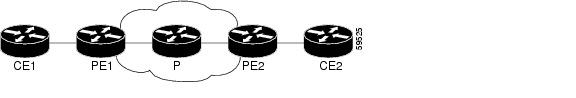
Figure 11-1 shows a service provider's MPLS network that connects two sites of a customer's network.
Figure 11-1 MPLS Network Connecting Two Sites of a Customer's IP Network
Configuring Class-Based Marking for MPLS (Supervisor Engine 2)
To configure Class-based Marking for MPLS (Supervisor Engine 2), perform the tasks described in the following sections:
•
•
Note
Configuring a Class Map to Classify MPLS Packets
To configure a class map, perform this task beginning in global configuration mode:
This example shows that all packets that contain MPLS experimental value 4 are matched by the traffic class exp4:
Router(config)# class-map exp4
Router(config-cmap)# match mpls experimental 4
Router(config-cmap)# exit
Configuring a Policy Map to Set the MPLS Experimental Field
To configure a policy map, perform this task beginning in global configuration mode:
Step 1
Creates a policy map that can be attached to one or more interfaces to specify a service policy.
Step 2
Specifies the name of the class map previously designated in the class-map command.
Step 3
Designates the value to which the MPLS bits are set if the packets match the specified policy map.
Step 4
Exits policy-map configuration mode.
1 You can also configure additional supported features, such as shaping.
This example shows that the value in the MPLS experimental field of each packet that is matched by the class-map exp4 is set to 5:
Router(config)# policy-map set_experimental_5
Router(config-pmap)# class exp4
Router(config-pmap-c)# set mpls experimental 5
Router(config-pmap-c)# exit
Router(config-pmap)# exitAttaching the Service Policy
To attach the service policy to an interface, perform this task beginning in global configuration mode:
This example shows that the service policy set_experimental_5 is attached to an POS output interface:
Router(config)# interface POS6/1
Router(config-if)# service-policy output set_experimental_5
Router(config-if)# exit
Verifying QoS Operation
To verify the operation of MPLS QoS, perform this task:
Router# show policy-map interface [interface-name]
Displays detailed information about QoS.
Configuration Examples
Sample configurations provided in this section can be applied to either OSMs or FlexWAN modules supported on the Cisco 7600 series routers.
Ingress PE Router Configuration
In the following example, IP packets with IP precedence 1 entering an MPLS network are shaped to 2000000 bits per second and set to MPLS experimental field 5. When IP packets with IP precedence 0 enter the MPLS network, they are shaped to 3000000 bits per second and set to MPLS experimental field 3. When IP packets with any other IP precedence value enter the MPLS network, they are shaped to 5000000 bits per second.
Step 1
Router(config)# class-map goldRouter(config-cmap)# match mpls experimental 1Router(config-cmap)# exitRouter(config)# class-map silverRouter(config-cmap)# match mpls experimental 0Router(config-cmap)# exit
Note
Step 2
Router(config)# policy-map policy1Router(config-pmap)# class goldRouter(config-pmap-c)# set mpls experimental 5Router(config-pmap-c)# shape average 2000000Router(config-pmap-c)# exitRouter(config-pmap)# class silverRouter(config-pmap-c)# set mpls experimental 3Router(config-pmap-c)# shape average 3000000Router(config-pmap-c)# exitRouter(config-pmap)# class class-defaultRouter(config-pmap-c)# shape average 5000000Router(config-pmap-c)# exitRouter(config-pmap)# exitStep 3
Router(config)# interface GE-WAN7/1Router(config-if)# service-policy output policy1Step 4
Router# show policy-map interface POS6/2POS6/2service-policy output:policy1class-map:gold (match-all)0 packets, 0 bytes30 second offered rate 0 bps, drop rate 0 bpsmatch:mpls experimental 1queue size 0, queue limit 500packets output 0, packet drops 0tail/random drops 0, no buffer drops 0, other drops 0set:mpls experimental 5shape:cir 2000000, Bc 8000, Be 8000output bytes 0, shape rate 0 bpsclass-map:silver (match-all)9521 packets, 9425790 bytes30 second offered rate 3681000 bps, drop rate 1505000 bpsmatch:mpls experimental 0queue size 0, queue limit 128packets output 2845, packet drops 6676tail/random drops 6676, no buffer drops 0, other drops 0set:mpls experimental 3shape:cir 3000000, Bc 12000, Be 12000output bytes 2816550, shape rate 642000 bpsclass-map:class-default (match-any)0 packets, 0 bytes30 second offered rate 0 bps, drop rate 0 bpsmatch:any0 packets, 0 bytes30 second rate 0 bpsqueue size 0, queue limit 128packets output 0, packet drops 0tail/random drops 0, no buffer drops 0, other drops 0shape:cir 5000000, Bc 20000, Be 20000output bytes 0, shape rate 0 bpsRouter#Configuring MPLS VPN
These sections describe how to configure MPLS VPN:
•
•
•
MPLS VPN Support on OSMs
MPLS VPN is supported on the following OSMs:
•
–
–
–
–
–
•
–
–
–
–
•
–
–
–
–
•
–
–
•
–
–
–
•
–
•
–
–
•
•
MPLS VPN Limitations and Restrictions
The following MPLS VPN limitations apply:
•
•
•
•
•
•
•
MPLS VPN Memory Requirements and Recommendations
When a Cisco 7600 series router or a Catalyst 6500 series switch functions as a PE router in an MPLS VPN environment, the memory requirements that are listed in Table 11-1apply:
If the number of Internet routes, eBGP sessions, and VPNv4 routes exceed those listed in Table 11-1, upgrade to the next memory option. If you have a FlexWAN module installed in the system, the number of Internet routes, eBGP sessions, and VPNv4 routes in the configuration file must not exceed the requirement listed in the table for FlexWAN.
MPLS Per-Label Load Balancing
Note
When the Cisco 7600 router is configured as a P router, you can ensure traffic is distributed among equal cost paths by using the mpls load-balance per-label command to enable or disable the load balancing for tag-to-tag traffic.
When enabled, MPLS per-label load balancing ensures that traffic is balanced based on the incoming labels (per prefix) among MPLS interfaces; each interface supports an equal number of incoming labels.
mpls load-balance per-label[no] mpls load-balance per-labelThe default is disabled.
Use the no form of the command to return to the default setting.
This example shows how to enable load balancing for tag-to-tag traffic:
Router(config)# mpls load-balance per-labelRouter(config)#
Note
You can use the show mpls ttfib command to view the incoming label (indicated by an asterisk*) that is included in the load balancer. The following shows the output of the show mpls ttfib command:
Router# show mpls ttfibLocal Outgoing Packets Tag LTL Dest. Destination OutgoingTag Tag or VC Switched Index Vlanid Mac Address Interface4116 21 0 0xE0 1020 0000.0400.0000 PO4/1*34 0 0x132 1019 00d0.040d.380a GE5/345 0 0xE3 4031 0000.0430.0000 PO4/44117 16 0 0x132 1019 00d0.040d.380a GE5/3*17 0 0xE0 1020 0000.0400.0000 PO4/118 0 0xE3 4031 0000.0430.0000 PO4/44118 21 0 0xE0 1020 0000.0400.0000 PO4/1*56 0 0xE3 4031 0000.0430.0000 PO4/44119 35 0 0xE3 4031 0000.0430.0000 PO4/4*47 0 0xE0 1020 0000.0400.0000 PO4/1
Note
For information on configuring MPLS VPN, refer to the MPLS Virtual Private Networks feature module at this URL:
http://www.cisco.com/univercd/cc/td/doc/product/software/ios120/120newft/120t/120t7/vpn_en.htm.
Configuring MPLS VPN QoS
The OSMs support the following MPLS VPN QoS features:
•
•
•
In addition to these features, for Supervisor Engine 2-based systems, MPLS VPN also supports the set ip precedence command on the input WAN interfaces on the OSMs.
The following restrictions apply to the support for MPLS VPN QoS on the OSMs:
•
•
Match IP precedence and SET IP precedence and MPLS Experimental values are supported on the input interface only.
Configuration Example
The following example shows how to configure QoS on an MPLS VPN:
Router# configure terminalRouter(config)# class-map match-any vpn-classRouter(config-cmap)# match ip precedence 3Router(config-cmap)# exitRouter(config)# policy-map VPN-MARKINGRouter(config-pmap)# class vpn-classRouter(config-pmap-c)# set ip precedence 5Router(config-pmap-c)# set mpls exp 5Router(config-pmap-c)# ^ZRouter# configure terminalRouter(config)# interface ge-WAN 5/4Router(config-if)# service-policy input VPN-MARKINGRouter(config-if)# ^ZRouter# show running-config interface g5/4Building configuration...Current configuration :175 bytes!interface GE-WAN5/4ip vrf forwarding TESTip address 194.3.1.3 255.255.255.0negotiation autoservice-policy input VPN-MARKINGmls qos trust dscpendRouter#
Any Transport over MPLS
Any Transport over MPLS (AToM) transports Layer 2 packets over a Multiprotocol Label Switching (MPLS) backbone. AToM uses a directed Label Distribution Protocol (LDP) session between edge routers for setting up and maintaining connections. Forwarding occurs through the use of two level labels, switching between the edge routers. The external label (tunnel label) routes the packet over the MPLS backbone to the egress Provider Edge (PE) at the ingress PE. The VC label is a demuxing label that determines the connection at the tunnel endpoint (the particular egress interface on the egress PE as well as the VPI/VCI value for the AAL5 PDU, the DLCI value for Frame Relay PDU, or the VLAN identifier for an Ethernet frame).
AToM supports the following like-to-like transport types for SUP720-3BXL-based systems and for supervisor engine 2-based systems:
•
Note
•
•
•
Note
Also, the specific MPLS core-facing line card may not be supported for a specific AToM technology; view specific AToM configurations in this chapter, in the FlexWAN and Enhanced FlexWAN Installation and Configuration Note, and in the Cisco 7600 Series Router SIP, SSC, and SPA Software Configuration Guide for more details.
Restrictions for Any Transport over MPLS
The following general restrictions pertain to all transport types under AToM:
•
•
•
•
Ethernet over MPLS Restrictions
The following restrictions pertain to the Ethernet over MPLS feature:
•
•
•
Note
•
•
–
–
•
–
–
•
•
•
•
•
•
•
•
ATM AAL5 over MPLS Restrictions
The following restrictionapplies to the ATM AAL5 over MPLS feature.
•
•
ATM Cell Relay over MPLS Restrictions
The following restrictions pertain to the ATM Cell Relay over MPLS feature:
•
•
Note
•
Note
•
•
•
•
Frame Relay over MPLS Restrictions
The Frame Relay over MPLS feature has the following restriction:
•
•
•
•
•
•
Information About Any Transport over MPLS
To configure AToM, you must understand the following concepts:
•
•
How AToM Transports Layer 2 Packets
AToM encapsulates Layer 2 frames at the ingress PE and sends them to a corresponding PE at the other end of a pseudowire, which is a connection between the two PE routers. The egress PE removes the encapsulation and sends out the Layer 2 frame.
The successful transmission of the Layer 2 frames between PE routers is due to the configuration of the PE routers. You set up the connection, called a pseudowire, between the routers. You specify the following information on each PE router:
•
•
•
The following example shows the basic configuration steps on a PE router that enable the transport of Layer 2 packets. Each transport type (EoMPLS, ATMoMPLS, FRoMPLS) has slightly different steps.
First define the interface or subinterface on the PE router.
Router# interface interface-type interface-numberThen specify the encapsulation type for the interface, such as dot1q.
Router(config-if)# encapsulation encapsulation-typeThe last step does the following:
•
•
The combination of the peer-router-id and the VC ID must be a unique combination on the router. Two circuits cannot use the same combination of peer-router-id and VC ID.
•
Router(config-if)# xconnect peer-router-id vcid encapsulation mpls
Note
Compatibility with Previous Releases of AToM
In previous releases of AToM, the command used to configure AToM circuits was mpls l2 transport route. This command has been replaced with the xconnect command. You can use the xconnect command to configure FRoMPLS and EoMPLS circuits.
Note
Benefits of AToM
The following list explains some of the benefits of enabling Layer 2 packets to be sent in the MPLS network:
•
•
•
Prerequisites
Before configuring AToM, ensure that the network is configured as follows:
•
•
AToM and QoS
MPLS AToM uses the three experimental bits in a label to determine the queue of packets. You statically set the experimental bits in both the VC label and the LSP tunnel label, because the LSP tunnel label might be removed at the penultimate router. See "How to Configure QoS with AToM" section and "HQoS for EoMPLS Virtual Circuits" section for more information.
Ethernet over MPLS
Ethernet over MPLS works by encapsulating Ethernet PDUs in MPLS packets and forwarding them across the MPLS network. Each PDU is transported as a single packet. There are various ways to configure Ethernet over MPLS:
•
•
There are two methods to configure EoMPLS on a SUP720-3BXL-based system and one method for a supervisor engine 2-based system.
SUP720-3BXL-Based EoMPLS
With SUP720-3BXL-based systems the supervisor engine 720 supports the MPLS functionality. The supervisor engine 720 can receive Layer 2 traffic, impose labels, and switch the frames into the MPLS core without using an OSM or FlexWAN module.
You can also equip a SUP720-3BXL-based system with an OSM or a Flexwan module facing the core of MPLS network. In this case, you can use either OSM/FlexWAN-based configuration or the SUP720-3BXL-based configuration.
Note
Supervisor Engine 2-Based EoMPLS
You must equip a supervisor engine 2-based system with an OSM or a FlexWAN module facing the core of MPLS network.
Supported OSMs
Table 11-2 lists the POS/SDH OSMs that support EoMPLS.
Configuring EoMPLS VLAN Mode for Supervisor Engine 2 or OSM-Based System
To configure MPLS to transport Layer 2 VLAN packets between two endpoints in an OSM-based system, perform the following steps on the provider edge (PE) routers.
Note
SUMMARY STEPS
1.
2.
3.
4.
5.
6.
7.
8.
9.
10.
11.
DETAILED STEPS
The following configuration shows a mode trunk configuration.
CE1 Configuration
!interface GigabitEthernet1/0no ip addressno ip mroute-cachenegotiation autono cdp enableno shut!interface GigabitEthernet1/0.2encapsulation dot1Q 2ip address 180.8.0.1 255.255.0.0no cdp enableno shut!interface GigabitEthernet1/0.3encapsulation dot1Q 3ip address 180.9.0.1 255.255.0.0no cdp enableno shut!CE2 Configuration
!interface GigabitEthernet4/0no ip addressno ip directed-broadcastnegotiation autotag-switching ipno cdp enableno shut!interface GigabitEthernet4/0.2encapsulation dot1Q 2ip address 180.8.0.2 255.255.0.0no ip directed-broadcastno cdp enableno shut!interface GigabitEthernet4/0.3encapsulation dot1Q 3ip address 180.9.0.2 255.255.0.0no ip directed-broadcastno cdp enableno shut!PE1 Configuration
!vlan 2-3!interface GigabitEthernet1/4no ip addressswitchportswitchport trunk encapsulation dot1qswitchport trunk allowed vlan 2-3switchport mode trunkno shut!interface Vlan2no ip addressno ip mroute-cachempls l2transport route 11.11.11.11 2no shut!interface Vlan3no ip addressno ip mroute-cachempls l2transport route 11.11.11.11 3no shut!PE2 Configuration
!vlan 2-3!interface GigabitEthernet7/4no ip addressswitchportswitchport trunk encapsulation dot1qswitchport trunk allowed vlan 2-3switchport mode trunkno shut!interface Vlan2no ip addressno ip mroute-cachempls l2transport route 13.13.13.13 2no shut!interface Vlan3no ip addressno ip mroute-cachempls l2transport route 13.13.13.13 3no shut!Configuring EoMPLS VLAN Mode for SUP720-3BXL-Based System
To configure MPLS to transport Layer 2 VLAN packets between two endpoints in a supervisor engine 720-based system, perform the following steps on the provider edge (PE) routers.
Note
SUMMARY STEPS
1.
2.
3.
4.
5.
6.
DETAILED STEPS
Recall that you can use either OSM/FlexWAN-based configuration or the SUP720-3BXL-based configuration. The following configuration shows the use of both with dot1Q tunneling on the supervisor engine 2.
Note
CE1 Configuration
!interface GigabitEthernet1/0no ip addressno ip mroute-cachenegotiation autono cdp enableno shut!interface GigabitEthernet1/0.2encapsulation dot1Q 2ip address 180.8.0.1 255.255.0.0no cdp enableno shut!interface GigabitEthernet1/0.3encapsulation dot1Q 3ip address 180.9.0.1 255.255.0.0no cdp enableno shut!CE2 Configuration
!interface GigabitEthernet4/0no ip addressno ip directed-broadcastnegotiation autotag-switching ipno cdp enableno shut!interface GigabitEthernet4/0.2encapsulation dot1Q 2ip address 180.8.0.2 255.255.0.0no ip directed-broadcastno cdp enableno shut!interface GigabitEthernet4/0.3encapsulation dot1Q 3ip address 180.9.0.2 255.255.0.0no ip directed-broadcastno cdp enableno shut!PE1 Configuration (supervisor engine 2)
!vlan 2-3!interface GigabitEthernet1/4no ip addressswitchportswitchport trunk encapsulation dot1qswitchport trunk allowed vlan 2-3switchport mode trunkno shut!interface Vlan2no ip addressno ip mroute-cachempls l2transport route 11.11.11.11 2no shut!interface Vlan3no ip addressno ip mroute-cachempls l2transport route 11.11.11.11 3no shut!PE2 Configuration (supervisor engine 720)
!vtp mode transparent!interface GigabitEthernet7/4no ip addressno shut!interface GigabitEthernet7/4.1encapsulation dot1Q 2xconnect 13.13.13.13 2 encapsulation mplsno shut!interface GigabitEthernet7/4.2encapsulation dot1Q 3xconnect 13.13.13.13 3 encapsulation mplsno shut!Ethernet over MPLS VLAN Mode Configuration Guidelines
When configuring Ethernet over MPLS in VLAN mode, use the following guidelines:
•
•
Verifying the Configuration
To verify and display the configuration of Layer 2 VLAN transport over MPLS tunnels, perform the following steps:
Step 1
Router# show vlan briefosr1#sh vlan briefVLAN Name Status Ports---- -------------------------------- --------- -------------------------1 default active2 VLAN0002 active3 VLAN0003 active1002 fddi-default act/unsup1003 token-ring-default act/unsup1004 fddinet-default act/unsup1005 trnet-default act/unsupStep 2
Router# show mpls ldp discoveryosr1#show mpls ldp discoveryLocal LDP Identifier:13.13.13.13:0Discovery Sources:Interfaces:GE-WAN3/3 (ldp): xmit/recvLDP Id: 12.12.12.12:0Targeted Hellos:13.13.13.13 -> 11.11.11.11 (ldp): active/passive, xmit/recvLDP Id: 11.11.11.11:0Step 3
Router# show mpls ldp neighborosr1#show mpls ldp neighborPeer LDP Ident: 12.12.12.12:0; Local LDP Ident 13.13.13.13:0TCP connection: 12.12.12.12.646 - 13.13.13.13.11010State: Oper; Msgs sent/rcvd: 1649/1640; DownstreamUp time: 23:42:45LDP discovery sources:GE-WAN3/3, Src IP addr: 34.0.0.2Addresses bound to peer LDP Ident:23.2.1.14 37.0.0.2 12.12.12.12 34.0.0.299.0.0.1Peer LDP Ident: 11.11.11.11:0; Local LDP Ident 13.13.13.13:0TCP connection: 11.11.11.11.646 - 13.13.13.13.11013State: Oper; Msgs sent/rcvd: 1650/1653; DownstreamUp time: 23:42:29LDP discovery sources:Targeted Hello 13.13.13.13 -> 11.11.11.11, active, passiveAddresses bound to peer LDP Ident:11.11.11.11 37.0.0.1 23.2.1.13Step 4
•
•
•
•
•
•
Router# show mpls forwarding-tableosr1#show mpls forwarding-tableLocal Outgoing Prefix Bytes tag Outgoing Next Hoptag tag or VC or Tunnel Id switched interface16 Untagged 223.255.254.254/32 \0 Gi2/1 23.2.0.120 Untagged l2ckt(2) 133093 Vl2 point2point21 Untagged l2ckt(3) 185497 Vl3 point2point24 Pop tag 37.0.0.0/8 0 GE3/3 34.0.0.225 17 11.11.11.11/32 0 GE3/3 34.0.0.226 Pop tag 12.12.12.12/32 0 GE3/3 34.0.0.2osr1#Step 5
Router# show mpls l2transport vcosr1#show mpls l2transport vcLocal intf Local circuit Dest address VC ID Status------------- -------------------- --------------- ---------- ----------Vl2 Eth VLAN 2 11.11.11.11 2 UPVl3 Eth VLAN 3 11.11.11.11 3 UPStep 6
Router# show mpls l2transport vc detailosr1#show mpls l2transport vc detailLocal interface: Vl2 up, line protocol up, Eth VLAN 2 upDestination address: 11.11.11.11, VC ID: 2, VC status: upTunnel label: 17, next hop 34.0.0.2Output interface: GE3/3, imposed label stack {17 18}Create time: 01:24:44, last status change time: 00:10:55Signaling protocol: LDP, peer 11.11.11.11:0 upMPLS VC labels: local 20, remote 18Group ID: local 71, remote 89MTU: local 1500, remote 1500Remote interface description:Sequencing: receive disabled, send disabledVC statistics:packet totals: receive 1009, send 1019byte totals: receive 133093, send 138089packet drops: receive 0, send 0Local interface: Vl3 up, line protocol up, Eth VLAN 3 upDestination address: 11.11.11.11, VC ID: 3, VC status: upTunnel label: 17, next hop 34.0.0.2Output interface: GE3/3, imposed label stack {17 19}Create time: 01:24:38, last status change time: 00:10:55Signaling protocol: LDP, peer 11.11.11.11:0 upMPLS VC labels: local 21, remote 19Group ID: local 72, remote 90MTU: local 1500, remote 1500Remote interface description:Sequencing: receive disabled, send disabledVC statistics:packet totals: receive 1406, send 1414byte totals: receive 185497, send 191917packet drops: receive 0, send 0Configuring EoMPLS Port Mode for Supervisor Engine 2 or OSM-Based System
To support 802.1Q-in-802.1Q traffic and native Ethernet traffic over EoMPLS in an OSM-based system, configure port-based EoMPLS by performing these tasks:
SUMMARY STEPS
1.
2.
3.
4.
5.
6.
7.
8.
9.
10.
11.
DETAILED STEPS
This example shows a port mode access configuration for untagged packets. It requires configuring the IP addresses on the main interface of the CE devices.
CE1 Configuration
!interface GigabitEthernet1/0ip address 180.8.0.1 255.255.0.0no ip mroute-cachenegotiation autono cdp enableno shut!CE 2 Configuration
!interface GigabitEthernet4/0ip address 180.8.0.2 255.255.0.0no ip directed-broadcastnegotiation autotag-switching ipno cdp enableno shut!PE1 Configuration
!vlan 2!interface GigabitEthernet1/4no ip addressswitchportswitchport access vlan 2switchport mode accessno shut!interface Vlan2no ip addressno ip mroute-cachempls l2transport route 11.11.11.11 2no shut!PE2 Configuration
!vlan 2!interface GigabitEthernet7/4no ip addressswitchportswitchport access vlan 2switchport mode accessno shut!interface Vlan2no ip addressno ip mroute-cachempls l2transport route 13.13.13.13 2no shut!This configuration shows a port mode dot1Q-tunneling configuration. You must configure subinterfaces on the CE devices for this configuration. There is a specific access VLAN for the packets.
CE1 Configuration
!interface GigabitEthernet1/0no ip addressno ip mroute-cachenegotiation autono cdp enableno shut!interface GigabitEthernet1/0.2encapsulation dot1Q 2ip address 180.8.0.1 255.255.0.0no cdp enableno shut!interface GigabitEthernet1/0.3encapsulation dot1Q 3ip address 180.9.0.1 255.255.0.0no cdp enableno shut!CE2 Configuration
!interface GigabitEthernet4/0no ip addressno ip directed-broadcastnegotiation autotag-switching ipno cdp enableno shut!interface GigabitEthernet4/0.2encapsulation dot1Q 2ip address 180.8.0.2 255.255.0.0no ip directed-broadcastno cdp enableno shut!interface GigabitEthernet4/0.3encapsulation dot1Q 3ip address 180.9.0.2 255.255.0.0no ip directed-broadcastno cdp enableno shut!PE1 Configuration
Note
!vlan 2!vlan dot1q tag native!interface GigabitEthernet1/4no ip addressswitchportswitchport access vlan 2switchport trunk encapsulation dot1qswitchport mode dot1q-tunnelno cdp enablespanning-tree bpdufilter enableno shut!interface Vlan2no ip addressno ip mroute-cachempls l2transport route 11.11.11.11 2no shut!PE2 Configuration
Note
!vlan 2!vlan dot1q tag native!interface GigabitEthernet7/4no ip addressswitchportswitchport access vlan 2switchport trunk encapsulation dot1qswitchport mode dot1q-tunnelno cdp enablespanning-tree bpdufilter enableno shut!interface Vlan2no ip addressno ip mroute-cachempls l2transport route 13.13.13.13 2no shut!Configuring EoMPLS Port Mode for SUP720-3BXL-Based System
To support 802.1Q-in-802.1Q traffic and native Ethernet traffic over EoMPLS in a supervisor engine 720-based system, configure port-based EoMPLS by performing these tasks:
SUMMARY STEPS
1.
2.
3.
4.
DETAILED STEPS
Note
The following example provides both SUP720-3BXL and supervisor engine 2 configurations. It also provides two configurations for the CE devices: one where the IP address is configured on the main interface and another where the IP address is configured on the subinterface.
CE1 Configuration (main interface)
!interface GigabitEthernet1/0ip address 180.8.0.1 255.255.0.0no ip mroute-cachenegotiation autono cdp enableno shut!CE1 Configuration (subinterface)
!interface GigabitEthernet1/0no ip addressno ip mroute-cachenegotiation autono cdp enableno shut!interface GigabitEthernet1/0.2encapsulation dot1Q 2ip address 180.8.0.1 255.255.0.0no cdp enableno shut!interface GigabitEthernet1/0.3encapsulation dot1Q 3ip address 180.9.0.1 255.255.0.0no cdp enableno shut!!CE2 Configuration (main interface)
!interface GigabitEthernet4/0ip address 180.8.0.2 255.255.0.0no ip directed-broadcastnegotiation autotag-switching ipno cdp enableno shut!CE2 Configuration (subinterface)
!interface GigabitEthernet4/0no ip addressno ip directed-broadcastnegotiation autotag-switching ipno cdp enableno shut!interface GigabitEthernet4/0.2encapsulation dot1Q 2ip address 180.8.0.2 255.255.0.0no ip directed-broadcastno cdp enableno shut!interface GigabitEthernet4/0.3encapsulation dot1Q 3ip address 180.9.0.2 255.255.0.0no ip directed-broadcastno cdp enableno shut!PE1 Configuration (supervisor engine 2)
!vlan 2!interface GigabitEthernet1/4no ip addressswitchportswitchport access vlan 2switchport trunk encapsulation dot1qswitchport mode dot1q-tunnelno cdp enablespanning-tree bpdufilter enableno shut!interface Vlan2no ip addressno ip mroute-cachempls l2transport route 11.11.11.11 2no shut!PE2 Configuration (SUP720-3BXL)
!interface GigabitEthernet7/4no ip addressxconnect 13.13.13.13 2 encapsulation mplsno shut!Ethernet over MPLS Port Mode Configuration Guidelines
When configuring Ethernet over MPLS in port mode, use the following guidelines:
•
•
•
Verifying the Configuration
To verify and display the configuration of Layer 2 VLAN transport over MPLS tunnels, perform the following steps:
Step 1
Router# show vlan briefosr1#sh vlan briefVLAN Name Status Ports---- -------------------------------- --------- -------------------------------1 default active2 VLAN0002 active Gi1/41002 fddi-default act/unsup1003 token-ring-default act/unsup1004 fddinet-default act/unsup1005 trnet-default act/unsupStep 2
Router# show mpls ldp discoveryosr1#show mpls ldp discoveryLocal LDP Identifier:13.13.13.13:0Discovery Sources:Interfaces:GE-WAN3/3 (ldp): xmit/recvLDP Id: 12.12.12.12:0Targeted Hellos:13.13.13.13 -> 11.11.11.11 (ldp): active/passive, xmit/recvLDP Id: 11.11.11.11:0Step 3
Router# show mpls ldp neighborosr1#show mpls ldp neighborPeer LDP Ident: 12.12.12.12:0; Local LDP Ident 13.13.13.13:0TCP connection: 12.12.12.12.646 - 13.13.13.13.11010State: Oper; Msgs sent/rcvd: 1715/1706; DownstreamUp time: 1d00hLDP discovery sources:GE-WAN3/3, Src IP addr: 34.0.0.2Addresses bound to peer LDP Ident:23.2.1.14 37.0.0.2 12.12.12.12 34.0.0.299.0.0.1Peer LDP Ident: 11.11.11.11:0; Local LDP Ident 13.13.13.13:0TCP connection: 11.11.11.11.646 - 13.13.13.13.11013State: Oper; Msgs sent/rcvd: 1724/1730; DownstreamUp time: 1d00hLDP discovery sources:Targeted Hello 13.13.13.13 -> 11.11.11.11, active, passiveAddresses bound to peer LDP Ident:11.11.11.11 37.0.0.1 23.2.1.13Step 4
•
•
•
•
•
•
Router# show mpls forwarding-tableosr1#show mpls forwarding-tableLocal Outgoing Prefix Bytes tag Outgoing Next Hoptag tag or VC or Tunnel Id switched interface16 Untagged 223.255.254.254/32 \0 Gi2/1 23.2.0.120 Untagged l2ckt(2) 55146580 Vl2 point2point24 Pop tag 37.0.0.0/8 0 GE3/3 34.0.0.225 17 11.11.11.11/32 0 GE3/3 34.0.0.226 Pop tag 12.12.12.12/32 0 GE3/3 34.0.0.2Step 5
Router# show mpls l2transport vcosr1#show mpls l2transport vcLocal intf Local circuit Dest address VC ID Status------------- -------------------- --------------- ---------- ----------Vl2 Eth VLAN 2 11.11.11.11 2 UPosr3#show mpls l2transport vcLocal intf Local circuit Dest address VC ID Status------------- -------------------- --------------- ---------- ----------Gi7/4 Ethernet 13.13.13.13 2 UPStep 6
Router# show mpls l2transport vc detailosr1#show mpls l2transport vc detailLocal interface: Vl2 up, line protocol up, Eth VLAN 2 upDestination address: 11.11.11.11, VC ID: 2, VC status: upTunnel label: 17, next hop 34.0.0.2Output interface: GE3/3, imposed label stack {17 18}Create time: 00:15:13, last status change time: 00:11:46Signaling protocol: LDP, peer 11.11.11.11:0 upMPLS VC labels: local 20, remote 18Group ID: local 71, remote 0MTU: local 1500, remote 1500Remote interface description:Sequencing: receive disabled, send disabledVC statistics:packet totals: receive 407857, send 407684byte totals: receive 53827205, send 55444697packet drops: receive 0, send 0ATM AAL5 over MPLS VC-Mode
ATM AAL5 over MPLS encapsulates ATM AAL5 SDUs in MPLS packets and forwards them across the MPLS network. Each ATM AAL5 SDU is transported as a single packet.
Supported OSMs
The following Catalyst 6000 family and Cisco 7600 series OSMs that support ATM AAL5 over MPLS:
•
•
•
•
•
•
Configuring ATM AAL5 over MPLS VC-Mode
You can enable the MPLS backbone network to accept AAL5 PDUs by configuring the provider edge (PE) routers at the both ends of the MPLS backbone. To transport AAL5 PDUs over MPLS, set up a virtual circuit from the ingress PE router to the egress PE router. This virtual circuit transports the AAL5 PDUs from one PE router to the other.
SUMMARY STEPS
1.
2.
3.
4.
5.
6.
DETAILED STEPS
Note
Note
The following example shows an AAL5 over MPLS configuration.
Verifying the Configuration
The show running-config command displays the contents of the currently running configuration file or the configuration for a specific interface (example is for PE1 above).
c31#show running-config interface ATM9/1.502Building configuration...Current configuration : 155 bytes!interface ATM9/1.502 point-to-pointmls qos trust dscppvc 4/42 l2transportencapsulation aal5mpls l2transport route 123.123.123.123 502! !endThe following show mpls 12transport vc command shows that the interface is configured for AAL5 over MPLS:
c31#show mpls l2transport vc vcid 502 detailLocal interface: AT9/1.502 up, line protocol up, ATM AAL5 4/42 upDestination address: 123.123.123.123, VC ID: 502, VC status: upTunnel label: 25, next hop point2pointOutput interface: PO4/1, imposed label stack {25 20}Create time: 1d02h, last status change time: 00:33:28Signaling protocol: LDP, peer 123.123.123.123:0 upMPLS VC labels: local 19, remote 20Group ID: local 82, remote 80MTU: local 4470, remote 4470Remote interface description: hi-there!Sequencing: receive disabled, send disabledVC statistics:packet totals: receive 1554872, send 1558795byte totals: receive 2280634366, send 2281764774packet drops: receive 0, send 0The show atm pvc command shows all ATM permanent virtual connections (PVCs) and traffic information.
c31#c31#show atm pvc 4/42ATM9/1.502: VCD: 2, VPI: 4, VCI: 42UBR, PeakRate: 599040AAL5 over MPLS, etype:0x1C, Flags: 0xC3F, VCmode: 0x0InPkts: 1573889, OutPkts: 1569951, InBytes: 2297940310, OutBytes: 2296823212InPRoc: 0, OutPRoc: 0InFast: 0, OutFast: 0, InAS: 1573889, OutAS: 1569951InPktDrops: 0, OutPktDrops: 0InByteDrops: 0, OutByteDrops: 0OAM cells received: 0F5 InEndloop: 0, F5 InSegloop: 0, F5 InAIS: 0, F5 InRDI: 0F4 InEndloop: 0, F4 InSegloop: 0, F4 InAIS: 0, F4 InRDI: 0OAM cells sent: 0F5 OutEndloop: 0, F5 OutSegloop: 0, F5 OutRDI: 0F4 OutEndloop: 0, F4 OutSegloop: 0, F4 OutRDI: 0OAM cell drops: 0Status: UPThe show atm vc command displays all ATM permanent virtual circuits (PVCs) and switched virtual circuits (SVCs) and traffic information.
c31#show atm vc 2ATM9/1.502: VCD: 2, VPI: 4, VCI: 42UBR, PeakRate: 599040AAL5 over MPLS, etype:0x1C, Flags: 0xC3F, VCmode: 0x0InPkts: 1573896, OutPkts: 1569957, InBytes: 2297940836, OutBytes: 2296823668InPRoc: 0, OutPRoc: 0InFast: 0, OutFast: 0, InAS: 1573896, OutAS: 1569957InPktDrops: 0, OutPktDrops: 0InByteDrops: 0, OutByteDrops: 0OAM cells received: 0OAM cells sent: 0Status: UPTroubleshooting Tips
The debug acircuit, debug mpls l2transport ipc, debug cwan atom, and debug mpls l2transport vc commands help in troubleshooting.
ATM Cell Relay over MPLS VC-Mode
The single cell relay feature allows you to insert one ATM cell in each MPLS packet.
Configuring ATM Cell Relay over MPLS VC-Mode
Perform this task to configure ATM cell relay over MPLS VC-Mode.
SUMMARY STEPS
1.
2.
3.
4.
5.
6.
DETAILED STEPS
Note
Note
Note
The following example shows a Cell Relay over MPLS configuration.
Verifying the Configuration
The show running-config command displays the contents of the currently running configuration file or the configuration for a specific interface (this is for PE1 above).
c31#show running-config interface ATM9/1.501Building configuration...Current configuration : 155 bytes!interface ATM9/1.501 point-to-pointmls qos trust dscppvc 4/41 l2transportencapsulation aal0mpls l2transport route 123.123.123.123 501!endThe show mpls 12transport command shows that the interface is configured for VC mode cell relay.
c31#show mpls l2transport vc vcid 501 detailLocal interface: AT9/1.501 up, line protocol up, ATM VCC CELL 4/41 upDestination address: 123.123.123.123, VC ID: 501, VC status: upTunnel label: 25, next hop point2pointOutput interface: PO4/1, imposed label stack {25 19}Create time: 1d01h, last status change time: 00:15:55Signaling protocol: LDP, peer 123.123.123.123:0 upMPLS VC labels: local 18, remote 19Group ID: local 82, remote 80MTU: local n/a, remote n/aRemote interface description:Sequencing: receive disabled, send disabledVC statistics:packet totals: receive 48755771, send 48895612byte totals: receive 2535300092, send 2542571824packet drops: receive 0, send 0c31#The show atm pvc command shows all ATM permanent virtual connections (PVCs) and traffic information.
c31#show atm pvc 4/41ATM9/1.501: VCD: 1, VPI: 4, VCI: 41UBR, PeakRate: 599040AAL0-Cell Relay over MPLS, etype:0x1B, Flags: 0xC3E, VCmode: 0x0InBytes: 2567612684, OutBytes: 2560342200Status: UPThe show atm vc command shows all ATM permanent virtual circuits (PVCs) and switched virtual circuits (SVCs) and traffic information.
c31#show atm vc 1ATM9/1.501: VCD: 1, VPI: 4, VCI: 41UBR, PeakRate: 599040AAL0-Cell Relay over MPLS, etype:0x1B, Flags: 0xC3E, VCmode: 0x0InBytes: 2567615492, OutBytes: 2560345424Status: UPTroubleshooting Tips
The debug acircuit, debug mpls l2transport ipc, debug cwan atom, and debug mpls l2transport vc commands help in troubleshooting.
Frame Relay Over MPLS
Frame Relay over MPLS encapsulates Frame Relay protocol data units (PDUs) in MPLS packets and forwards them across the MPLS network.
Supported Platforms and OSMs
FRoMPLS is supported on the following Catalyst 6000 family and Cisco 7600 series OSMs:
•
–
–
•
–
–
•
–
•
–
–
•
–
•
–
Note
Configuring Frame Relay over MPLS with DLCI-to-DLCI Connections
Perform this task to configure Frame Relay over MPLS with DLCI-to-DLCI connections.
SUMMARY STEPS
1.
2.
3.
4.
5.
6.
7.
8.
DETAILED STEPS
The example below shows a Frame Relay over MPLS with DLCI-to-DLCI configuration.
Note
Verifying the Configuration
Use the show mpls l2transport vc command to verify the configuration.
PE1# sh mpls l2 vc 100 detailLocal interface: PO1/1 up, line protocol up, FR DLCI 16 upDestination address: 11.11.11.11, VC ID: 100, VC status: upTunnel label: 17, next hop point2pointOutput interface: PO4/1, imposed label stack {17 1009}Create time: 00:09:28, last status change time: 00:01:17Signaling protocol: LDP, peer 11.11.11.11:0 upMPLS VC labels: local 1009, remote 1009Group ID: local 0, remote 0MTU: local 5000, remote 5000Remote interface description:Sequencing: receive disabled, send disabledVC statistics:packet totals: receive 60, send 62byte totals: receive 8870, send 9648packet drops: receive 0, send 0PE2# sh mpls l2 vc 100 detailLocal interface: PO7/1 up, line protocol up, FR DLCI 16 upDestination address: 13.13.13.13, VC ID: 100, VC status: upTunnel label: 18, next hop point2pointOutput interface: PO8/2, imposed label stack {18 1009}Create time: 00:03:32, last status change time: 00:01:54Signaling protocol: LDP, peer 13.13.13.13:0 upMPLS VC labels: local 1009, remote 1009Group ID: local 0, remote 0MTU: local 5000, remote 5000Remote interface description:Sequencing: receive disabled, send disabledVC statistics:packet totals: receive 4, send 4byte totals: receive 1416, send 1388packet drops: receive 0, send 0PE1# show frame-relay pvc 16PVC Statistics for interface POS1/1 (Frame Relay DCE)DLCI = 16, DLCI USAGE = SWITCHED(tag tunnel), PVC STATUS = ACTIVE, INTERFACE = POS1/1input pkts 68 output pkts 66 in bytes 11500out bytes 10688 dropped pkts 0 in pkts dropped 0out pkts dropped 0 out bytes dropped 0in FECN pkts 0 in BECN pkts 0 out FECN pkts 0out BECN pkts 0 in DE pkts 0 out DE pkts 0out bcast pkts 0 out bcast bytes 0switched pkts 0Detailed packet drop counters:no out intf 0 out intf down 0 no out PVC 0in PVC down 0 out PVC down 0 pkt too big 0shaping Q full 0 pkt above DE 0 policing drop 0pvc create time 00:16:28, last time pvc status changed 00:09:34PE2#show frame-relay pvc 16PVC Statistics for interface POS7/1 (Frame Relay DCE)DLCI = 16, DLCI USAGE = SWITCHED(tag tunnel), PVC STATUS = ACTIVE, INTERFACE = POS7/1input pkts 27 output pkts 28 in bytes 5676out bytes 6110 dropped pkts 0 in pkts dropped 0out pkts dropped 0 out bytes dropped 0in FECN pkts 0 in BECN pkts 0 out FECN pkts 0out BECN pkts 0 in DE pkts 0 out DE pkts 0out bcast pkts 0 out bcast bytes 0switched pkts 0Detailed packet drop counters:no out intf 0 out intf down 0 no out PVC 0in PVC down 0 out PVC down 0 pkt too big 0shaping Q full 0 pkt above DE 0 policing drop 0pvc create time 00:10:50, last time pvc status changed 00:10:21Layer 2 Local Switching
Local switching allows you to switch Layer 2 data between two interfaces of the same type (ATM to ATM or Frame Relay to Frame Relay). The interfaces can be on the same line card or on two different cards.
This section explains how to perform Layer 2 local switching-ATM to ATM and Frame Relay DCLI local switching and includes the following procedures:
•
•
•
•
Layer 2 Local Switching-ATM to ATM
Layer 2 Local Switching-ATM to ATM provides Layer 2 switching capability. It allow you to switch traffic coming from a customer ATM VC/VP to a Session Terminating Service Provider ATM VC/VP. Layer 2 Local Switching-ATM to ATM has three modes:
•
•
•
Supported Modules
Layer 2 Local Switching-ATM to ATM is supported on FlexWAN and Enhanced FlexWAN only.
Port adapter support is shown in Table 11-3.
Restrictions
•
–
–
•
–
–
–
–
–
•
–
–
–
–
–
–
Configuring ATM VC to VC Local Switching with AAL5 Encapsulation
Perform this task to configure ATM VC to VC local switching.
SUMMARY STEPS
1.
2.
3.
4.
5.
Note
6.
DETAILED STEPS
The following example shows ATM VC to VC local switching with AAL5 Encapsulation.
Router(config)# int ATM2/0/0Router(config-if)# pvc 100/100 l2transportRouter(config-atm-vc)# encapsulation aal5Router(config)# int ATM2/1/0Router(config-if)# pvc 105/105 l2transportRouter(config-atm-vc)# encapsulation aal5Router(config)# connect vc2vc ATM2/0/0 100/100 ATM2/1/0 105/105The show atm pvc command displays all ATM permanent virtual connections (PVCs) and traffic information.
router#show atm pvc 100/100ATM2/0/0: VCD: 44, VPI: 100, VCI: 100UBR, PeakRate: 149760AAL5 L2transport, etype:0x1C, Flags: 0xC3F, VCmode: 0x0InPkts: 0, OutPkts: 0, InBytes: 0, OutBytes: 0InPRoc: 0, OutPRoc: 0, Broadcasts: 0InFast: 0, OutFast: 0, InAS: 0, OutAS: 0InPktDrops: 0, OutPktDrops: 0InByteDrops: 0, OutByteDrops: 0CrcErrors: 0, SarTimeOuts: 0, OverSizedSDUs: 0, LengthViolation: 0, CPIErrors: 0Out CLP=1 Pkts: 0OAM cells received: 0F5 InEndloop: 0, F5 InSegloop: 0, F5 InAIS: 0, F5 InRDI: 0F4 InEndloop: 0, F4 InSegloop: 0, F4 InAIS: 0, F4 InRDI: 0OAM cells sent: 0F5 OutEndloop: 0, F5 OutSegloop: 0, F5 OutRDI: 0F4 OutEndloop: 0, F4 OutSegloop: 0, F4 OutRDI: 0OAM cell drops: 0Status: UProuter#show atm pvc 105/105ATM2/1/0: VCD: 46, VPI: 100, VCI: 100UBR, PeakRate: 149760AAL5 L2transport, etype:0x1C, Flags: 0xC3F, VCmode: 0x0InPkts: 0, OutPkts: 0, InBytes: 0, OutBytes: 0InPRoc: 0, OutPRoc: 0, Broadcasts: 0InFast: 0, OutFast: 0, InAS: 0, OutAS: 0InPktDrops: 0, OutPktDrops: 0InByteDrops: 0, OutByteDrops: 0CrcErrors: 0, SarTimeOuts: 0, OverSizedSDUs: 0, LengthViolation: 0, CPIErrors: 0Out CLP=1 Pkts: 0OAM cells received: 0F5 InEndloop: 0, F5 InSegloop: 0, F5 InAIS: 0, F5 InRDI: 0F4 InEndloop: 0, F4 InSegloop: 0, F4 InAIS: 0, F4 InRDI: 0OAM cells sent: 0F5 OutEndloop: 0, F5 OutSegloop: 0, F5 OutRDI: 0F4 OutEndloop: 0, F4 OutSegloop: 0, F4 OutRDI: 0OAM cell drops: 0Status: UPUse the show connection all command to see all configured connections.
router#show connection allID Name Segment 1 Segment 2State========================================================================36 vc2vc ATM2/0/0 100/100 ATM2/1/0 105/105 UPConfiguring ATM VC to VC Local Switching with AAL0 Encapsulation
Perform this task to configure ATM VC to VC local switching with AAL0 encapsulation.
SUMMARY STEPS
1.
2.
3.
4.
5.
Note
6.
DETAILED STEPS
The following example shows ATM VC to VC local switching with AAL0 encapsulation.
Router(config)# int ATM2/0/0Router(config-if)# pvc 100/100 l2transportRouter(config-atm-vc)# encapsulation aal0Router(config)# int ATM2/1/0Router(config-if)# pvc 100/100 l2transportRouter(config-atm-vc)# encapsulation aal0Router(config)# connect vc2vc ATM2/0/0 100/100 ATM2/1/0 100/100The show atm pvc command displays all ATM permanent virtual connections (PVCs) and traffic information.
router# show atm pvc 100/100ATM2/0/0: VCD: 44, VPI: 100, VCI: 100UBR, PeakRate: 149760AAL5 L2transport, etype:0x1C, Flags: 0xC3F, VCmode: 0x0InPkts: 0, OutPkts: 0, InBytes: 0, OutBytes: 0InPRoc: 0, OutPRoc: 0, Broadcasts: 0InFast: 0, OutFast: 0, InAS: 0, OutAS: 0InPktDrops: 0, OutPktDrops: 0InByteDrops: 0, OutByteDrops: 0CrcErrors: 0, SarTimeOuts: 0, OverSizedSDUs: 0, LengthViolation: 0, CPIErrors: 0Out CLP=1 Pkts: 0OAM cells received: 0F5 InEndloop: 0, F5 InSegloop: 0, F5 InAIS: 0, F5 InRDI: 0F4 InEndloop: 0, F4 InSegloop: 0, F4 InAIS: 0, F4 InRDI: 0OAM cells sent: 0F5 OutEndloop: 0, F5 OutSegloop: 0, F5 OutRDI: 0F4 OutEndloop: 0, F4 OutSegloop: 0, F4 OutRDI: 0OAM cell drops: 0Status: UProuter# show atm pvc 100/100ATM2/1/0: VCD: 46, VPI: 100, VCI: 100UBR, PeakRate: 149760AAL5 L2transport, etype:0x1C, Flags: 0xC3F, VCmode: 0x0InPkts: 0, OutPkts: 0, InBytes: 0, OutBytes: 0InPRoc: 0, OutPRoc: 0, Broadcasts: 0InFast: 0, OutFast: 0, InAS: 0, OutAS: 0InPktDrops: 0, OutPktDrops: 0InByteDrops: 0, OutByteDrops: 0
CrcErrors: 0, SarTimeOuts: 0, OverSizedSDUs: 0, LengthViolation: 0, CPIErrors: 0
Out CLP=1 Pkts: 0
OAM cells received: 0
F5 InEndloop: 0, F5 InSegloop: 0, F5 InAIS: 0, F5 InRDI: 0
F4 InEndloop: 0, F4 InSegloop: 0, F4 InAIS: 0, F4 InRDI: 0
OAM cells sent: 0
F5 OutEndloop: 0, F5 OutSegloop: 0, F5 OutRDI: 0
F4 OutEndloop: 0, F4 OutSegloop: 0, F4 OutRDI: 0
OAM cell drops: 0
Status: UP
Use the show connection all command to see all configured connections.
router# show connection allID Name Segment 1 Segment 2State========================================================================36 vc2vc ATM2/0/0 100/100 ATM2/1/0 105/105 UPConfiguring ATM VP to VP Local Switching with AAL0 Encapsulation
Perform this task to configure ATM VP to VP local switching with AAL0 encapsulation.
SUMMARY STEPS
1.
2.
3.
4.
Note
5.
DETAILED STEPS
The following example shows ATM VP to VP local switching.
Router(config)# int ATM2/0/0Router(config-if)# atm pvp 100 l2transportRouter(config)# int ATM2/1/0Router(config-if)# atm pvp 100 l2transportRouter(config)# connect vp2vp ATM2/0/0 100 ATM2/1/0 100Use the show atm vp command to verify that the interface is configured for VP mode cell relay:
router# show connection allID Name Segment 1 Segment 2State========================================================================36 vp2vp ATM2/0/0 100 ATM2/1/0 100 UPBRAS# show atm vp 100ATM2/0/0 VPI: 100, Cell Relay,ATM2/0/0 VPI: 100, PeakRate: 0, CesRate: 0, DataVCs: 0, CesVCs: 0, Status: ACTIVEVCD VCI Type InPkts OutPkts AAL/Encap Status45 3 PVC 0 0 F4 OAM ACTIVE 46 4 PVC 0 0 F4 OAM ACTIVETotalInPkts: 0, TotalOutPkts: 0, TotalInFast: 0, TotalOutFast: 0, TotalBroadcasts: 0TotalInPktDrops: 0, TotalOutPktDrops: 0ATM2/1/0 VPI: 100, Cell Relay,ATM2/1/0 VPI: 100, PeakRate: 0, CesRate: 0, DataVCs: 0, CesVCs: 0, Status: ACTIVEVCD VCI Type InPkts OutPkts AAL/Encap Status47 3 PVC 0 0 F4 OAM ACTIVE 48 4 PVC 0 0 F4 OAM ACTIVETotalInPkts: 0, TotalOutPkts: 0, TotalInFast: 0, TotalOutFast: 0, TotalBroadcasts: 0TotalInPktDrops: 0, TotalOutPktDrops: 0Configuring Frame Relay DLCI Local Switching
Frame Relay DLCI local switching connects one DLCI on one interface to another DLCI on a different interface in the same Cisco 7600 series router. Perform this task to set up Frame Relay DLCI local switching.
Note
Note
SUMMARY STEPS
1.
2.
3.
4.
5.
6.
7.
DETAILED STEPS
The following configuration provides an example of Frame Relay DLCI local switching on the same router OSR4) between a DLCI on interface POS4/1 to a DLCI on interface POS4/2 (OSR1 and OSR3 are CEs).
Note
Configuration on OSR1
!interface POS4/1mtu 9000no ip addressencapsulation frame-relay!interface POS4/1.1 point-to-pointip address 11.11.1.1 255.255.255.0frame-relay interface-dlci 16Configuration on OSR4
!frame-relay switching!interface POS4/1mtu 9000no ip addressencapsulation frame-relayclock source internalframe-relay intf-type dce!interface POS4/2mtu 9000no ip addressencapsulation frame-relayclock source internalframe-relay intf-type dce!connect test1 POS4/1 16 POS4/2 16!Configuration on OSR3
!interface POS8/2mtu 9000no ip addressencapsulation frame-relay!interface POS8/2.1 point-to-pointip address 11.11.1.2 255.255.255.0frame-relay interface-dlci 16!Use the ping command to verify basic connectivity.
osr1#pingProtocol [ip]:Target IP address: 11.11.1.2Repeat count [5]: 100Datagram size [100]:Timeout in seconds [2]:Extended commands [n]:Sweep range of sizes [n]:Type escape sequence to abort.Sending 100, 100-byte ICMP Echos to 11.11.1.2, timeout is 2 seconds:!!!!!!!!!!!!!!!!!!!!!!!!!!!!!!!!!!!!!!!!!!!!!!!!!!!!!!!!!!!!!!!!!!!!!!!!!!!!!!!!!!!!!!!!!!!!!!!!!!!!Success rate is 100 percent (100/100), round-trip min/avg/max = 1/1/4 msosr1#Use the show frame pvc command to view statistics for all Virtual Circuit (VC) components.
osr4#sh frame pvc 16PVC Statistics for interface POS4/1 (Frame Relay DCE)DLCI = 16, DLCI USAGE = SWITCHED(fr), PVC STATUS = ACTIVE, INTERFACE = POS4/1input pkts 100 output pkts 100 in bytes 10400out bytes 10400 dropped pkts 0 in pkts dropped 0out pkts dropped 0 out bytes dropped 0in FECN pkts 0 in BECN pkts 0 out FECN pkts 0out BECN pkts 0 in DE pkts 0 out DE pkts 0out bcast pkts 0 out bcast bytes 0switched pkts 0Detailed packet drop counters:no out intf 0 out intf down 0 no out PVC 0in PVC down 0 out PVC down 0 pkt too big 0shaping Q full 0 pkt above DE 0 policing drop 0pvc create time 02:11:44, last time pvc status changed 02:04:23PVC Statistics for interface POS4/2 (Frame Relay DCE)DLCI = 16, DLCI USAGE = SWITCHED(fr), PVC STATUS = ACTIVE, INTERFACE = POS4/2input pkts 100 output pkts 100 in bytes 10400out bytes 10400 dropped pkts 0 in pkts dropped 0out pkts dropped 0 out bytes dropped 0in FECN pkts 0 in BECN pkts 0 out FECN pkts 0out BECN pkts 0 in DE pkts 0 out DE pkts 0out bcast pkts 0 out bcast bytes 0switched pkts 0Detailed packet drop counters:no out intf 0 out intf down 0 no out PVC 0in PVC down 0 out PVC down 0 pkt too big 0shaping Q full 0 pkt above DE 0 policing drop 0pvc create time 02:11:45, last time pvc status changed 02:07:30osr4#Use the show connect all command to see the connections.
osr4# sh connect allID Name Segment 1 Segment 2 State========================================================================1 test1 POS4/1 16 POS4/2 16 UPTroubleshooting Tips
The debug frame-relay event, debug acircuit, debug mpls l2transport ipc, debug cwan atom, and debug mpls l2transport vc commands help in troubleshooting.
Enabling Other PE Devices to Transport Frame Relay Packets
You can configure an interface as a data terminal equipment (DTE) device or a data circuit-terminating equipment (DCE) switch, or as a switch connected to a switch with network-to-network interface (NNI) connections. Use the following command in interface configuration mode:
frame-relay intf-type [dce | dte | nni]
The keywords are explained in the following table:
Local Management Interface and Frame Relay over MPLS
Local Management Interface (LMI) is a protocol that communicates status information about permanent virtual circuits (PVCs). When a PVC is added, deleted, or changed, the LMI notifies the endpoint of the status change. LMI also provides a polling mechanism that verifies that a link is up.
Note
How LMI Works
To determine the PVC status, LMI checks that a PVC is available from the reporting device to the Frame Relay end-user device. If a PVC is available, LMI reports that the status is "Active," which means that all interfaces, line protocols, and core segments are operational between the reporting device and the Frame Relay end-user device. If any of those components is not available, the LMI reports a status of "Inactive."
Note
Figure 11-2 is a sample topology that helps illustrate how LMI works.
Figure 11-2
Sample Topology
Note the following:
•
•
•
•
DLCI-to-DLCI Connections
If you have DLCI-to-DLCI connections, LMI runs locally on the Frame Relay ports between the PE and CE devices.
•
•
–
–
–
–
For DTE/DCE configurations, the following LMI behavior exists:
The Frame Relay device accessing the network (DTE) does the polling. The network device (DCE) responds to the LMI polls. Therefore, if a problem exists on the DTE side, the DCE is not aware of the problem, because it does not poll.
For More Information About LMI
For information about LMI, including configuration instructions, see the following document:
Configuring Frame Relay, Configuring the LMI at:
http://www.cisco.com/univercd/cc/td/doc/product/software/ios122/122cgcr/fwan_c/wcffrely.htm#xtocid8
DE/CLP and EXP Mapping on FR/ATMoMPLS VC
The DE/CLP and EXP Mapping on FR/ATMoMPLS VC feature allows you to map the Frame Relay Discard Eligibility (DE) bit or the ATM Congestion Loss Priority (CLP) bit to the MPLS EXP value at the ingress to an MPLS AToM network and to map the MPLS EXP value to the FR-DE or ATM CLP bit at the egress of an MPLS AToM network.
The DE bit indicates that a frame has lower importance than other frames. Similarly, the ATM CLP bit indicates whether the cell may be discarded if it encounters extreme congestion as it moves through the network.
In the figure below, the PE1 tags the incoming packet with the MPLS EXP value and sends the packet to the next hop. At each hop, matching is on the EXP value. At the PE2 egress, however, the packet is no longer MPLS but IP, so matching cannot occur on the EXP value.
Internally, the OSM preserves the EXP value in the QoS group so matching on the QoS group at the PE2 egress provides the same effect as matching on the EXP value.
Figure 11-3 DE/CLP and EXP Mapping
See the following sections:
Match on ATM CLP Bit
Use Match on ATM CLP Bit at the ingress to an MPLS AToM network to map the ATM cell loss priority (CLP) of the packet arriving at an interface to the EXP value, and then apply the desired QoS functionality and actions (for example, traffic policing) to those packets.
Restrictions for Match on ATM CLP Bit
The following restrictions apply:
•
•
Configuring Match on ATM CLP Bit for Ingress Policy
Perform the following steps to configure Match on ATM CLP Bit for the ingress policy:
The following is an example of a Match on ATM CLP Bit configuration:
Router# conf tEnter configuration commands, one per line. End with CNTL/Z.Router(config)#class-map CLPRouter(config-cmap)#match atm clpRouter(config-cmap)#exitRouter(config)#policy-map CLP2EXPRouter(config-pmap)#class CLPRouter(config-pmap-c)#set mpls experimental 1Router(config-pmap-c)#exitRouter(config-pmap)#interface ATM3/0Router(config-if)#pvc 1/100Router(cfg-if-atm-l2trans-pvc)#service-policy input CLP2EXPRouter(cfg-if-atm-l2trans-pvc)#endRouter#Use the show policy-map interface command to verify the Match on ATM CLP bit as in the following example:
CFLOW_PE1# show policy-map interface a3/0ATM3/0/0: VC 1/100 -Service-policy input: CLP2EXPClass-map: CLP (match-all)200 packets, 22400 bytes5 minute offered rate 2000 bps, drop rate 0 bpsMatch: atm clpQoS Setmpls experimental imposition 1Packets marked 200Class-map: class-default (match-any)0 packets, 0 bytes5 minute offered rate 0 bps, drop rate 0 bpsMatch: anyCFLOW_PE1#Match on FR-DE Bit
Use Match on FR-DE Bit at the ingress to an MPLS AToM network to map the Frame Relay discard eligible (DE) bit of the packet arriving at an interface to the EXP value.
Restrictions for Match on FR-DE Bit
The following restriction applies to this feature:
•
Configuring Match on FR-DE Bit for Ingress Policy
Perform the following steps to configure Match on FR-DE Bit for the ingress policy:
The following example shows how to configure Match on FR-DE Bit for the ingress policy by applying the map-class policy to the main interface:
osr3# show class-map match_fr-deClass Map match-all match_fr-de (id 2)Match fr-deosr3# show policy fr-de_mpls4Policy Map fr-de_mpls4Class match_fr-deset mpls experimental imposition 4Class class-defaultset mpls experimental imposition 4osr3# show run map-class | begin fr-de_mpls4map-class frame-relay fr-de_mpls4service-policy input fr-de_mpls4!map-class frame-relay fr-de_mpls0service-policy input fr-de_mpls0!osr3# show run int pos1/0Building configuration...Current configuration : 196 bytes!interface POS1/0mtu 5000no ip addressencapsulation frame-relay IETFno keepaliveclock source internalpos scramble-atmframe-relay intf-type dceendconnect frompls_1 POS1/0 16 l2transportxconnect 11.11.11.11 2001 encapsulation mpls!!connect frompls_2 POS1/0 17 l2transportxconnect 11.11.11.11 2002 encapsulation mpls!!connect frompls_3 POS1/0 18 l2transportxconnect 11.11.11.11 2003 encapsulation mpls!!osr3# conf tEnter configuration commands, one per line. End with CNTL/Z.osr3(config)#interface POS1/0osr3(config-if)#frame-relay class fr-de_mpls4osr3(config-if)#osr3(config-if)#^Zosr3# sh run int pos1/0Building configuration...Current configuration : 196 bytes!interface POS1/0mtu 5000no ip addressencapsulation frame-relay IETFno keepaliveclock source internalpos scramble-atmframe-relay class fr-de_mpls4frame-relay intf-type dceendVerify the configuration with the show policy-map interface command.
osr3# show policy-map interface pos1/0POS1/0: DLCI 16 -Service-policy input: fr-de_mpls4Class-map: match_fr-de (match-all)0 packets, 0 bytes5 minute offered rate 0 bps, drop rate 0 bpsMatch: fr-deQoS Setmpls experimental imposition 4Packets marked 0Class-map: class-default (match-any)0 packets, 0 bytes5 minute offered rate 0 bps, drop rate 0 bpsMatch: anyQoS Setmpls experimental imposition 4Packets marked 0POS1/0: DLCI 1007 -Service-policy input: fr-de_mpls4--More--The following example shows how to configure Match on FR-DE Bit for the ingress policy by applying the map-class policy to the different DLCIs:
osr1# show policy-map fr-de_mpls2Policy Map fr-de_mpls2Class match_fr-deset mpls experimental imposition 2Class class-defaultset mpls experimental imposition 2osr1# show policy-map fr-de_mpls3Policy Map fr-de_mpls3Class match_fr-deset mpls experimental imposition 3Class class-defaultset mpls experimental imposition 3osr1# show class-map match_fr-deClass Map match-all match_fr-de (id 1)Match fr-deosr1# show run map-class | begin fr-de_mplsmap-class frame-relay fr-de_mpls2service-policy input fr-de_mpls2!map-class frame-relay fr-de_mpls3service-policy input fr-de_mpls3!osr1# conf tEnter configuration commands, one per line. End with CNTL/Z.osr1(config)# interface pos1/7osr1(config-if)# frame-relay interface-dlci 16 switchedosr1(config-fr-dlci)# class fr-de_mpls2osr1(config-fr-dlci)# exitosr1(config-if)#osr1(config-if)# frame-relay interface-dlci 17 switchedosr1(config-fr-dlci)# class fr-de_mpls3osr1(config-fr-dlci)#osr1(config-fr-dlci)# exitosr1(config-if)#osr1(config-if)#^Zosr1#osr1# show run int pos1/7Building configuration...Current configuration : 39671 bytes!interface POS1/7mtu 5000no ip addressencapsulation frame-relay IETFno keepalivemls qos trust dscpclock source internalpos scramble-atmframe-relay interface-dlci 16 switchedclass fr-de_mpls2frame-relay interface-dlci 17 switchedclass fr-de_mpls3frame-relay interface-dlci 18 switchedframe-relay interface-dlci 19 switched...Verify the configuration with the show policy-map interface command.
osr1# show policy interface pos1/7POS1/7: DLCI 16 -Service-policy input: fr-de_mpls2Class-map: match_fr-de (match-all)0 packets, 0 bytes5 minute offered rate 0 bps, drop rate 0 bpsMatch: fr-deQoS Setmpls experimental imposition 2Packets marked 0Class-map: class-default (match-any)0 packets, 0 bytes5 minute offered rate 0 bps, drop rate 0 bpsMatch: anyQoS Setmpls experimental imposition 2Packets marked 0POS1/7: DLCI 17 -Service-policy input: fr-de_mpls3Class-map: match_fr-de (match-all)0 packets, 0 bytes5 minute offered rate 0 bps, drop rate 0 bpsMatch: fr-deQoS Setmpls experimental imposition 3Packets marked 0Class-map: class-default (match-any)0 packets, 0 bytes5 minute offered rate 0 bps, drop rate 0 bpsMatch: anyQoS Setmpls experimental imposition 3Packets marked 0osr1#Set on ATM CLP Bit
Use Set on ATM CLP Bit at the egress of an MPLS AToM network to map the EXP value to the ATM CLP bit.
Restrictions for Set on ATM CLP Bit
The following restrictions apply to this feature:
•
•
Configuring Set on ATM CLP Bit for Egress Policy
Perform the following steps to configure Set on ATM CLP Bit for the ingress policy:
The following shows how to configure Set on ATM CLP Bit:
arthos# show policy-map qg2clpPolicy Map qg2clpClass qg1set atm-clparthos# show class-map qg1Class Map match-all qg1 (id 23)Match qos-group 1arthos# show run int a9/1interface ATM9/1no ip addressatm clock INTERNALatm mtu-reject-callmls qos trust dscppvc 1/100 l2transportencapsulation aal5mpls l2transport route 101.101.101.101 1000service-policy out qg2clpVerify the configuration with the show policy-map interface command.
arthos# show policy interface ATM9/1ATM9/1: VC 1/100 -Service-policy output: qg2clpClass-map: qg1 (match-all)1000 packets, 0 bytes5 minute offered rate 0 bps, drop rate 0 bpsMatch: qos-group 1QoS Setatm-clpPackets marked 1000Set on FR-DE Bit
Use Set on FR-DE Bit at the egress of an MPLS AToM network to map the EXP value to the FR-DE bit.
Configuring Set on FR-DE for Egress Policy
Perform the following steps to configure Set on FR-DE Bit for the egress policy:
The following shows how to configure Set on FR-DE Bit:
arthos# show policy-map qg2dePolicy Map qg2deClass qg1set fr-dearthos# show class-map qg1Class Map match-all qg1 (id 23)Match qos-group 1arthos# show run int pos2/2/0interface POS2/2/0no ip addressencapsulation frame-relayframe-relay interface-dlci 16 switchedclass QG2DEVerify the configuration with the show policy-map interface command.
arthos# show policy interface POS2/2/0POS2/2/0: DLCI 16 -Service-policy output: qg2deClass-map: qg1 (match-all)1000 packets, 0 bytes5 minute offered rate 0 bps, drop rate 0 bpsMatch: qos-group 1QoS Setfr-dePackets marked 1000How to Configure QoS with AToM
The following QoS features are supported on AToM:
•
Note
•
•
•
This section explains how to configure QoS with AToM and includes the following procedures:
•
•
Note
How to Set Experimental Bits with AToM
MPLS AToM uses the three experimental bits in a label to determine the queue of packets. You statically set the experimental bits in both the VC label and the LSP tunnel label, because the LSP tunnel label might be removed at the penultimate router. The following sections explain the transport-specific implementations of the EXP bits.
Ethernet over MPLS and EXP Bits
Note
OSM-based EoMPLS supports the following QoS implementations:
•
•
You apply a VLAN interface policy to an individual VLAN. You may configure a unique policy for each individual VLAN. Within a policy, you can classify on 802.1q P bits to set the MPLS experimental bits. You can also implement a single traffic shaper that applies to all traffic within the VLAN.
Note
You apply a core-facing interface policy to the EoMPLS uplink interface. This policy applies to traffic from all VLANs. It does not distinguish between different VLANs. Within a policy, you can classify on MPLS experimental bits and configure the following features:
•
•
•
•
Note
For more information on VLAN interface policies, see "Setting the Priority of Packets with the Experimental Bits" section and "Enabling Traffic Shaping" section.
For more information on core-facing policies, see "Configuring MPLS QoS" section.
For more information on the commands used to enable Quality of Service, see the following documents:
•
•
Setting the Priority of Packets with the Experimental Bits
Ethernet over MPLS provides Quality of Service (QoS) using the three experimental bits in a label to determine the priority of packets. To support QoS between LERs, set the experimental bits in both the VC and tunnel labels. If you do not assign values to the experimental bits, the priority bits in the 802.1q header's "tag control information" field and are written into the experimental bit fields.
Perform the following steps to set the experimental bits:
Note
Note
Enabling Traffic Shaping
Traffic shaping limits the rate of transmission of data. Average rate shaping limits the transmission rate to the committed information rate (CIR). To add traffic shaping, issue the following commands:
1 Only supported parameters are shown.
2 See Table 9-1 on page 9-5.
The shape average rate is rounded to the nearest multiple of the link rate divided by 255. If the shape value is lower than the link rate divided by 255, it is rounded up to link rate divided by 255.
This example shows how the shape value is rounded:
Router# show pol p2Policy Map p2class any-pktshape average 2000000 8000 8000Router# show pol intVlan101service-policy input:p2class-map:any-pkt (match-all)2018169 packets, 4575195376 bytes30 second offered rate 295768000 bps, drop rate 0 bpsmatch:anyqueue size 0, queue limit 0packets input 40492, packet drops 1977677tail/random drops 0, no buffer drops 0, other drops 1977677shape:cir 2000000, Bc 8000, Be 8000(shape parameter is rounded to 2439000 due to granularity)input bytes 40847436, shape rate 1874000 bpsclass-map:class-default (match-any)0 packets, 0 bytes30 second offered rate 0 bps, drop rate 0 bpsmatch:any0 packets, 0 bytes30 second rate 0 bpsTo display the traffic policy attached to an interface, issue the following command:
Router# show policy-map vlan50service-policy input: badgerclass-map: blue (match-all)0 packets, 0 bytes30 second offered rate 0 bps, drop rate 0 bpsmatch: anyqueue size 0, queue limit 2packets input 0, packet drops 0tail/random drops 0, no buffer drops 0, other drops 0shape: cir 2000000, Bc 8000, Be 8000output bytes 0, shape rate 0 bpsclass-map: class-default (match-any)0 packets, 0 bytes30 second offered rate 0 bps, drop rate 0 bpsmatch: any0 packets, 0 bytes30 second rate 0 bps
ATM AAL5 over MPLS and EXP Bits
•
•
ATM Cell Relay over MPLS and EXP Bits
•
•
Frame Relay over MPLS and EXP Bits
Frame Relay over MPLS provides QoS using the three experimental bits in a label to determine the priority of PDUs. If you do not assign values to the experimental bits, the priority bits in the header's "tag control information" field are set to zero. For FRoMPLS, you must set the experimental bits on a per-DLCI basis.
Setting the Priority of Packets with EXP Bits
Set the experimental bits in both the VC label and the LSP tunnel label. You set the experimental bits in the VC label, because the LSP tunnel label might be removed at the penultimate router.
Perform the following steps to set the experimental bits.
SUMMARY STEPS
1.
2.
3.
4.
5.
6.
7.
8.
9.
DETAILED STEPS
Enabling Traffic Shaping
Traffic shaping limits the rate of transmission of data. Average rate shaping limits the transmission rate to the committed information rate (CIR). To add traffic shaping, issue the following commands:
SUMMARY STEPS
1.
2.
3.
4.
5.
6.
7.
8.
9.
DETAILED STEPS
Note
Note
To display the traffic policy attached to an interface, use the show policy-map interface command.
EoMPLS QoS Example
If the egress MPLS tunnel is carried on an OSM WAN interface configured for fair queuing, the shape value is rounded to the nearest multiple of the link rate divided by 255. If the shape value is lower than the link rate divided by 255, it is rounded up to link rate divided by 255.
This example shows how the shape value is rounded:
Router# show pol p2Policy Map p2class any-pktshape average 2000000 8000 8000Router# show pol intVlan101service-policy input:p2class-map:any-pkt (match-all)2018169 packets, 4575195376 bytes30 second offered rate 295768000 bps, drop rate 0 bpsmatch:anyqueue size 0, queue limit 0packets input 40492, packet drops 1977677tail/random drops 0, no buffer drops 0, other drops 1977677shape:cir 2000000, Bc 8000, Be 8000(shape parameter is rounded to 2439000 due to granularity)input bytes 40847436, shape rate 1874000 bpsclass-map:class-default (match-any)0 packets, 0 bytes30 second offered rate 0 bps, drop rate 0 bpsmatch:any0 packets, 0 bytes30 second rate 0 bpsEoMPLS QoS Example—Displaying the Traffic Policy Assigned to an Interface
To display the traffic policy attached to an interface, issue the following command:
Router# show policy-map vlan50service-policy input: badgerclass-map: blue (match-all)0 packets, 0 bytes30 second offered rate 0 bps, drop rate 0 bpsmatch: anyqueue size 0, queue limit 2packets input 0, packet drops 0tail/random drops 0, no buffer drops 0, other drops 0shape: cir 2000000, Bc 8000, Be 8000output bytes 0, shape rate 0 bpsclass-map: class-default (match-any)0 packets, 0 bytes30 second offered rate 0 bps, drop rate 0 bpsmatch: any0 packets, 0 bytes30 second rate 0 bpsEoMPLS QoS Example— Configuring QoS on VLAN
The following example show how to configure QoS on the VLAN.
class-map bluematch cos 1 2 3!policy-map badgerclass blueset mpls experimental 1class class-defaultshape average 2000000 8000 8000!interface vlan50no ip addressno ip mroute-cacheload-interval 30mpls l2transport route 192.168.255.255 50service-policy input badgerno cdp enableATMoMPLS QoS Example—Configuring Ingress QoS
This example shows ingress QoS. On this side the policy attaches to a multipoint Layer 2 transport PVC. In this configuration the EXP bits are set to 5 for all packets on PVC 1/101.
class-map match-any anyclassmatch any!policy-map set-policyclass anyclassset mpls experimental 5interface ATM6/0/0no ip addresslogging event link-statusatm clock INTERNALpvc 1/101 l2transportencapsulation aal5mpls l2transport route 10.10.10.10 101service-policy input set-policyFor input shaping, the configuration is same as above but the action in the policy-map should be changed to shape.
policy-map shape-policyclass anyclassshape average 16000 3200 3200For output shaping based on MPLS EXP, the policy is configured on the main interface.class-map match-any exp2match mpls experimental 2!policy-map shape-policyclass exp2shape average 16000 32 32interface POS4/1ip address 20.1.1.1 255.255.255.0service-policy output shape-policyno ip mroute-cacheload-interval 30no keepalivempls label protocol ldptag-switching ipmls qos trust dscpclock source internalno cdp enableFRoMPLS QoS Example —Configuring Ingress QoS
On the ingress side, you attach the policy to a switched frame-relay DLCI. The configuration below matches frame relay packets with DLCI 10 and sets the EXP bits to 5 during label imposition for the matched packets.
class-map match-any anyclassmatch any!!policy-map set-policyclass anyclassset mpls experimental 5map-class frame-relay dlci101service-policy input set-policyinterface POS1/1no ip addressencapsulation frame-relay IETFno ip mroute-cacheload-interval 30no keepalivemls qos trust dscpclock source internalframe-relay interface-dlci 101 switchedclass dlci101For input shaping, the configuration is same as above but the action in the policy-map is changed to shape as follows:
policy-map shape-policyclass anyclassshape average 1600000 6400 6400For output shaping based on MPLS EXP, the policy is configured on the main interface.
class-map match-any exp2match mpls experimental 2!policy-map shape-policyclass exp2shape average 1600000 6400 6400interface POS4/1ip address 20.1.1.1 255.255.255.0service-policy output shape-policyno ip mroute-cacheload-interval 30no keepalivempls label protocol ldptag-switching ipmls qos trust dscpclock source internalno cdp enableFor WRED based on MPLS EXP, configure the policy on the main interface.
class-map match-any exp2match mpls experimental 2!policy-map wred-polclass exp2bandwidth percent 20random-detectinterface POS4/1service-policy output wred-polHQoS for EoMPLS Virtual Circuits
The Hierarchical Quality of Service (HQoS) for Ethernet over MPLS (EoMPLS) Virtual Circuits (VCs) feature enables hierarchical QoS services on WAN-based interfaces, allowing service providers to classify the traffic in customer EoMPLS networks before it is forwarded into the core network. This gives users of Cisco Catalyst 6500 series switches and Cisco 7600 series routers greater flexibility in providing QoS services to specific customers in their EoMPLS networks.
The HQoS for EoMPLS VCs feature allows you to classify EoMPLS networks in the following ways:
•
•
The use of hierarchical policy maps can simplify the configuration of the router, because the same child policy map can be used in multiple parent maps. You can also match multiple VLANs with one class map, as opposed to having separate class maps for each VLAN.
The HQoS for EoMPLS VCs feature does not require any upgrades to the customer-facing interfaces, because the HQoS policy map is applied to the WAN interface, allowing the customer-facing interfaces to be standard Ethernet interfaces.
Prerequisites for the HQoS for EoMPLS VCs Feature
•
Restrictions for the HQoS for EoMPLS VCs Feature
The following section lists restrictions for the HQoS for EoMPLS VCs feature. Other restrictions may also apply to QoS services in general, depending on the supervisor module and line cards being used.
Note
•
Note
•
•
•
•
•
•
Note
•
Attaching service policy to main and sub-interface concurrently is not allowed•
•
•
–
–
–
Note
•
•
•
•
•
•
•
–
–
–
–
Note
Note
Supported Features
The HQoS for EoMPLS VCs feature supports the following commands on the class maps and policy maps for output interfaces.
The following are supported on parent policy maps:
•
•
The following are supported on child policy maps:
•
•
Note
•
•
•
Related Commands
Do not confuse the match input vlan command with the match vlan command, which is also a class-map configuration command.
•
•
The match input vlan command can also be confused with the match input-interface vlan command, which matches packets being received on a logical VLAN interface that is used for inter-VLAN routing.
Tip
Configuring the HQoS for EoMPLS VCs Feature
To use a hierarchical QoS policy map for EoMPLS traffic, you must perform the following tasks. (All tasks are required.)
•
•
•
•
•
Note
Creating and Assigning a Policy Map to Mark the QoS Group at the Incoming Interface
To be able to classify traffic on a QoS group, you must first create a policy map that marks incoming packets with the desired QoS group value. You can set the QoS group value to the value of either the IP precedence bits or 802.1P CoS bits of the incoming packets. You then must assign that policy map to the incoming interface (which must be a Layer 2 LAN interface). To perform these tasks, use the following procedure.
SUMMARY STEPS
1.
2.
3.
4.
5.
6.
7.
8.
9.
10.
show policy-map policy-map-name [class class-map]DETAILED STEPS
Step 1
enable
Example:Router> enable
Enables privileged EXEC mode. Enter your password if prompted.
Step 2
configure terminal
Example:Router# configure terminal
Enters global configuration mode.
Step 3
policy-map policy-map-name
Example:Router(config)# policy-map cos-to-qosgrp-pmap
Creates a policy map with the specified name and enters policy-map configuration mode.
•
Step 4
description string
Example:Router(config-pmap)# description Sets QoS group to 802.1P CoS of incoming packets
(Optional) Arbitrary string, up to 200 characters long, that describes this policy map.
Step 5
class class-default
Example:Router(config-pmap)# class class-default
Specifies the default class to be used for traffic with this policy, and enters policy-map class configuration mode.
Step 6
set qos-group {cos | ip-precedence}
Example:Router(config-pmap-c)# set qos-group cos
Sets a quality of service (QoS) group identifier (ID) that can be used later to classify packets.
•
•
Note
Step 7
interface if-type {slot/port | slot/subslot/port}
Example:Router(config-pmap-c)# interface GigabitEthernet 5/2
Enters interface configuration mode for the incoming interface.
Note
Step 8
service-policy input policy-map-name
Example:Router(config-if)# service-policy input cos-to-qosgrp-pmap
Attaches the specified policy map to the interface for input (ingress) traffic.
•
Note
Step 9
show policy-map
show policy-map policy-map-name [class class-map]
Example:Router# show policy-map cos-to-qosgrp-pmap
(Optional) Displays the configured class map to verify the configuration. To display all policy maps, enter the command without any options. To display a specific policy map, specify its name on the command line. You can also display a specific class that is part of a specific policy map by adding the class option.
The following policy map sets the QoS group value to match the CoS value of the incoming packets. The policy map is then assigned to two interfaces:
policy-map cos-to-qosgroup-pmapclass class-defaultset qos-group cos...!interface GE 6/0service-policy input cos-to-qosgroup-pmap...!interface GE 6/1service-policy input cos-to-qosgroup-pmap...What to Do Next
After attaching the policy map to the input interface, create the class map to match on the QoS group value at the egress (outgoing) interface. See the "Configuring the Class Map to Match on a QoS Group" section for details.
Configuring the Class Map to Match on a QoS Group
To be able to match EoMPLS traffic using QoS groups, you must create class maps to match traffic on the basis of the QoS group value at the egress (outgoing) interface. To create these class maps, use the following procedure.
Prerequisites
•
•
Restrictions
•
–
–
•
SUMMARY STEPS
1.
2.
3.
4.
5.
6.
DETAILED STEPS
The following configuration example shows all of the class maps that are allowed for matching on QoS groups for EoMPLS traffic.
class-map match-all group0match qos-group 0class-map match-all group1match qos-group 1class-map match-all group2match qos-group 2class-map match-all group3match qos-group 3class-map match-all group4match qos-group 4class-map match-all group5match qos-group 5class-map match-all group6match qos-group 6class-map match-all group7match qos-group 7What to Do Next
After creating all of the desired class maps, you must include them in a child policy map. See the next section, "Creating the Child Policy Map for the Egress Interface," for more information.
Creating the Child Policy Map for the Egress Interface
A hierarchical policy map is identical to the flat policy maps that were supported in earlier Cisco IOS software releases, except that at least one of the traffic class maps in the parent policy map refers to a child policy map. You must create the child policy maps before creating the parent policy maps.
To create a child policy map, use the following procedure. Repeat as needed to create the desired number of child policy maps.
Tip
Prerequisites
•
Restrictions
Child policy maps for EoMPLS traffic have the following restrictions:
•
•
•
–
–
•
SUMMARY STEPS
1.
2.
3.
4.
5.
Note
6.
7.
8.
9.
10.
11.
12.
13.
DETAILED STEPS
Step 1
enable
Example:Router> enable
Enables privileged EXEC mode. Enter your password if prompted.
Step 2
configure terminal
Example:Router# configure terminal
Enters global configuration mode.
Step 3
policy-map child-pmap-name
Example:Router(config)# policy-map child-pmap-name
Creates a policy map with the specified name, for use as a child policy map, and enters policy-map configuration mode.
•
Step 4
description string
Example:Router(config-pmap)# description Child policy map for input VLAN parent class
(Optional) Arbitrary string, up to 200 characters long, that describes this policy map.
Step 5
class {class-map-name | class-default}
Example:Router(config-pmap)# class qosgroup4
Router(config-pmap-c)#
or
Router(config-pmap)# class class-default
Specifies the name of a class map that should be used with this policy, and enters policy-map class configuration mode.
•
•
Step 6
shape {average} mean-rate
Example:Router(config-pmap-c)# shape average 10000000
(Optional) Shapes the traffic in this class by the limits specified.
•
•
Step 7
class {class-map-name | class-default}
Example:Router(config-pmap)# class qosgroup5
or
Router(config-pmap)# class class-default
Specifies the name of a class map that should be used with this policy, and enters policy-map class configuration mode.
•
•
Step 8
priority
Example:Router(config-pmap-c)# priority
(Optional) Specifies that traffic in this class is priority traffic.
Note
Note
Step 9
police bps [burst-normal] [burst-max] conform-action action exceed-action action [violate-action action]
Example:Router(config-pmap-c)# police 8000 1000 conform-action transmit exceed-action drop
(Optional) Specifies the policing policy that should be used for traffic in this class.
•
•
•
•
•
•
•
Step 10
class {class-map-name | class-default}
Example:Router(config-pmap)# class qosgroup6
or
Router(config-pmap)# class class-default
Specifies the name of a class map that should be used with this policy, and enters policy-map class configuration mode.
•
•
Step 11
bandwidth {bandwidth-kbps | remaining percent percentage | percent percentage}
Example:Router(config-pmap-c)# bandwidth percent 50
(Optional) Specifies the bandwidth that is allowed for traffic in this class.
•
•
•
Note
Note
Step 12
end
Example:Router(config-pmap-c)# end
Exits policy-map class configuration mode and returns to privileged EXEC mode.
Step 13
show policy-map
show policy-map child-pmap-name [class class-map]
Example:Router# show policy-map child-policy1
(command output)
(Optional) Displays the configured policy map to verify the configuration. To display all policy maps, enter the command without any options. To display a specific policy map, specify its name on the command line. You can also display a specific class that is part of a specific policy map by adding the class option.
The following sample configuration shows a typical child policy map that refers to two of the QoS group class maps that were defined in the "Configuring the Class Map to Match on a QoS Group" section.
policy-map child! Class for QoS Group 3 performs LLQclass group3prioritypolice 20000000 625000 625000 conform-action transmit exceed-action drop! Class for QoS Group 4 performs CBWFQ when bandwidth usage is at 30 percentclass group4bandwidth percent 30
Note
What to Do Next
After creating the child policy map, you must create the parent policy map. See the "Creating the Parent Policy Map and Attaching It to the Egress Interface" section for details.
Configuring the Class Maps for Matching on an Input VLAN
To match EoMPLS packets that are tagged with one or more specific VLAN IDs, you must create a class map that matches on those VLAN IDs. To do this, use the following procedure.
SUMMARY STEPS
1.
2.
3.
4.
5.
6.
DETAILED STEPS
Step 1
enable
Example:Router> enable
Enables privileged EXEC mode. Enter your password if prompted.
Step 2
configure terminal
Example:Router# configure terminal
Enters global configuration mode.
Step 3
class-map match-any class-map-name
Example:Router(config)# class-map vlan-map
Creates a class map and enters class-map configuration mode.
•
Note
Step 4
match input vlan input-vlan-list
Example:Router(config-cmap)# match input vlan 10 20 30 100-1999
Matches packets that are tagged with a VLAN ID specified in the input-vlan-list, which can be one or both of the following:
•
•
Note
Step 5
end
Example:Router(config-cmap)# end
Exits class-map configuration mode and returns to privileged EXEC mode.
Step 6
show class-map class-map-name
Example:Router# show class-map vlan-map
(Optional) Displays the configured class map to verify the configuration.
The following configuration example shows a number of class maps that match either one specific VLAN ID, or a range of VLAN IDs. The last class map matches all valid VLAN IDs.
class-map match-any vlan1match input vlan 1class-map match-any vlan2match input vlan 2class-map match-any vlan3match input vlan 3class-map match-any vlan4match input vlan 4class-map match-any vlans1-4match input vlan 1-4class-map match-any vlans-allmatch input vlan 1-4094The following sample configuration shows multiple match input vlan commands being used in the traffic class map.
class-map match-any vlans-evenmatch input vlan 2 4 6 8match input vlan 102 104 106 108match input vlan 202 204 206 208What to Do Next
After creating all desired class maps, you must then create the parent policy map and assign it to the egress interface. See the next section, ""Creating the Parent Policy Map and Attaching It to the Egress Interface" section," for details.
Creating the Parent Policy Map and Attaching It to the Egress Interface
After creating the class maps and child policy maps, you must create a parent policy map and attach it to the appropriate egress (output) interface. To create and attach a parent policy map, use the following procedure. Repeat as needed to create the desired number of parent policy maps.
Prerequisites
Create at least one child policy map to be used in this parent policy map. See the "Creating the Child Policy Map for the Egress Interface" section for details. (Different parent policies can use the same child policy maps, if desired.)
Restrictions
Parent policy maps have the following restrictions:
•
•
•
•
Note
SUMMARY STEPS
1.
2.
3.
4.
5.
6.
7.
8.
9.
10.
11.
12.
DETAILED STEPS
Step 1
enable
Example:Router> enable
Enables privileged EXEC mode. Enter your password if prompted.
Step 2
configure terminal
Example:Router# configure terminal
Enters global configuration mode.
Step 3
policy-map parent-pmap-name
Example:Router(config)# policy-map parent-policy1
Creates a policy map with the specified name, for use as a parent policy map, and enters policy-map configuration mode.
•
Step 4
description string
Example:Router(config-pmap)# description Parent Policy Map
(Optional) Arbitrary string, up to 200 characters long, that describes this policy map.
Step 5
class {class-map-name}
Example:Router(config-pmap)# class vlan100
or
Router(config-pmap)# class class-default
Specifies the name of a class-map that should be used with this policy, and enters policy-map class configuration mode.
•
Step 6
shape {average} mean-rate]
Example:Router(config-pmap-c)# shape average 10000000
(Optional) Shapes the traffic in this class by the limits specified.
•
•
Step 7
bandwidth {bandwidth-kbps | percent percentage}
Example:Router(config-pmap-c)# bandwidth percent 50
(Optional) Specifies the bandwidth that is allowed for traffic in this class.
•
•
Note
Step 8
service-policy child-pmap-name
Example:Router(config-pmap-c)# service-policy child-pmap-name
Specifies a child policy map that should be applied to the traffic in this class:
•
Note
Step 9
interface if-type {slot/port | slot/subslot/port}]
Example:Router(config)# interface ge-wan 5/2
Enters interface configuration mode for the specified interface.
Step 10
service-policy output parent-pmap-name
Example:Router(config-pmap)# service-policy output parent-policy1
Attaches the specified parent policy map to the interface for outgoing traffic.
•
Step 11
end
Example:Router(config-pmap-c)# end
Exits policy-map class configuration mode and returns to privileged EXEC mode.
Step 12
show policy-map
show policy-map parent-pmap-name [class class-map]
Example:Router# show policy-map vlan-map
(Optional) Displays the configured policy map to verify the configuration. To display all policy maps, enter the command without any options. To display a specific policy map, specify its name on the command line. You can also display a specific class that is part of a specific policy map by adding the class option.
The following sample configuration shows a parent policy map that shapes all of the traffic for three VLANs to specific maximum values. Each class in the parent policy map also specifies a child policy map that further shapes the VLAN traffic on the basis of each packet's QoS group value.
!! Class maps to match on QoS groups (to be used in child policy map)class-map match-all qosgroup0match qos-group 0class-map match-all qosgroup1match qos-group 1class-map match-all qosgroup2match qos-group 2class-map match-all qosgroup3match qos-group 3class-map match-all qosgroup4match qos-group 4class-map match-all qosgroup5match qos-group 5class-map match-all qosgroup6match qos-group 6class-map match-all qosgroup7match qos-group 7!! Class maps to match on input vlan IDs (to be used in parent policy map)class-map match-all vlan101match input vlan 101class-map match-all vlan102match input vlan 102class-map match-all vlan103match input vlan 103!policy-map child-pmapdescription Child policy map to shape on the basis of the QoS group valuesclass qosgroup1shape average 10000000class qosgroup2shape average 20000000class qosgroup5shape average 40000000class class-defaultshape average 10000000!policy-map parent-pmapdescription Parent pmap that shapes traffic for individual VLANsclass vlan101shape average 70000000service-policy child-pmapclass vlan102shape average 80000000service-policy child-pmapclass vlan103shape average 90000000service-policy child-pmapclass class-defaultshape average 10000000Configuration Examples for the HQoS for EoMPLS VCs Feature
This section contains the following sample configurations for the HQoS for EoMPLS VCs feature:
•
•
•
•
Simple Hierarchical Configuration Example
The following example shows a simple hierarchical QoS configuration with one parent policy and one child policy. This configuration performs the following:
•
•
•
•
class-map match-any vlan101match input vlan 101class-map match-all qos1match qos-group1class-map match-all qos-group2match mpls experimental topmost 2!policy-map child-pmapclass qos1prioritypolice percent 10class qos-group2bandwidth percent 10class class-defaultrandom-detectpolicy-map vlan101-pmapclass vlan101shape average 90000000 360000 360000service-policy child-pmapinterface GigabitEthernet 7/1service-policy output vlan101-pmap...Complete Hierarchical QoS Example
The following example shows a hierarchical QoS configuration with one parent policy map and two child policy maps. This configuration performs the following:
•
•
•
•
•
class-map match-any vlan101match input vlan 101class-map match-any vlan102match input vlan 102class-map match-all group1match qos-group 1class-map match-all group2match qos-group 2!policy-map cos-to-qosgroup-pmapclass class-defaultset qos-group cos!policy-map vlan-parentdescription top-level parent policy mapclass vlan101shape average 50000000 200000 200000service-policy 101qosclass vlan102shape average 100000000 400000 400000service-policy 102qosclass class-defaultshape average 50000000 200000 200000random-detect!policy-map 101qosdescription child-level policy map for VLAN 101class group1bandwidth percent 10class group2bandwidth percent 30policy-map 102qosdescription child-level policy map for VLAN 102class group2police percent 10priorityclass class-defaultbandwidth percent 40!! Customer-facing interface - the cos-to-qosgroup-pmap policy map sets the! packet's QoS group value to match the customer's original CoS values.interface GigabitEthernet2/2description Customer-facing interfaceip address 192.168.100.13 255.255.255.0switchportswitchport trunk encapsulation dot1qswitchport trunk native vlan 10switchport trunk allowed vlan 101-1000,1002-1005switchport mode trunkmls qos trustno cdp enableservice-policy input cos-to-qosgroup-pmap...!interface POS8/7description Network-Facing OSM POSip address 10.11.0.5 255.255.255.0encapsulation ppptag-switching ipmls qos trust dscpservice-policy output vlan-parent...Multiple Parent Policies Using the Same Child Policy Example
This excerpt from a sample configuration file shows several parent policy maps using the same child map.
! You can enable QoS globally or per-interfacemls qos!class-map match-all group1match qos-group 1class-map match-all group2match qos-group 2class-map match-any vlan101match input vlan 101class-map match-any vlan102match input vlan 102class-map match-any vlan103match input vlan 103class-map match-all exp-3match mpls experimental topmost 3!policy-map child-pmapclass group1shape average 10000000class group2shape average 20000000!policy-map parent1-pmapclass vlan101shape average 60000000service-policy child-pmapclass vlan102shape average 80000000service-policy child-pmapclass class-defaultshape average 100000000!policy-map parent2-pmapclass vlan103shape average 55000000service-policy child-pmapclass exp-3shape average 60000000...Common Class-Map Templates Example
This excerpt from a configuration file gives some common templates for class maps that can be used with your own policy maps.
! You can enable QoS globally or per-interfacemls qos...! Class Maps to Match on IP Precedence Bitsclass-map match-any prec0match ip precedence 0class-map match-any prec1match ip precedence 1class-map match-any prec2match ip precedence 2class-map match-any prec3match ip precedence 3class-map match-any prec4match ip precedence 4class-map match-any prec5match ip precedence 5class-map match-any prec6match ip precedence 6class-map match-any prec7match ip precedence 7! Matches all non-priority precedence valuesclass-map match-any prec0-4match ip precedence 0 1 2 3 4!! Class-Maps to Match on QoS Groupsclass-map match-all group0match qos-group 0class-map match-all group1match qos-group 1class-map match-all group2match qos-group 2class-map match-all group3match qos-group 3class-map match-all group4match qos-group 4class-map match-all group5match qos-group 5class-map match-all group6match qos-group 6class-map match-all group7match qos-group 7!! Class Maps to Match on MPLS EXP Bitsclass-map match-all exp0match mpls experimental topmost 0class-map match-all exp1match mpls experimental topmost 1class-map match-all exp2match mpls experimental topmost 2class-map match-all exp3match mpls experimental topmost 3class-map match-all exp4match mpls experimental topmost 4class-map match-all exp5match mpls experimental topmost 5class-map match-all exp6match mpls experimental topmost 6class-map match-all exp7match mpls experimental topmost 7class-map match-all exp1-4match mpls experimental topmost 1 2 3 4!! Sample Class-MapS to Match on VLAN! Copy and Change the VLAN Number as Desiredclass-map match-any vlan101match input vlan 101class-map match-any vlan102match input vlan 102class-map match-any vlan103match input vlan 103class-map match-any vlan104match input vlan 104class-map match-any vlans101-104match input vlan 101-104!AToM Load Balancing
Load-balancing allows a router to take advantage of multiple best paths to a given destination. By default most AToM modes (except SUP720-3BXL-based EoMPLS) use a similar load balancing mechanism to determine the tunnel label for the core facing interface: the router distributes AToM VCs across all available paths, irrespective of each link's load. The router hashes the VC label into an index value that is used to select a tunnel label. The selected tunnel label is placed on the top of the label stack of a particular VC.
The Cisco 7600 series router provides another way to load balance by selecting the path with the lowest use across all available paths based on the following order:
•
•
Load Balancing Guidelines
Enable lowest use mode by entering configuration commands (one command per line) and pressing Ctrl-Z after each command.
PE-7600B#conf tPE-7600B(config)#mpls load-balance per-l2transport-circuitDisable lowest use mode by entering configuration commands (one command per line) and pressing Crtl-Z after each command.
PE-7600B#conf tPE-7600B(config)#no mpls load-balance per-l2transport-circuitDisplay the current load balancing mode using the show cwan atom load-balance-mode command.
PE-7600B#sh cwan atom load-balance-modeCurrent load balancing mode : per-l2transport-circuit
Note
Lowest Use Mode Limitations
If the interfaces facing the MPLS core are a mix of WAN and LAN interfaces, then the AToM VCs remain active as long as there is a minimum of one usable WAN interface. However, this is not a recommended setup and the AToM VC may be dropping disposition packets that arrive on the LAN interface.
If you ignore the warning message that indicates this type of configuration, you risk losing disposition packets because the AToM VC may not be fully functioning.
Virtual Private LAN Services on the Optical Services Modules
This section describes how to configure Virtual Private LAN Services (VPLS) on the Optical Services Modules (OSMs) and covers the topics below.
•
•
•
VPLS Overview
Virtual Private LAN Services (VPLS) uses the provider core to join multiple attachment circuits together to simulate a virtual bridge that connects the multiple attachment circuits together. From a customer point of view, there is no topology for VPLS. All of the CE devices appear to connect to a logical bridge emulated by the provider core. See Figure 11-4.
Figure 11-4 VPLS
Full-mesh and Hierarchical VPLS (H-VPLS) with MPLS edge configurations are available.
Full-Mesh Configuration
The full-mesh configuration requires a full mesh of tunnel label switched paths (LSPs) between all the PEs that participate in the VPLS. With full-mesh, signaling overhead and packet replication requirements for each provisioned VC on a PE can be high.
You set up a VPLS by first creating a virtual forwarding instance (VFI) on each participating PE router. The VFI specifies the VPN ID of a VPLS domain, the addresses of other PE routers in the domain, and the type of tunnel signaling and encapsulation mechanism for each peer PE router.
The set of VFIs formed by the interconnection of the emulated VCs is called a VPLS instance; it is the VPLS instance that forms the logic bridge over a packet switched network. The VPLS instance is assigned a unique VPN ID.
The PE routers use the VFI to establish a full-mesh LSP of emulated VCs to all the other PE routers in the VPLS instance. PE routers obtain the membership of a VPLS instance through static configuration using the Cisco IOS CLI.
The full-mesh configuration allows the PE router to maintain a single broadcast domain. Thus, when the PE router receives a broadcast, multicast, or unknown unicast packet on an attachment circuit, it sends the packet out on all other attachment circuits and emulated circuits to all other CE devices participating in that VPLS instance. The CE devices see the VPLS instance as an emulated LAN.
To avoid the problem of a packet looping in the provider core, the PE devices enforce a "split-horizon" principle for the emulated VCs. That means if a packet is received on an emulated VC, it is not forwarded on any other emulated VC.
After the VFI has been defined, it needs to be bound to an attachment circuit to the CE device.
The packet forwarding decision is made by looking up the Layer 2 virtual forwarding instance (VFI) of a particular VPLS domain.
A VPLS instance on a particular PE router receives Ethernet frames that enter on specific physical or logical ports and populates a MAC table similarly to how an Ethernet switch works. The PE router can use the MAC address to switch those frames into the appropriate LSP for delivery to the another PE router at a remote site.
If the MAC address is not in the MAC address table, the PE router replicates the Ethernet frame and floods it to all logical ports associated with that VPLS instance, except the ingress port where it just entered. The PE router updates the MAC table as it receives packets on specific ports and removes addresses not used for specific periods.
H-VPLS
Hierarchical VPLS (H-VPLS) reduces both signaling and replication overhead by using both full-mesh as well as hub and spoke configurations. Hub and spoke configurations operate with split horizon to allow packets to be switched between pseudo-wires (PWs), effectively reducing the number of PWs between PEs.
Note
Restrictions for VPLS
The following general restrictions pertain to all transport types under VPLS:
•
•
Note
•
•
•
•
•
Supported Features
Multipoint-to-Multipoint Support
Two or more devices are associated over the core network. No one device is designated as the Root node, but all devices are treated as Root nodes. All frames can be exchanged directly between nodes.
Non-Transparent Operation
A virtual Ethernet connection (VEC) can be transparent or non-transparent with respect to Ethernet PDUs (that is, BPDUs). The purpose of VEC non-transparency is to allow the end user to have a Frame Relay-type service between Layer 3 devices.
Circuit Multiplexing
Circuit Multiplexing allows a node to participate in multiple services over a single Ethernet connection. By participating in multiple services, the Ethernet connection is attached to multiple logical networks. Some examples of possible service offerings are VPN services between sites, Internet services, and third-party connectivity for intercompany communications.
MAC-Address Learning Forwarding and Aging
PEs must learn remote MAC addresses and directly attached MAC addresses on customer facing ports. MAC address learning accomplishes this by deriving topology and forwarding information from packets originating at customer sites. A timer is associated with stored MAC addresses. After the timer expires, the entry is removed from the table.
Jumbo Frame Support
Jumbo frame support provides support for frame sizes between 1548 through 9216 bytes. You use the CLI to establish the jumbo frame size for any value specified in the above range. The default value is 1500 bytes in any Layer 2/VLAN interface. You can configure jumbo frame support on a per-interface basis.
Q-in-Q Support and Q-in-Q to EoMPLS Support
With 802.1Q tunneling (Q-in-Q), the CE issues VLAN-tagged packets and the VPLS forwards the packets to a far-end CE. Q-in-Q refers to the fact that one or more 802.1Q tags may be located in a packet within the interior of the network. As packets are received from a CE device, an additional VLAN tag is added to incoming Ethernet packets to segregate traffic from different CE devices. Untagged packets originating from the CE use a single tag within the interior of the VLAN switched network, while previously tagged packets originating from the CE use two or more tags.
VPLS Services
Transparent LAN Service (TLS) and Ethernet Virtual Connection Service (EVCS) are available for service provider and enterprise use.
•
Note
•
Transparent LAN Service
TLS is an extension to the point-to-point port-based EoMPLS. With TLS, the PE router forwards all Ethernet packets received from the customer-facing interface (including tagged, untagged, and BPDUs) as follows:
•
•
Ethernet Virtual Connection Service
EVCS is an extension to the point-to-point VLAN-based EoMPLS. With EVCS, the PE router forwards all Ethernet packets with a particular VLAN tag received from the customer-facing interface (excluding BPDUs) as follows:
•
•
Note
Benefits of VPLS
VPLS (Virtual Private LAN Service) enables enterprises to link together their Ethernet-based LANs from multiple sites via the infrastructure provided by their service provider. From the enterprise perspective, the service provider's public network looks like one giant Ethernet LAN. For the service provider, VPLS provides an opportunity to deploy another revenue-generating service on top of their existing network without major capital expenditures. Operators can extend the operational life of equipment in their network.
Configuring VPLS
This section explains how to perform a basic VPLS configuration.
Note
Note
Prerequisites
Before you configure VPLS, ensure that the network is configured as follows:
•
•
•
Supported Modules
Core facing modules are shown below:
•
•
•
•
•
•
•
•
•
•
•
•
•
Customer facing interfaces are all Ethernet/ Fast Ethernet/ Gigabit Ethernet interfaces based on Layer 2 Catalyst LAN ports. See the Catalyst 6500 Switch Module Guide at: http://www.cisco.com/univercd/cc/td/doc/product/lan/cat6000/6000hw/mod_gd/index.htm.
Basic VPLS Configuration
VPLS configuration requires you to identify peer PE routers and to attach Layer 2 circuits to the VPLS at each PE router.
VPLS configuration requires the following:
•
•
•
•
•
Configuring the PE Layer 2 Interface to the CE
You must configure the Layer 2 interface as a switchport for local bridging. You have the option of selecting tagged or untagged traffic from the CE device.
Note
SUMMARY STEPS
Option 1—802.1Q Trunk for Tagged Traffic from the CE
1.
2.
3.
4.
5.
6.
Note
DETAILED STEPS
This example shows how to configure the tagged traffic.
Router(config)# interface GigabitEthernet4/4Router(config)# no ip addressRouter(config-if)# switchportRouter(config-if)# switchport trunk encapsulation dot1qRouter(config-if)# switchport trunk allow vlan 501Router(config-if)# switchport mode trunkThis example shows how to use the show run interface command to verify the configuration.
Router# show run interface GigabitEthernet4/4Building configuration...Current configuration : 212 bytes!interface GigabitEthernet4/4no ip addressswitchportswitchport trunk encapsulation dot1qswitchport trunk allowed vlan 500-1999switchport mode trunkendSUMMARY STEPS
Option 2—802.1Q Access Port for Untagged Traffic from CE
1.
2.
3.
4.
5.
6.
DETAILED STEPS
This example shows how to configure the untagged traffic.
Router(config)# interface GigabitEthernet4/4Router(config)# no ip addressRouter(config-if)# speed nonegotiateRouter(config-if)# switchportRouter(config-if)# switchport mode accessRouter(config-if)# switchport access vlan 501This example shows how to use the show run interface command to verify the configuration.
Router# show run interface GigabitEthernet4/4Building configuration...Current configuration : 212 bytes!interface GigabitEthernet4/4speed nonegotiateswitchportswitchport mode accessswitchport access vlan 501endSUMMARY STEPS
Option 3—Using Q-in-Q to Place All VLANs into a Single VPLS
1.
2.
3.
4.
5.
6.
7.
Note
DETAILED STEPS
This example shows how to configure the tagged traffic.
Router(config)# interface GigabitEthernet4/4Router(config)# no ip addressRouter(config-if)# speed nonegotiateRouter(config-if)# switchportRouter(config-if)# switchport access VLAN 501Router(config-if)# switchport mode dot1q-tunnelRouter(config-if)# l2protocol-tunnel cdpThis example shows how to use the show run interface command to verify the configuration.
Router# show run interface GigabitEthernet4/4Building configuration...Current configuration : 212 bytes!interface GigabitEthernet4/4no ip addressspeed nonegotiateswitchportswitchport access vlan 501switchport mode dot1q-tunnell2protocol-tunnel cdpendUse the show spanning-tree vlan command to verify the port is not in a blocked state.
Router# show spanning-tree vlan 501VLAN0501Spanning tree enabled protocol ieeeRoot ID Priority 33269Address 0001.6446.2300This bridge is the rootHello Time 2 sec Max Age 20 sec Forward Delay 15 secBridge ID Priority 33269 (priority 32768 sys-id-ext 501)Address 0001.6446.2300Hello Time 2 sec Max Age 20 sec Forward Delay 15 secAging Time 0Interface Role Sts Cost Prio.Nbr Type---------------- ---- --- --------- ----------------------------------------Gi4/4 Desg FWD 4 128.388 P2pUse the show vlan id command to verify that a specific port is configured to send and receive a specific VLAN's traffic.
Router# show vlan id 501VLAN Name Status Ports---- -------------------------------- ---------501 VLAN0501 active Gi4/4VLAN Type SAID MTU Parent RingNo BridgeNo Stp BrdgMode Trans1Trans2---- ----- ---------- ----- ------ ------ -------- ---- -------- ------501 enet 100501 1500 - - - - - 0 0Remote SPAN VLAN----------------DisabledPrimary Secondary Type Ports------- --------- -----------------Configuring Layer 2 VLAN Instance on the PE
Configuring the Layer 2 VLAN interface on the PE enables the Layer 2 VLAN instance on the PE router to the VLAN database to set up the mapping between the VPLS and VLANs.
For more information, see "Configuring VLANs" in the Cisco 7600 Series Cisco IOS Software Configuration Guide, 12.2SX at .http://www.cisco.com/univercd/cc/td/doc/product/lan/cat6000/122sy/swcg/vlans.htm.
SUMMARY STEPS
1.
2.
DETAILED STEPS
This is an example of configuring a Layer 2 VLAN instance.
Router# config terminalEnter configuration commands, one per line. End with CNTL/Z.Router(config)# vlan 501Router(config)# interface vlan 501Router(config-if)#Use the show interfaces vlan command to verify the VLAN is in the up state (example not shown).
Configuring MPLS WAN Interface on the PE
The following commands configure the MPLS WAN interface.
Note
SUMMARY STEPS
1.
2.
3.
4.
DETAILED STEPS
This is an example of configuring the WAN interface.
Router(config)# interface pos4/1Router(config)# ip address 181.10.10.1 255.255.255.0Router(config-if)# ip directed-broadcastRouter(config-if)# ip ospf network broadcastRouter(config-if)# no keepaliveRouter(config-if)# mpls label protocol ldpRouter(config-if)# tag-switching ipRouter(config-if)# mls qos trust dscpUse the show tag-switching interfaces command to verify operation.
Router# show tag-switching interfaces pos4/1Interface IP Tunnel OperationalPOS4/1 Yes (ldp) Yes YesRouter#Configuring MPLS in the PE
To configure MPLS in the PE, you must provide the required MPLS parameters.
Note
SUMMARY STEPS
1.
2.
3.
4.
5.
6.
DETAILED STEPS
This example shows global MPLS configuration.
Router(config)# mpls label protocol ldpRouter(config)# tag-switching tdp discovery directed helloRouter(config)# tag-switching tdp router-id Loopback0 forceUse the show ip cef command to verify that the LDP label is assigned.
Router# show ip cef 192.168.17.7192.168.17.7/32, version 272, epoch 0, cached adjacency to POS4/10 packets, 0 bytestag information setlocal tag: 8149fast tag rewrite with PO4/1, point2point, tags imposed: {4017}via 11.3.1.4, POS4/1, 283 dependenciesnext hop 11.3.1.4, POS4/1valid cached adjacencytag rewrite with PO4/1, point2point, tags imposed: {4017}Configuring the VFI in the PE
The virtual switch instance (VFI) specifies the VPN ID of a VPLS domain, the addresses of other PE routers in this domain, and the type of tunnel signaling and encapsulation mechanism for each peer. (This is where you create the VSI and associated VCs.) Configure a VFI as follows:
Note
SUMMARY STEPS
1.
2.
3.
4.
DETAILED STEPS
The following example shows a VFI configuration.
Router(config)# l2 vfi VPLSA manualRouter(config-vfi)# vpn id 100Router(config-vfi)# neighbor 11.11.11.11 encapsulation mplsRouter(config-vfi)# neighbor 33.33.33.33 encapsulation mplsRouter(config-vfi)# neighbor 44.44.44.44 encapsulation mpls
The following example shows a VFI configuration for hub and spoke.
Router(config)# l2 vfi VPLSA manualRouter(config-vfi)# vpn id 100Router(config-vfi)# neighbor 9.9.9.9 encapsulation mplsRouter(config-vfi)# neighbor 12.12.12.12 encapsulation mplsRouter(config-vfi)# neighbor 33.33.33.33 encapsulation mpls no-split-horizon
The show mpls 12transport vc command displays various information related to PE1.
Note
VPLS-PE2# show mpls l2transport vc 201Local intf Local circuit Dest address VC ID Status------------- -------------------- --------------- ---------- ----------VFI test1 VFI 153.1.0.1 201 UPVFI test1 VFI 153.3.0.1 201 UPVFI test1 VFI 153.4.0.1 201 UP
Note
The show vfi vfi name command shows VFI status.
nPE-3# show vfi VPLS-2VFI name: VPLS-2, state: upLocal attachment circuits:Vlan2Neighbors connected via pseudowires:Peer Address VC ID Split-horizon1.1.1.1 2 Y1.1.1.2 2 Y2.2.2.3 2 NAssociating the Attachment Circuit with the VSI at the PE
After defining the VFI, you must bind it to one or more attachment circuits (interfaces, subinterfaces, or virtual circuits).
SUMMARY STEPS
1.
2.
3.
DETAILED STEPS
This example shows an interface VLAN configuration.
Router(config-if)# interface vlan 100Router(config-if)# no ip addressRouter(config-if)# xconnect vfi VPLS_501Use the show vfi command for VFI status.
Router# show vfi VPLS_501VFI name: VPLS_501, state: upLocal attachment circuits:vlan 100Neighbors connected via pseudowires:192.168.11.1 192.168.12.2 192.168.13.3 192.168.16.6192.168.17.7Full-Mesh Configuration Example
In a full-mesh configuration, each PE router creates a multipoint-to-multipoint forwarding relationship with all other PE routers in the VPLS domain using a VFI. An Ethernet or VLAN packet received from the customer network can be forwarded to one or more local interfaces and or emulated VCs in the VPLS domain. To avoid broadcasted packets looping around in the network, no packet received from an emulated VC can be forwarded to any emulated VC of the VPLS domain on a PE router. That is, the Layer 2 split horizon should always be enabled as the default in a full-mesh network. Figure 11-5 shows the configuration example.
Figure 11-5
VPLS Configuration Example
Configuration on PE 1
This shows the creation of the virtual switch instances (VSIs) and associated VCs.
l2 vfi PE1-VPLS-A manualvpn id 100neighbor 2.2.2.2 encapsulation mplsneighbor 3.3.3.3 encapsulation mpls!interface Loopback 0ip address 1.1.1.1 255.255.255.255This configures the CE device interface (there can be multiple Layer 2 interfaces in a VLAN).
interface FastEthernet0/0switchportswitchport mode dot1qtunnelswitchport access vlan 100!Here the attachment circuit (VLAN) is associated with the VSI.
interface vlan 100no ip addressxconnect vfi PE1-VPLS-A!This is the enablement of the Layer 2 VLAN instance.
vlan 100state activeConfiguration on PE 2
This shows the creation of the virtual switch instances (VSIs) and associated VCs.
l2 vfi PE2-VPLS-A manualvpn id 100neighbor 1.1.1.1 encapsulation mplsneighbor 3.3.3.3 encapsulation mpls!interface Loopback 0ip address 2.2.2.2 255.255.255.255This configures the CE device interface (there can be multiple Layer 2 interfaces in a VLAN).
interface FastEthernet0/0switchportswitchport mode dot1qtunnelswitchport access vlan 100!Here the attachment circuit (VLAN) is associated with the VSI.
interface vlan 100no ip addressxconnect vfi PE2-VPLS-A!This is the enablement of the Layer 2 VLAN instance.
vlan 100state activeConfiguration on PE 3
This shows the creation of the virtual switch instances (VSIs) and associated VCs.
l2 vfi PE3-VPLS-A manualvpn id 100neighbor 1.1.1.1 encapsulation mplsneighbor 2.2.2.2 encapsulation mpls!interface Loopback 0ip address 3.3.3.3 255.255.255.255This configures the CE device interface (there can be multiple Layer 2 interfaces in a VLAN).
interface FastEthernet0/1switchportswitchport mode dot1qtunnelswitchport access vlan 100!Here the attachment circuit (VLAN) is associated with the VSI.
interface vlan 100no ip addressxconnect vfi PE3-VPLS-A .!This is the enablement of the Layer 2 VLAN instance.
vlan 100state active
The show mpls l2 vc command provides information on the status of the VC.
VPLS1# show mpls l2 vcLocal intf Local circuit Dest address VC ID Status------------- -------------------- --------------- ---------- ----------Vi1 VFI 22.22.22.22 100 DOWNVi1 VFI 22.22.22.22 200 UPVi1 VFI 33.33.33.33 100 UPVi1 VFI 44.44.44.44 100 UPVi1 VFI 44.44.44.44 200 UPThe show vfi command provides information on the VFI.
PE-1# show vfi PE1-VPLS-AVFI name: VPLSA, state: upLocal attachment circuits:Vlan100Neighbors connected via pseudowires:2.2.2.2 3.3.3.3The show mpls 12transport vc command provides information the virtual circuits.
osr12# show mpls l2 vc detLocal interface: VFI vfi17 upDestination address: 1.3.1.1, VC ID: 17, VC status: upTunnel label: imp-null, next hop point2pointOutput interface: PO3/4, imposed label stack {18}Create time: 3d15h, last status change time: 1d03hSignaling protocol: LDP, peer 1.3.1.1:0 upMPLS VC labels: local 18, remote 18Group ID: local 0, remote 0MTU: local 1500, remote 1500Remote interface description:Sequencing: receive disabled, send disabledVC statistics:packet totals: receive 0, send 0byte totals: receive 0, send 0packet drops: receive 0, send 0H-VPLS with MPLS Edge Configuration Example
The Hierarchical VPLS model comprises hub and spoke and full-mesh networks. In a full-mesh configuration, each PE router creates a multipoint-to-multipoint forwarding relationship with all other PE routers in the VPLS domain using VFIs.
In the hub and spoke configuration, a PE router can operate in a non-split-horizon mode that allows inter-VC connectivity without the requirement to add a Layer 2 port in the VLAN.
In the example below, the VLANs on CE1, CE2, CE3, and CE4 (in red color) connect through a full-mesh network. The VLANs on CE2, CE5, and ISP POP connect through a hub and spoke network where the ISP POP is the hub and CE2 and CE5 are the spokes. Figure 11-6 shows the configuration example.
Figure 11-6 H-
VPLS Configuration
Configuration on PE1
This shows the creation of the virtual switch instances (VSIs) and associated VCs. Note that the VCs in green require the no-split-horizon keyword. The no-split-horizon command disables the default Layer 2 split horizon in the data path.
l2 vfi Internet manualvpn id 100neighbor 120.0.0.3 encapsulation mpls no-split-horizonneighbor 162.0.0.2 encapsulation mpls no-split-horizonl2 vfi PE1-VPLS-A manualvpn id 200neighbor 120.0.0.3 encapsulation mplsneighbor 162.0.0.2 encapsulation mplsinterface Loopback 0ip address 20.0.0.1 255.255.255.255This configures the CE device interface (there can be multiple Layer 2 interfaces in a VLAN).
interface GigEthernet1/1switchportswitchport mode trunkswitchport trunk encap dot1qswitchport trunk allow vlan 1001,1002-1005Here the attachment circuit (VLAN) is associated with the VFI.
interface Vlan 1001xconnect vfi Internetinterface FastEthernet2/1switchportswitchport mode trunkswitchport trunk encap dot1qswitchport trunk allow vlan 211,1002-1005interface Vlan 211xconnect vfi PE1-VPLS-AConfiguration on PE2
This shows the creation of the VFIs and associated VCs.
l2 vfi Internet manualvpn id 100neighbor 20.0.0.1 encapsulation mplsl2 vfi PE2-VPLS-A manualvpn id 200:1neighbor 120.0.0.3 encapsulation mplsneighbor 20.0.0.1 encapsulation mplsinterface Loopback 0ip address 162.0.0.2 255.255.255.255This configures the CE device interface (there can be multiple Layer 2 interfaces in a VLAN).
interface GigEthernet2/1switchportswitchport mode trunkswitchport trunk encap dot1qswitchport trunk allow vlan 211,1001,1002-1005Here the attachment circuit (VLAN) is associated with the VFI.
interface Vlan 1001xconnect vfi Internetinterface Vlan 211xconnect vfi PE2-VPLS-AConfiguration on PE3This shows the creation of the VFIs and associated VCs.
l2 vfi Internet manualvpn id 100neighbor 20.0.0.1 encapsulation mplsneighbor 162.0.0.2 encapsulation mplsneighbor 30.0.0.1 encapsulation mpls no-split horizonl2 vfi PE3-VPLS-A manualvpn id 200neighbor 162.0.0.2 encapsulation mplsneighbor 20.0.0.1 encapsulation mplsinterface Loopback 0ip address 120.0.0.3 255.255.255.255This configures the CE device interface.
interface GigEthernet6/1switchportswitchport mode trunkswitchport trunk encap dot1qswitchport trunk allow vlan 211This configures the attachment circuits.
interface Vlan 1001xconnect vfi Internetinterface Vlan 211xconnect vfi PE3-VPLS-AThis configures port-based EoMPLS on the uPE device.
interface GigEthernet 1/1xconnect 120.0.0.3 100 encapsulation mplsMAC Limit Per VLAN
VPLS provides the ability to limit the maximum number of MAC entries per VLAN to avoid exhausting resources. To enable the MAC limit feature, use the mac-address-table limit command; see http://www.cisco.com/univercd/cc/td/doc/product/core/cis7600/software/122sx/cmdref/index.htm.
Traffic Engineering for Transport Tunnel
MPLS traffic engineering software enables an MPLS backbone to replicate and expand upon the traffic engineering capabilities of Layer 2 ATM and Frame Relay networks. See
Load Balancing
Load balancing describes a functionality in a router that distributes packets across multiple links. For information on load balancing, see
QoS
VPLS uses PFC-based QoS on the input side; on the core-facing interface, VPLS uses OSM-based features similar to EoMPLS, except for shaping.
Per-VLAN Shaping
Per-VLAN traffic shaping in an VPLS environment has different characteristics from EoMPLS. The queues are based on the shaping parameter on a per-MPLS port basis. A VLAN configured for a 100 Mbps shaper creates a 100 M queue on each physical MPLS uplink port in the VPLS domain. In a PE with four MPLS uplinks, this allows up to 400 Mbps of traffic to be forwarded into the core network. If two VCs share an egress interface, they would also share the same 100M shaper.
The following configuration matches all traffic input and shapes the traffic on each egress interface to 100 Mbps.
class-map match-all allmatch anypolicy-map shape100class allshape average 100000000interface Vlan100no ip addressxconnect vfi 100service-policy output shape100For information on PFC-based QoS, see "Configuring PFC QoS" at http://www.cisco.com/univercd/cc/td/doc/product/core/cis7600/software/122sx/swcg/qos.htm.
For information on QoS for the core-facing interface, see "How to Configure QoS with AToM" section.
Note
Note
Note
Configuring Dot1q Transparency for EoMPLS
The Dot1q Transparency for EoMPLS feature allows a service provider to modify the MPLS EXP bits for core-based QoS policies while leaving any VPLS customer 802.1p bits unchanged.
With releases before 12.2(18)SXF1, when applying a service policy to an EoMPLS configured VLAN interface that sets the MPLS EXP bits, the set effects both the Interior Gateway Protocol (IGP) label and the VC label. If the customer traffic includes an 802.1q label with associated 802.1p bits, the 802.1p bits are rewritten on the egress PE based on the received VC EXP bits. If the policy sets the MPLS EXP bits to a different value from the received 802.1p bits, the rewriting on the egress PE results in a modification of the customer's 802.1p bits.
The Dot1q Transparency for EoMPLS feature provides the option for the VLAN-applied policy to affect only the IGP label (for core QoS) and leaves the VC label EXP bits equal to the 802.1p bits. On the egress PE, the 802.1p bits are still rewritten based on the received VC EXP bits, however, because the EXP bits now match the ingress 802.1p bits, a VPLS customer's 802.1p bits do not change.
Restrictions
The following restrictions apply to the Dot1q Transparency for EoMPLS feature:
•
•
•
SUMMARY STEPS
1.
2.
3.
4.
5.
6.
7.
DETAILED STEPS
This is an example of configuring the Dot1q Transparency feature.
platform vfi dot1q-transparency!l2 vfi customer-A manualvpn id 200neighbor 1.0.10.1 encapsulation mplsneighbor 1.0.11.1 encapsulation mplsneighbor 1.0.111.1 encapsulation mpls!class-map match-all anymatch any!policy-map mpls-set-exp-1class anyset mpls experimental imposition 1!interface Vlan200no ip addressxconnect vfi customer-Aservice-policy input mpls-set-exp-1Use the show cwan vfi dot1q-transparent command to verify the VLAN is in the up state.
Router# show cwan vfi dot1q-transparencyVFI dot1q transparency is enabledRouter#1 MPLS/VPN is supported in POS mode only on the 2-port OC48/1DPT OSMs.