プライベートクラウドでの Threat Defense Virtual のクラスタリング

クラスタリングを利用すると、複数の Firewall Threat Defense Virtual をグループ化して 1 つの論理デバイスとすることができます。クラスタは、単一デバイスのすべての利便性(管理、ネットワークへの統合)を備える一方で、複数デバイスによって高いスループットおよび冗長性を達成します。VMware と KVM を使用して、プライベートクラウドに Firewall Threat Defense Virtual クラスタを導入できます。ルーテッド ファイアウォール モードのみがサポートされます。


(注)  


クラスタリングを使用する場合、一部の機能はサポートされません。「サポートされていない機能とクラスタリング」を参照してください。


プライベートクラウドでの Threat Defense Virtual のクラスタリングについて

ここでは、クラスタリング アーキテクチャとその動作について説明します。

クラスタをネットワークに適合させる方法

The cluster consists of multiple firewalls acting as a single device. To act as a cluster, the firewalls need the following infrastructure:

  • Isolated network for intra-cluster communication, known as the cluster control link, using VXLAN interfaces. VXLANs, which act as Layer 2 virtual networks over Layer 3 physical networks, let the Firewall Threat Defense Virtual send broadcast/multicast messages over the cluster control link.

  • Management access to each firewall for configuration and monitoring. The Firewall Threat Defense Virtual deployment includes a Management 0/0 interface that you will use to manage the cluster nodes.

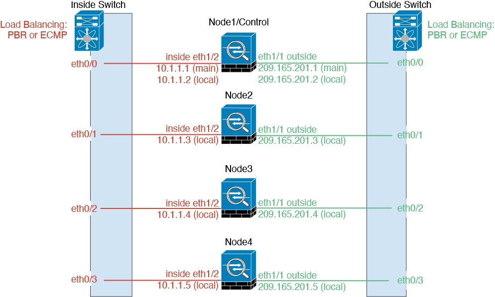
When you place the cluster in your network, the upstream and downstream routers need to be able to load-balance the data coming to and from the cluster using Layer 3 Individual interfaces and one of the following methods:

  • Policy-Based Routing—The upstream and downstream routers perform load balancing between nodes using route maps and ACLs.

  • Equal-Cost Multi-Path Routing—The upstream and downstream routers perform load balancing between nodes using equal cost static or dynamic routes.


(注)  


Layer 2 Spanned EtherChannels are not supported.


制御ノードとデータノードの役割

One member of the cluster is the control node. If multiple cluster nodes come online at the same time, the control node is determined by the priority setting; the priority is set between 1 and 100, where 1 is the highest priority. All other members are data nodes. When you first create the cluster, you specify which node you want to be the control node, and it will become the control node simply because it is the first node added to the cluster.

All nodes in the cluster share the same configuration. The node that you initially specify as the control node will overwrite the configuration on the data nodes when they join the cluster, so you only need to perform initial configuration on the control node before you form the cluster.

Some features do not scale in a cluster, and the control node handles all traffic for those features.

個々のインターフェイス

You can configure cluster interfaces as Individual interfaces.

Individual interfaces are normal routed interfaces, each with their own Local IP address used for routing. The Main cluster IP address for each interface is a fixed address that always belongs to the control node. When the control node changes, the Main cluster IP address moves to the new control node, so management of the cluster continues seamlessly.

IPS-only interfaces (inline sets and passive interfaces) are not supported as Individual interfaces.

Because interface configuration must be configured only on the control node, you configure a pool of IP addresses to be used for a given interface on the cluster nodes, including one for the control node.

Load balancing must be configured separately on the upstream switch.


(注)  


Layer 2 Spanned EtherChannels are not supported.


ポリシーベース ルーティング

When using Individual interfaces, each Firewall Threat Defense interface maintains its own IP address and MAC address. One method of load balancing is Policy-Based Routing (PBR).

We recommend this method if you are already using PBR, and want to take advantage of your existing infrastructure.

PBR makes routing decisions based on a route map and ACL. You must manually divide traffic between all Firewall Threat Defenses in a cluster. Because PBR is static, it may not achieve the optimum load balancing result at all times. To achieve the best performance, we recommend that you configure the PBR policy so that forward and return packets of a connection are directed to the same Firewall Threat Defense. For example, if you have a Cisco router, redundancy can be achieved by using Cisco IOS PBR with Object Tracking. Cisco IOS Object Tracking monitors each Firewall Threat Defense using ICMP ping. PBR can then enable or disable route maps based on reachability of a particular Firewall Threat Defense. See the following URLs for more details:

http://www.cisco.com/c/en/us/solutions/data-center-virtualization/intelligent-traffic-director/index.html

http://www.cisco.com/en/US/products/ps6599/products_white_paper09186a00800a4409.shtml

等コスト マルチパス ルーティング

When using Individual interfaces, each Firewall Threat Defense interface maintains its own IP address and MAC address. One method of load balancing is Equal-Cost Multi-Path (ECMP) routing.

We recommend this method if you are already using ECMP, and want to take advantage of your existing infrastructure.

ECMP routing can forward packets over multiple “best paths” that tie for top place in the routing metric. Like EtherChannel, a hash of source and destination IP addresses and/or source and destination ports can be used to send a packet to one of the next hops. If you use static routes for ECMP routing, then the Firewall Threat Defense failure can cause problems; the route continues to be used, and traffic to the failed Firewall Threat Defense will be lost. If you use static routes, be sure to use a static route monitoring feature such as Object Tracking. We recommend using dynamic routing protocols to add and remove routes, in which case, you must configure each Firewall Threat Defense to participate in dynamic routing.

クラスタ制御リンク

Each node must dedicate one interface as a VXLAN (VTEP) interface for the cluster control link. For more information about VXLAN, see VXLAN インターフェイスの設定.

VXLAN Tunnel Endpoint

VXLAN tunnel endpoint (VTEP) devices perform VXLAN encapsulation and decapsulation. Each VTEP has two interface types: one or more virtual interfaces called VXLAN Network Identifier (VNI) interfaces, and a regular interface called the VTEP source interface that tunnels the VNI interfaces between VTEPs. The VTEP source interface is attached to the transport IP network for VTEP-to-VTEP communication.

VTEP Source Interface

The VTEP source interface is a regular Firewall Threat Defense Virtual interface with which you plan to associate the VNI interface. You can configure one VTEP source interface to act as the cluster control link. The source interface is reserved for cluster control link use only. Each VTEP source interface has an IP address on the same subnet. This subnet should be isolated from all other traffic, and should include only the cluster control link interfaces.

VNI Interface

A VNI interface is similar to a VLAN interface: it is a virtual interface that keeps network traffic separated on a given physical interface by using tagging. You can only configure one VNI interface. Each VNI interface has an IP address on the same subnet.

Peer VTEPs

Unlike regular VXLAN for data interfaces, which allows a single VTEP peer, The Firewall Threat Defense Virtual clustering allows you to configure multiple peers.

クラスタ制御リンク トラフィックの概要

Cluster control link traffic includes both control and data traffic.

Control traffic includes:

  • Control node election.

  • Configuration replication.

  • Health monitoring.

Data traffic includes:

  • State replication.

  • Connection ownership queries and data packet forwarding.

コンフィギュレーションの複製

All nodes in the cluster share a single configuration. You can only make configuration changes on the control node (with the exception of the bootstrap configuration), and changes are automatically synced to all other nodes in the cluster.
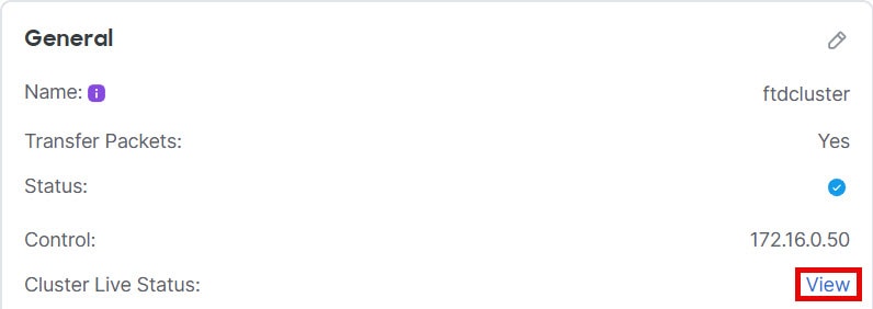
管理ネットワーク

管理インターフェイスを使用して各ノードを管理する必要があります。クラスタリングでは、データインターフェイスからの管理はサポートされていません。

Threat Defense Virtual クラスタリングのライセンス

Firewall Threat Defense Virtual クラスタノードには、同じパフォーマンス階層ライセンスが必要です。すべてのメンバーに同じ数の CPU とメモリを使用することをお勧めします。そうしないと、パフォーマンスが最小能力のメンバーに一致するようにすべてのノードで制限されます。スループットレベルは、一致するように制御ノードから各データノードに複製されます。

個別のノードではなく、クラスタ全体に機能ライセンスを割り当てます。ただし、クラスタの各ノードは機能ごとに個別のライセンスを使用します。クラスタリング機能自体にライセンスは必要ありません。

制御ノードを Firewall Management Center に追加する際に、そのクラスタに使用する機能ライセンスを指定できます。クラスタを作成する前に、データノードにどのライセンスが割り当てられているのかは問題になりません。制御ノードのライセンス設定は、各データノードに複製されます。クラスタのライセンスを変更するには System (system gear icon) > Licenses > Smart Licenses[ライセンスの編集 Licenses)] をクリックするか、 を選択し Devices > Device Management、クラスタの Edit (edit icon) をクリックして、 [ライセンス(License)] 領域で Edit (edit icon)をクリックします。


(注)  


Firewall Management Center にライセンスを取得する(および評価モードで実行する)前にクラスタを追加した場合、Firewall Management Center にライセンスを取得する際にポリシーの変更をクラスタに展開するとトラフィックの中断が発生することがあります。ライセンスモードを変更したことによって、すべてのデータユニットがクラスタをいったん離れてから再参加することになります。


Threat Defense Virtual クラスタリングの要件および前提条件

モデルの要件

  • FTDv5、FTDv10、FTDv20、FTDv30、FTDv50、FTDv100

  • VMware または KVM

  • 4x4 構成のクラスタで最大 16 ノードがサポートされます。最大 4 つのホストを設定し、各ホストに最大 4 つの Threat Defense 仮想インスタンスを設定できます。

User roles

  • Admin

  • Access Admin

  • Network Admin

ハードウェアおよびソフトウェアの要件

クラスタ内のすべてのユニット:

  • クラスタ制御リンクでジャンボフレーム予約を有効にする必要があります。"DeploymentType": "Cluster" を設定して Firewall Threat Defense Virtual を展開するときに、Day 0 構成でこれを実行します。それ以外の場合は、クラスタが形成されて正常な状態になった後で、各ノードを再起動してジャンボフレームを有効にする必要があります。

  • (KVM のみ)KVM ホスト上のすべての VM に CPU ハードパーティショニング(CPU ピン留め)を使用する必要があります。

  • 同じパフォーマンス層である必要があります。すべてのノードに同じ数の CPU とメモリを使用することをお勧めします。そうしないと、パフォーマンスが最小能力のノードに一致するようにすべてのノードで制限されます。

  • Firewall Management Center 通信の管理インターフェイスを指定する必要があります。データインターフェイス管理はサポートされていません。

  • アップグレード時を除き、同じバージョンを実行する必要があります。ヒットレス アップグレードがサポートされます。

  • 同じドメインに属していること。

  • 同じグループに属していること。

  • 保留中または進行中の展開がないこと。

  • 制御ノードにサポート対象外の機能が設定されていないこと:サポートされていない機能とクラスタリング

  • データノードに VPN が設定されていないこと。制御ノードにはサイト間 VPN を設定できます。

Firewall Management Center の要件

Firewall Management Center NTP サーバーをすべてのクラスタノードから到達可能な信頼できるサーバーに設定し、適切にクロックを同期できるようにします。デフォルトでは、デバイスは Firewall Management Center と同じ NTP サーバーが使用されます。すべてのクラスタノードの時刻が同じ時刻に設定されていない場合は、クラスタから自動で削除されます。

スイッチ要件

クラスタリングの設定前にスイッチの設定を完了していること。クラスタ制御リンクに接続されているポートに適切な MTU 値(高い値) が設定されていること。デフォルトでは、クラスタ制御リンクの MTU は、データインターフェイスよりも 154 バイト大きく設定されています。スイッチで MTU が一致しない場合、クラスタの形成に失敗します。

Threat Defense Virtual クラスタリングのガイドライン

ハイ アベイラビリティ

クラスタリングでは、高可用性はサポートされません。

IPv6

クラスタ制御リンクは、IPv4 のみを使用してサポートされます。

その他のガイドライン

  • 重要なトポロジの変更(EtherChannel インターフェイスの追加や削除、Firewall Threat Defense Virtual のインターフェイスの有効化や無効化、VSS または vPC を形成するスイッチの追加、クラスタでの IP アドレスまたはインターフェイスフラップの設定など)が発生した場合は、ヘルスチェック機能を無効にし、トポロジ変更の影響を受けるインターフェイスのインターフェイス モニタリングも無効にする必要があります。トポロジの変更が完了して、コンフィギュレーション変更がすべてのユニットに同期されたら、インターフェイスのヘルス チェック機能を再度有効にできます。

  • ユニットを既存のクラスタに追加したときや、ユニットをリロードしたときは、一時的に、限定的なパケット/接続ドロップが発生します。これは予定どおりの動作です。場合によっては、ドロップされたパケットが原因で接続がハングすることがあります。たとえば、FTP 接続の FIN/ACK パケットがドロップされると、FTP クライアントがハングします。この場合は、FTP 接続を再確立する必要があります。

  • 復号された TLS/SSL 接続の場合、復号状態は同期されず、接続オーナーに障害が発生すると、復号された接続がリセットされます。新しいユニットへの新しい接続を確立する必要があります。復号されていない接続(復号しないルールに一致)は影響を受けず、正しく複製されます。

  • データインターフェイスの VXLAN はサポートしていません。クラスタ制御リンクのみが VXLAN をサポートします。

クラスタリングのデフォルト

  • cLACP システム ID は自動生成され、システムの優先順位はデフォルトでは 1 になっています。

  • クラスタのヘルス チェック機能は、デフォルトで有効になり、ホールド時間は 3 秒です。デフォルトでは、すべてのインターフェイスでインターネット ヘルス モニタリングが有効になっています。

  • 失敗したクラスタ制御リンクのクラスタ再結合機能が 5 分おきに無制限に試行されます。

  • 失敗したデータインターフェイスのクラスタ自動再結合機能は、5 分後と、2 に設定された増加間隔で合計で 3 回試行されます。

  • HTTP トラフィックでは、5 秒間の接続複製遅延がデフォルトで有効になっています。

Threat Defense Virtual クラスタリングの設定

Firewall Threat Defense Virtual の展開後にクラスタリングを設定するには、次のタスクを実行します。

Management Center へのデバイスの追加

クラスタリングを構成する前に、各クラスタノードを展開してから、Firewall Management Center でデバイスをスタンドアロンユニットとして追加します。

手順


ステップ 1

Secure Firewall Threat Defense Virtual getting started guides』[英語] に従って各クラスタノードを展開します。

クラスタ内のすべてのユニット:

  • クラスタ制御リンクでジャンボフレーム予約を有効にする必要があります。"DeploymentType": "Cluster" を設定して Firewall Threat Defense Virtual を展開するときに、Day 0 構成でこれを実行します。それ以外の場合は、クラスタが形成されて正常な状態になった後で、各ノードを再起動してジャンボフレームを有効にする必要があります。

  • (KVM のみ)KVM ホスト上のすべての VM に CPU ハードパーティショニング(CPU ピン留め)を使用する必要があります。

ステップ 2

同じドメインおよびグループ内のスタンドアロンデバイスとして、各ノードを Firewall Management Center に追加します。

登録キーを使用したデバイスの追加(従来の画面):基本設定を参照してください。単一のデバイスでクラスタを作成し、後からノードを追加できます。デバイスを追加したときに行った初期設定(ライセンス、アクセス コントロール ポリシー)は、制御ノードからすべてのクラスタノードに継承されます。クラスタを形成するときに制御ノードを選択します。


クラスタの作成

Firewall Management Center 内の 1 台以上のデバイスでクラスタを形成します。

始める前に

一部の機能はクラスタリングに対応していません。そのため、クラスタリングを有効にしてから、設定を行う必要があります。一部の機能は、設定してしまうとクラスタの作成をブロックします。たとえば、インターフェイスに IP アドレスを設定したり、BVI などのサポート対象外のインターフェイスタイプを設定したりしないでください。

手順


ステップ 1

[デバイス(Devices)] > [デバイス管理(Device Management)] の順に選択してから、[追加(Add)] > [クラスタ(Cluster)] の順に選択します。 > >

[クラスタの追加(Add Cluster)] ウィザードが表示されます。

図 1. [クラスタの追加(Add Cluster)] ウィザード
[クラスタの追加(Add Cluster)] ウィザード

ステップ 2

制御トラフィックの [クラスタ名(Cluster Name)] と認証用の [クラスタキー(Cluster Key)] を指定します。

  • [クラスタ名(Cluster Name)]:1 ~ 38 文字の ASCII 文字列。

  • [クラスタキー(Cluster Key)]:1 ~ 63 文字の ASCII 文字列。[クラスタキー(Cluster Key)] の値は暗号キーを生成するために使用されます。この暗号は、データパストラフィック(接続状態の更新や転送されるパケットなど)には影響しません。データパストラフィックは、常にクリアテキストとして送信されます。

ステップ 3

[制御ノード(Control Node)] については、次のように設定します。

  • [ノード(Node)]:最初に制御ノードにするデバイスを選択します。Firewall Management Center がクラスタを形成すると、このノードが最初にクラスタに追加されて制御ノードになります。

    (注)  


    ノード名の横に Error (error icon) アイコンが表示されている場合は、そのアイコンをクリックして設定の問題を表示します。クラスタの形成をキャンセルし、問題を解決してからクラスタの形成に戻る必要があります。次に例を示します。

    図 2. 設定の問題
    設定の問題

    上記の問題を解決するには、サポート対象外の VPN ライセンスを削除し、保留中の設定の変更をデバイスに展開します。

  • [VXLANネットワーク識別子(VNI)ネットワーク(VXLAN Network Identifier (VNI) Network)]:VNI ネットワークの IPv4 サブネットを指定します。このネットワークでは IPv6 はサポートされていません。[24]、[25]、[26]、または [27] サブネットを指定します。IP アドレスは、このネットワーク上の各ノードに自動的に割り当てられます。VNI ネットワークは、物理 VTEP ネットワーク上で稼働する暗号化された仮想ネットワークです。

  • [クラスタ制御リンク(Cluster Control Link)]:クラスタ制御リンクに使用する物理インターフェイスを選択します。

  • [仮想トンネルエンドポイント(VTEP)ネットワーク(Virtual Tunnel Endpoint (VTEP) Network)]:物理インターフェイス ネットワークの IPv4 サブネットを指定します。このネットワークでは IPv6 はサポートされていません。VTEP ネットワークは VNI ネットワークとは別のネットワークであり、物理クラスタ制御リンクに使用されます。

  • [VTEP IPv4 アドレス(VTEP IPv4 Address)]:このフィールドには、VTEP ネットワークの最初のアドレスが自動的に入力されます。

  • [プライオリティ(Priority)]:制御ノードの選択に対するこのノードのプライオリティを設定します。プライオリティは 1 ~ 100 であり、1 が最高のプライオリティです。他のノードよりプライオリティを低く設定しても、クラスタが最初に形成されたときは、このノードが引き続き制御ノードになります。

ステップ 4

[データノード(Data Nodes)](オプション)で、[データノードを追加(Add a data node)] をクリックしてクラスタにノードを追加します。

クラスタの形成を高速化するために制御ノードのみでクラスタを形成することも、すべてのノードをここで追加することも可能です。各データノードで以下を設定します。

  • [ノード(Node)]:追加するデバイスを選択します。

    (注)  


    ノード名の横に Error (error icon) アイコンが表示されている場合は、そのアイコンをクリックして設定の問題を表示します。クラスタの形成をキャンセルし、問題を解決してからクラスタの形成に戻る必要があります。

  • [VTEP IPv4 アドレス(VTEP IPv4 Address)]:このフィールドには、VTEP ネットワークの次のアドレスが自動的に入力されます。

  • [プライオリティ(Priority)]:制御ノードの選択に対するこのノードのプライオリティを設定します。プライオリティは 1 ~ 100 であり、1 が最高のプライオリティです。

ステップ 5

[続行(Continue)] をクリックします。[概要(Summary)] を確認し、[保存(Save)] をクリックします。

クラスタブートストラップ構成は、クラスタノードに保存されます。ブートストラップ構成には、クラスタ制御リンクに使用される VXLAN インターフェイスが含まれています。

[デバイス(Devices)] > [デバイス管理(Device Management)] ページにクラスタ名が表示されます。クラスタを展開して、クラスタノードを表示します。

図 3. クラスタの管理
クラスタの管理

現在登録中のノードには、ロードアイコンが表示されます。

図 4. ノードの登録
ノードの登録
クラスタノードの登録をモニターするには、[通知(Notifications)] アイコンをクリックし、[タスク(Tasks)] を選択します。Firewall Management Center は、ノードの登録ごとにクラスタ登録タスクを更新します。

ステップ 6

クラスタの Edit (edit icon) をクリックして、デバイス固有の設定を指定します。

ほとんどの設定は、クラスタ内のノードではなく、クラスタ全体に適用できます。たとえば、ノードごとに表示名を変更できますが、インターフェイスはクラスタ全体についてのみ設定できます。

ステップ 7

[デバイス(Devices)] > [デバイス管理(Device Management)] > [クラスタ(Cluster)] 画面に、クラスタの [全般(General)] などの設定が表示されます。

図 5. クラスタ設定
クラスタ設定
[全般(General)] 領域には、次のクラスタに固有の項目が表示されます。
  • [全般(General)] > [名前(Name)]:Edit (edit icon) をクリックして、クラスタの表示名を変更します。

    その後に、[名前(Name)] フィールドを設定します。

  • [全般(General)] > [表示(View)]:[表示(View)] リンクをクリックして [クラスタステータス(Cluster Status)] ダイアログボックスを開きます。

    [クラスタステータス(Cluster Status)] ダイアログボックスでは、[すべて照合(Reconcile All)] をクリックしてデータユニットの登録を再試行することもできます。ノードからクラスタ制御リンクに ping を実行することもできます。クラスター制御リンクへの ping の実行を参照してください。

  • [全般(General)] > [トラブルシュート(Troubleshoot)]:トラブルシューティングログを生成およびダウンロードしたり、クラスタ CLI を表示したりできます。クラスタのトラブルシューティングを参照してください。

    図 6. トラブルシューティング
    トラブルシューティング

ステップ 8

[デバイス(Devices)] > [デバイス管理(Device Management)] > [デバイス(Devices)] の右上のドロップダウンメニューで、クラスタ内の各メンバーを選択し、次の設定を指定することができます。

図 7. デバイス設定
デバイス設定
図 8. ノードの選択
ノードの選択
  • [全般(General)] > [名前(Name)]:Edit (edit icon) をクリックして、クラスタメンバーの表示名を変更します。

    その後に、[名前(Name)] フィールドを設定します。

  • [管理(Management)] > [ホスト(Host)]:デバイス設定で管理 IP アドレスを変更する場合は、Firewall Management Center で新しいアドレスを一致させてネットワーク上のデバイスに到達できるようにする必要があります。最初に接続を無効にし、[管理(Management)] 領域で [ホスト(Host)] のアドレスを編集してから、接続を再度有効にします。

ステップ 9

ジャンボフレームの予約を有効にせずにクラスタノードを展開した場合は、すべてのクラスタノードを再起動して、クラスタ制御リンクに必要なジャンボフレームを有効にします。デバイスのシャットダウンまたは再起動を参照してください。

事前にジャンボフレームの予約を有効にした場合は、この手順をスキップできます。

クラスタ制御リンクのトラフィックにはデータパケット転送が含まれるため、クラスタ制御リンクはデータパケット全体のサイズに加えてクラスタトラフィックのオーバーヘッド(100 バイト)および VXLAN のオーバーヘッド(54 バイト)にも対応する必要があります。クラスタを作成すると、MTU はデータインターフェイスの最大 MTU(デフォルトでは 1654)よりも 154 バイト大きい値が設定されます。後でデータインターフェイスの MTU を増やす場合は、クラスタ制御リンクの MTU も増やすようにしてください。たとえば、最大 MTU は 9198 バイトであるため、データインターフェイスの最大 MTU は 9044 になり、クラスタ制御リンクは 9198 に設定できます。 MTU の設定を参照してください。

(注)  


クラスタ制御リンクに接続されているスイッチの MTU を適切な値(高い値)に設定してください。そうしないと、クラスタ形成に失敗します。クラスタに参加したノードは、クラスタ制御リンク MTU と一致するパケットサイズで制御ノードに ping を送信することで MTU の互換性をチェックします。ping が失敗すると、通知が生成されるため、接続スイッチの MTU 不一致を修正して再試行することができます。


インターフェイスの設定

ここでは、個々のインターフェイスがクラスタリング互換となるようにインターフェイスを設定する方法について説明します。個別インターフェイスは通常のルーテッド インターフェイスであり、それぞれが専用の IP アドレスを IP アドレス プールから取得します。メインクラスタ IP アドレスは、そのクラスタのための固定アドレスであり、常に現在の制御ノードに属します。すべてのデータインターフェイスは個別インターフェイスである必要があります。


(注)  


サブインターフェイスは使用できません。


手順


ステップ 1

[オブジェクト(Objects)] > [オブジェクト管理(Object Management)] > [アドレスプール(Address Pools)] を選択して、IPv4 または IPv6 アドレスプールを追加します。 アドレス プールを参照してください。

最低でも、クラスタ内のユニット数と同じ数のアドレスが含まれるようにしてください。仮想 IP アドレスはこのプールには含まれませんが、同一ネットワーク上に存在している必要があります。各ユニットに割り当てられる正確なローカル アドレスを事前に決定することはできません。

ステップ 2

[デバイス(Devices)] > [デバイス管理(Device Management)] を選択し、クラスタの横にある Edit (edit icon) をクリックします。

ステップ 3

[インターフェイス(Interfaces)] をクリックし、データインターフェイスの Edit (edit icon) をクリックします。

ステップ 4

[IPv4] で [IPアドレス(IP Address)] とマスクを入力します。この IP アドレスは、そのクラスタの固定アドレスで、常に現在の制御ユニットに属します。

ステップ 5

作成したアドレスプールを [IPv4アドレスプール(IPv4 Address Pool) ] ドロップダウンリストから選択します。

(注)  


このインターフェイスに MAC アドレスを手動で割り当てる場合は、FlexConfig を使用して mac-address pool を作成する必要があります。

ステップ 6

[IPv6] > [基本(Basic)] で、[IPv6アドレスプール(IPv6 Address Pool)] ドロップダウンリストから、作成したアドレスプールを選択します。

ステップ 7

通常どおり、他のインターフェイス設定を行います。

ステップ 8

[Save(保存)] をクリックします。

これで、Deploy > Deploy に移動して、ポリシーを割り当てたデバイスにデプロイします。変更内容は導入するまで適用されません。


クラスタのヘルスモニターの設定

[クラスタ(Cluster)] ページの [クラスタヘルスモニターの設定(Cluster Health Monitor Settings)] セクションには、次の表で説明されている設定が表示されます。

図 9. クラスタのヘルスモニターの設定
クラスタのヘルスモニターの設定
表 1. [クラスタヘルスモニターの設定(Cluster Health Monitor Settings)] セクションテーブルのフィールド

フィールド

説明

タイムアウト(Timeouts)

保留時間(Hold Time)

指定できる範囲は 0.3 ~ 45 秒です。デフォルトは 3 秒です。ノードの状態を確認するため、クラスタノードはクラスタ制御リンクで他のノードにハートビートメッセージを送信します。ノードが保留時間内にピアノードからハートビートメッセージを受信しない場合、そのピアノードは応答不能またはデッド状態と見なされます。

インターフェイスのデバウンス時間(Interface Debounce Time)

指定できる範囲は 300 ~ 9000 ミリ秒です。デフォルトは 500 ms です。インターフェイスのデバウンス時間は、インターフェイスで障害が発生していると見なされ、クラスタからノードが削除されるまでの時間です。

Monitored Interfaces(モニタリング対象インターフェイス)

インターフェイスのヘルス チェックはリンク障害をモニターします。特定の論理インターフェイスのすべての物理ポートが、特定のノード上では障害が発生したが、別のノード上の同じ論理インターフェイスでアクティブポートがある場合、そのノードはクラスタから削除されます。ノードがメンバーをクラスタから削除するまでの時間は、インターフェイスのタイプと、そのノードが確立済みノードであるか、またはクラスタに参加しようとしているかによって異なります。

サービスアプリケーション(Service Application)

Snort プロセスおよび disk-full プロセスが監視されているかどうかを示します。

モニタリング対象外のインターフェイス(Unmonitored Interfaces)

モニタリング対象外のインターフェイスを表示します。

自動再結合の設定(Auto-Rejoin Settings)

クラスタインターフェイス(Cluster Interface)

クラスタ制御リンクに障害が発生した後に自動再結合の設定を表示します。

試行(Attempts)

指定できる範囲は -1 ~ 65535 です。デフォルトは -1(無制限)です。再結合の試行回数を設定します。

試行の間隔(Interval Between Attempts)

指定できる範囲は 2 ~ 60 です。デフォルトは 5 分です。再結合試行の間隔を分単位で定義します。

間隔のバリエーション(Interval Variation)

指定できる範囲は 1 ~ 3 です。デフォルトは間隔の 1 倍です。試行ごとに間隔を長くするかどうかを定義します。

データインターフェイス(Data Interfaces)

データインターフェイスに障害が発生した後に自動再結合の設定を表示します。

試行(Attempts)

指定できる範囲は -1 ~ 65535 です。デフォルトは 3 です。再結合の試行回数を設定します。

試行の間隔(Interval Between Attempts)

指定できる範囲は 2 ~ 60 です。デフォルトは 5 分です。再結合試行の間隔を分単位で定義します。

間隔のバリエーション(Interval Variation)

指定できる範囲は 1 ~ 3 です。デフォルトは間隔の 2 倍です。試行ごとに間隔を長くするかどうかを定義します。

システム(System)

内部エラーが発生した後に自動再結合の設定を表示します。内部エラーには、アプリケーション同期のタイムアウト、一貫性のないアプリケーションステータスなどがあります。

試行(Attempts)

指定できる範囲は -1 ~ 65535 です。デフォルトは 3 です。再結合の試行回数を設定します。

試行の間隔(Interval Between Attempts)

指定できる範囲は 2 ~ 60 です。デフォルトは 5 分です。再結合試行の間隔を分単位で定義します。

間隔のバリエーション(Interval Variation)

指定できる範囲は 1 ~ 3 です。デフォルトは間隔の 2 倍です。試行ごとに間隔を長くするかどうかを定義します。


(注)  


システムのヘルスチェックを無効にすると、システムのヘルスチェックが無効化されている場合に適用されないフィールドは表示されません。


これらの設定は、このセクションから変更できます。

任意のポートチャネル ID、単一の物理インターフェイス ID、Snort プロセス、および disk-full プロセスを監視できます。ヘルス モニタリングは VLAN サブインターフェイス、または VNI や BVI などの仮想インターフェイスでは実行されません。クラスタ制御リンクのモニタリングは設定できません。このリンクは常にモニタされています。

手順


ステップ 1

Devices > Device Management を選択します。 

ステップ 2

変更するクラスタの横にある Edit (edit icon) をクリックします。

ステップ 3

[クラスタ(Cluster)] をクリックします。

ステップ 4

[クラスタのヘルスモニターの設定(Cluster Health Monitor Settings)] セクションで、Edit (edit icon) をクリックします。 

ステップ 5

[ヘルスチェック(Health Check)] スライダをクリックして、システムのヘルスチェックを無効にします。

図 10. システムヘルスチェックの無効化
システムのヘルスチェックの無効化

何らかのトポロジ変更(たとえばデータインターフェイスの追加/削除、ノードやスイッチのインターフェイスの有効化/無効化、VSS や vPC(または VNet)を形成するスイッチの追加)を行うときには、システムのヘルスチェック機能を無効にし、無効化したインターフェイスのモニタリングも無効にしてください。トポロジの変更が完了して、設定の変更がすべてのノードに同期されたら、システムのヘルスチェック機能を再度有効にてインターフェイスをモニタリングできます。

ステップ 6

ホールド時間とインターフェイスのデバウンス時間を設定します。

  • [ホールド時間(Hold Time)]:ノードのハートビート ステータス メッセージの時間間隔を指定します。指定できる範囲は 3 ~ 45 秒で、デフォルトは 3 秒です。

  • [インターフェイスのデバウンス時間(Interface Debounce Time)]:デバウンス時間は 300 ~ 9000 ms の範囲で値を設定します。デフォルトは 500 ms です。値を小さくすると、インターフェイスの障害をより迅速に検出できます。デバウンス時間を短くすると、誤検出の可能性が高くなることに注意してください。インターフェイスのステータス更新が発生すると、インターフェイス障害としてマーク付けされるまで、ノードは指定されたミリ秒数待機します。その後、ノードはクラスタから削除されます。EtherChannel がダウン状態からアップ状態に移行する場合(スイッチがリロードされた、スイッチで EtherChannel が有効になったなど)、デバウンス時間がより長くなり、ポートのバンドルにおいて別のクラスタノードの方が高速なため、クラスタノードでインターフェイスの障害が表示されることを妨げることがあります。

ステップ 7

ヘルス チェック失敗後の自動再結合クラスタ設定をカスタマイズします。

図 11. 自動再結合の設定
自動再結合の設定
[クラスタインターフェイス(Cluster Interface)]、[データインターフェイス(Data Interface)]、および [システム(System)] に次の値を設定します(内部エラーには、アプリケーションの同期タイムアウト、一貫性のないアプリケーションステータスなどがあります)。
  • [試行数(Attempts)]:再結合の試行回数を 0 ~ 65535 の範囲の値に設定します。0 は自動再結合を無効化します。[クラスタインターフェイス(Cluster Interface)] のデフォルト値は -1(無制限)です。 [データインターフェイス(Data Interface)] と [システム(System)] のデフォルト値は 3 です。

  • [試行の間隔(Interval Between Attempts)]:再結合試行の間隔を 2 ~ 60 の分単位で定義します。デフォルト値は 5 分です。クラスタへの再参加をノードが試行する最大合計時間は、最後の障害発生時から 14400 分(10 日)に制限されます。

  • [間隔のバリエーション(Interval Variation)]:間隔を増加させるかどうかを定義します。1 ~ 3 の範囲で値を設定します(1:変更なし、2:直前の間隔の 2 倍、3:直前の間隔の 3 倍)。たとえば、間隔を 5 分に設定し、変分を 2 に設定した場合は、最初の試行が 5 分後、2 回目の試行が 10 分後(2 x 5)、3 階目の試行が 20 分後(2 x 10)となります。デフォルト値は、[クラスタインターフェイス(Cluster Interface)] の場合は 1、[データインターフェイス(Data Interface)] および [システム(System)] の場合は 2 です。

ステップ 8

[モニタリング対象のインターフェイス(Monitored Interfaces)] または [モニタリング対象外のインターフェイス(Unmonitored Interfaces)] ウィンドウでインターフェイスを移動して、モニタリング対象のインターフェイスを設定します。[サービスアプリケーションのモニタリングを有効にする(Enable Service Application Monitoring)] をオンまたはオフにして、Snort プロセスと disk-full プロセスのモニタリングを有効または無効にすることもできます。

図 12. モニタリング対象インターフェイスの設定
モニタリング対象インターフェイスの設定

インターフェイスのヘルス チェックはリンク障害をモニターします。特定の論理インターフェイスのすべての物理ポートが、特定のノード上では障害が発生したが、別のノード上の同じ論理インターフェイスでアクティブポートがある場合、そのノードはクラスタから削除されます。ノードがメンバーをクラスタから削除するまでの時間は、インターフェイスのタイプと、そのノードが確立済みノードであるか、またはクラスタに参加しようとしているかによって異なります。デフォルトでは、ヘルスチェックはすべてのインターフェイス、および Snort プロセスと disk-full プロセスで有効になっています。

必須以外のインターフェイスのヘルス モニタリングを無効にできます。

何らかのトポロジ変更(たとえばデータインターフェイスの追加/削除、ノードやスイッチのインターフェイスの有効化/無効化、VSS や vPC(または VNet)を形成するスイッチの追加)を行うときには、システムのヘルスチェック機能を無効にし、無効化したインターフェイスのモニタリングも無効にしてください。トポロジの変更が完了して、設定の変更がすべてのノードに同期されたら、システムのヘルスチェック機能を再度有効にてインターフェイスをモニタリングできます。

ステップ 9

[保存(Save)] をクリックします。

ステップ 10

設定変更を展開します設定変更の展開を参照してください


クラスタノードの管理

新しいクラスタノードの追加

1 つ以上の新しいクラスタノードを既存のクラスタに追加できます。

手順


ステップ 1

[デバイス(Devices)] > [デバイス管理(Device Management)] の順に選択し、クラスタの More (more icon) をクリックして [ノードを追加(Add Nodes)] を選択します。

図 13. ノードの追加
ノードの追加

[クラスタの管理(Manage Cluster)] ウィザードが表示されます。

ステップ 2

[ノード(Node)] メニューからデバイスを選択し、必要に応じて IP アドレスと優先順位を調整します。

図 14. [クラスタの管理(Manage Cluster)] ウィザード
[クラスタの管理(Manage Cluster)] ウィザード

ステップ 3

さらにノードを追加するには、[データノードを追加(Add a data node)] をクリックします。

ステップ 4

[続行(Continue)] をクリックします。[概要(Summary)] を確認し、[保存(Save)] をクリックします。

現在登録されているノードには、ロードアイコンが表示されます。

図 15. ノードの登録
ノードの登録

クラスタノードの登録をモニターするには、[通知(Notifications)] アイコンをクリックし、[タスク(Tasks)] を選択します。


ノードの除外

ノードがスタンドアロンデバイスになるように、クラスからノードを削除できます。クラスタ全体を解除しない限り、制御ノードを除外することはできません。データノードの設定は消去されます。

手順


ステップ 1

[デバイス(Devices)] > [デバイス管理(Device Management)] の順に選択し、除外するノードの More (more icon) をクリックして [ノードを除外(Break Node)] を選択します。

図 16. ノードの除外
ノードの除外

オプションで、クラスタの [詳細(More)] メニューから [ノードを除外(Break Nodes)] を選択して 1 つ以上のノードを除外できます。

ステップ 2

除外の確定を求められたら、[はい(Yes)] をクリックします。

図 17. 解除の確定
解除の確定

クラスタノードの除外をモニターするには、[通知(Notifications)] アイコンをクリックし、[タスク(Tasks)] を選択します。


クラスタの解除

クラスタを解除し、すべてのノードをスタンドアロンデバイスに変換できます。制御ノードはインターフェイスとセキュリティポリシーの設定を保持しますが、データノードでは設定が消去されます。

手順


ステップ 1

ノードを照合することにより、すべてのクラスタノードが Firewall Management Center で管理されていることを確認します。クラスタノードの照合を参照してください。

ステップ 2

[デバイス(Devices)] > [デバイス管理(Device Management)] の順に選択し、クラスタの More (more icon) をクリックして [クラスタを解除(Break Cluster)] を選択します。

図 18. クラスタの解除
クラスタの解除

ステップ 3

クラスタを解除するよう求められたら、[はい(Yes)] をクリックします。

図 19. 解除の確定
解除の確定

クラスタの解除をモニターするには、[通知(Notifications)] アイコンをクリックし、[タスク(Tasks)] を選択します。


クラスタリングを無効にする

ノードの削除に備えて、またはメンテナンスのために一時的にノードを非アクティブ化する場合があります。この手順は、ノードを一時的に非アクティブ化するためのものです。ノードは引き続き Firewall Management Center のデバイスリストに表示されます。ノードが非アクティブになると、すべてのデータインターフェイスがシャットダウンされます。

手順


ステップ 1

無効にするユニットに対して、[デバイス(Devices)] > [デバイス管理(Device Management)] の順に選択して More (more icon) をクリックし、[ノードのクラスタリングを無効にする(Disable Node Clustering)] を選択します。

図 20. クラスタリングを無効にする
クラスタリングを無効にする

制御ノードでクラスタリングを無効にすると、データノードの 1 つが新しい制御ノードになります。なお、中央集中型機能については、制御ノード変更を強制するとすべての接続がドロップされるため、新しい制御ノード上で接続を再確立する必要があります。制御ノードがクラスタ内の唯一のノードである場合、そのノードでクラスタリングを無効にすることはできません。

ステップ 2

ノードのクラスタリングを無効にすることを確認します。

ノードは、[デバイス(Devices)] > [デバイス管理(Device Management)] リストの名前の横に [(無効(Disabled))] と表示されます。

ステップ 3

クラスタリングを再び有効にするには、クラスタへの再参加を参照してください。


クラスタへの再参加

(たとえば、インターフェイスで障害が発生したために)ノードがクラスタから削除された場合、または手動でクラスタリングを無効にした場合は、クラスタに手動で再参加する必要があります。クラスタへの再参加を試行する前に、障害が解決されていることを確認します。ノードをクラスタから削除できる理由の詳細については、「クラスタへの再参加」を参照してください。

手順


ステップ 1

再度有効にするユニットに対して、[デバイス(Devices)] > [デバイス管理(Device Management)] の順に選択して More (more icon) をクリックし、[ノードのクラスタリングを有効にする(Enable Node Clustering)] を選択します。 >

ステップ 2

ノードのクラスタリングを有効にすることを確認します。


制御ノードの変更


注意    


制御ノードを変更する最良の方法は、制御ノードでクラスタリングを無効にし、新しい制御ユニットの選択を待ってから、クラスタリングを再度有効にする方法です。制御ノードにするユニットを厳密に指定する必要がある場合は、このセクションの手順を使用します。なお、中央集中型機能については、いずれかの方法で制御ノード変更を強制するとすべての接続がドロップされるため、新しい制御ノード上で接続を再確立する必要があります。


制御ノードを変更するには、次の手順を実行します。

手順


ステップ 1

[デバイス(Devices)] > [デバイス管理(Device Management)] > More (more icon) > [クラスタのライブステータス(Cluster Live Status)] を選択して [クラスタステータス(Cluster Status)] ダイアログボックスを開きます。

図 21. クラスタのステータス
クラスタのステータス

ステップ 2

制御ユニットにしたいユニットについて、More (more icon) > [ロールを制御に変更(Change Role to Control)] を選択します。

ステップ 3

ロールの変更を確認するように求められます。チェックボックスをオンにして [OK] をクリックします。


クラスタ設定の編集

クラスタ設定を編集できます。ノードの VTEP IP アドレスまたはノードの優先順位以外の値を変更すると、クラスタは自動的に失われて再構築されます。クラスタが再形成されるまで、トラフィックの中断が発生する可能性があります。ノードの VTEP IP アドレスやノードの優先順位を変更すると、影響を受けるノードのみが除外されてクラスタに再追加されます。

手順


ステップ 1

[デバイス(Devices)] > [デバイス管理(Device Management)] の順に選択し、クラスタの More (more icon) をクリックして [設定を編集(Edit Configuration)] を選択します。

図 22. 設定の編集
設定の編集

[クラスタの管理(Manage Cluster)] ウィザードが表示されます。

ステップ 2

クラスタ設定を更新します。

図 23. [クラスタの管理(Manage Cluster)] ウィザード
[クラスタの管理(Manage Cluster)] ウィザード

ステップ 3

[続行(Continue)] をクリックします。[概要(Summary)] を確認し、[保存(Save)] をクリックします。


クラスタノードの照合

クラスタノードの登録に失敗した場合は、デバイスから Firewall Management Center に対してクラスタメンバーシップを照合できます。たとえば、Firewall Management Center が特定のプロセスで占領されているか、ネットワークに問題がある場合、データノードの登録に失敗することがあります。

手順


ステップ 1

クラスタの [Devices] > [Device Management] > More (more icon) を選択し、次に [Cluster Live Status] を選択して [Cluster Status] ダイアログボックスを開きます。

図 24. クラスタのライブステータス
クラスタのライブステータス

ステップ 2

[すべてを照合(Reconcile All)] をクリックします。

図 25. すべてを照合
すべてを照合

クラスタ ステータスの詳細については、クラスタのモニタリングを参照してください。


クラスタまたはノードの削除(登録解除)と新しい Firewall Management Center への登録

Firewall Management Center からクラスタを登録解除できます。これにより、クラスタはそのまま維持されます。クラスタを新しい Firewall Management Center に追加する場合は、クラスタを登録解除することができます。

クラスタからノードを除外することなく、Firewall Management Center からノードを登録解除することもできます。ノードは Firewall Management Center に表示されていませんが、まだクラスタの一部であり、引き続きトラフィックを渡して制御ノードになることも可能です。現在動作している制御ノードを登録解除することはできません。Firewall Management Center から到達不可能になったノードは登録解除してもかまいませんが、管理接続をトラブルシューティングする間、クラスタの一部として残しておくことも可能です。

クラスタの登録解除:

  • Firewall Management Center とクラスタとの間のすべての通信が切断されます。

  • [デバイス管理(Device Management)] ページからクラスタが削除されます。

  • クラスタのプラットフォーム設定ポリシーで、NTP を使用して Firewall Management Center から時間を受信するように設定されている場合は、クラスタがローカル時間管理に戻されます。

  • 設定はそのままになるため、クラスタはトラフィックの処理を続行します。

    NAT や VPN などのポリシー、ACL、およびインターフェイス構成は維持されます。

同じまたは別の Firewall Management Center にクラスタを再登録すると、設定が削除されるため、クラスタはその時点でトラフィックの処理を停止します。クラスタ設定はそのまま維持されるため、クラスタ全体を追加できます。登録時にアクセス コントロール ポリシーを選択できますが、トラフィックを再度処理する前に、登録後に他のポリシーを再適用してから設定を展開する必要があります。

始める前に

この手順では、いずれかのノードへの CLI アクセスが必要です。

手順


ステップ 1

Devices > Device Management を選択し、クラスターまたはノードの More (more icon) をクリックして、[登録解除(Unregister)] を選択します。

図 26. クラスタまたはノードの登録解除
クラスタまたはノードの登録解除

ステップ 2

クラスタかノードを登録解除するよう求められたら、[はい(Yes)] をクリックします。

ステップ 3

クラスタメンバーの 1 つを新しいデバイスとして追加することにより、クラスタを新しい(または同じ)Firewall Management Center に登録できます。

  1. 1 つのクラスタノードの CLI に接続し、configure manager add コマンドを使用して新しい Firewall Management Center を識別します。「Threat Defense 管理インターフェイスの CLI での変更」を参照してください。

  2. Devices > Device Management を選択し、[デバイスの追加(Add Device)] をクリックします。

    クラスタノードの 1 つをデバイスとして追加するだけで、残りのクラスタノードが検出されます。

ステップ 4

削除したノードを再度追加する方法については、「クラスタノードの照合」を参照してください。


クラスタのモニタリング

クラスタは、Firewall Management CenterFirewall Threat Defense の CLI でモニターできます。

  • [クラスタステータス(Cluster Status)] ダイアログボックスには、[デバイス(Devices)] > [デバイス管理(Device Management)] > More (more icon) アイコンから、または [デバイス(Devices)] > [デバイス管理(Device Management)] > [クラスタ(Cluster)] ページ > [全般(General)] 領域 > [クラスタのライブステータス(Cluster Live Status)] リンクからアクセスできます。 > > >

    図 27. クラスタのステータス
    クラスタのステータス

    制御ノードには、そのロールを示すグラフィックインジケータがあります。

    クラスタメンバーステータスには、次の状態が含まれます。

    • 同期中(In Sync):ノードは Firewall Management Center に登録されています。

    • 登録の保留中(Pending Registration):ノードはクラスタの一部ですが、まだ Firewall Management Center に登録されていません。ノードの登録に失敗した場合は、[すべてを照合(Reconcile All)] をクリックして登録を再試行できます。

    • クラスタリングが無効(Clustering is disabled):ノードは Firewall Management Center に登録されていますが、クラスタの非アクティブなメンバーです。クラスタリング設定は、後で再有効化する予定がある場合は変更せずに維持できます。また、ノードをクラスタから削除することも可能です。

    • クラスタに参加中...(Joining cluster...):ノードがシャーシ上でクラスタに参加していますが、参加は完了していません。参加後に Firewall Management Center に登録されます。

    ノードごとに [概要(Summary)] と [履歴(History)] を表示できます。

    図 28. ノードの [概要(Summary)]
    ノードの [概要(Summary)]
    図 29. ノードの [履歴(History)]
    ノードの [履歴(History)]
  • System (system gear icon) > [Tasks] ページ。

    [タスク(Tasks)] ページには、ノードが登録されるたびにクラスタ登録タスクの最新情報が表示されます。

  • [デバイス(Devices)] > [デバイス管理(Device Management)] > cluster_name。 >

    デバイスの一覧表示ページでクラスタを展開すると、IP アドレスの横にそのロールが表示されている制御ノードを含む、すべてのメンバーノードを表示できます。登録中のノードには、ロード中のアイコンが表示されます。

  • show cluster {access-list [acl_name] | conn [count] | cpu [usage] | history | interface-mode | memory | resource usage | service-policy | traffic | xlate count}

    クラスタ全体の集約データまたはその他の情報を表示するには、show cluster コマンドを使用します。

  • show cluster info [auto-join | clients | conn-distribution | flow-mobility counters | goid [options] | health | incompatible-config | loadbalance | old-members | packet-distribution | trace [options] | transport { asp | cp}]

    クラスタ情報を表示するには、show cluster info コマンドを使用します。

クラスタ ヘルス モニター ダッシュボード

クラスタのヘルスモニター

Firewall Threat Defense がクラスタの制御ノードである場合、Firewall Management Center はデバイス メトリック データ コレクタからさまざまなメトリックを定期的に収集します。クラスタの ヘルスモニターは、次のコンポーネントで構成されています。

  • 概要ダッシュボード:クラスタトポロジ、クラスタ統計、およびメトリックチャートに関する情報を表示します。

    • トポロジセクションには、クラスタのライブステータス、個々の脅威防御の状態、脅威防御ノードのタイプ(制御ノードまたはデータノード)、およびデバイスの状態が表示されます。デバイスの状態は、[無効(Disabled)](デバイスがクラスタを離れたとき)、[初期状態で追加(Added out of box)](パブリッククラウドクラスタで Firewall Management Center に属していない追加ノード)、または [標準(Normal)](ノードの理想的な状態)のいずれかです。

    • クラスタの統計セクションには、CPU 使用率、メモリ使用率、入力レート、出力レート、アクティブな接続数、および NAT 変換数に関するクラスタの現在のメトリックが表示されます。


      (注)  


      CPU とメモリのメトリックは、データプレーンと Snort の使用量の個々の平均を示します。


    • メトリックチャート、つまり、CPU 使用率、メモリ使用率、スループット、および接続数は、指定された期間におけるクラスタの統計を図表で示します。

  • 負荷分散ダッシュボード:2 つのウィジェットでクラスタノード全体の負荷分散を表示します。

    • 分布ウィジェットには、クラスタノード全体の時間範囲における平均パケットおよび接続分布が表示されます。このデータは、ノードによって負荷がどのように分散されているかを示します。このウィジェットを使用すると、負荷分散の異常を簡単に特定して修正できます。

    • ノード統計ウィジェットには、ノードレベルのメトリックが表形式で表示されます。クラスタノード全体の CPU 使用率、メモリ使用率、入力レート、出力レート、アクティブな接続数、および NAT 変換数に関するメトリックデータが表示されます。このテーブルビューでは、データを関連付けて、不一致を簡単に特定できます。

  • メンバー パフォーマンス ダッシュボード:クラスタノードの現在のメトリックを表示します。セレクタを使用してノードをフィルタリングし、特定ノードの詳細を表示できます。メトリックデータには、CPU 使用率、メモリ使用率、入力レート、出力レート、アクティブな接続数、および NAT 変換数が含まれます。

  • CCL ダッシュボード:クラスタの制御リンクデータ、つまり入力レートと出力レートをグラフ形式で表示します。

  • トラブルシューティングとリンク: 頻繁に使用されるトラブルシューティングのトピックと手順への便利なリンクを提供します。

  • 時間範囲:さまざまなクラスタ メトリック ダッシュボードやウィジェットに表示される情報を制限するための調整可能な時間枠。

  • カスタムダッシュボード:クラスタ全体のメトリックとノードレベルのメトリックの両方に関するデータを表示します。ただし、ノードの選択は脅威防御メトリックにのみ適用され、ノードが属するクラスタ全体には適用されません。

クラスタ ヘルスの表示

この手順を実行するには、管理者ユーザー、メンテナンスユーザー、またはセキュリティ アナリスト ユーザーである必要があります。

クラスタヘルスモニターは、クラスタとそのノードのヘルスステータスの詳細なビューを提供します。このクラスタヘルスモニターは、一連のダッシュボードでクラスタのヘルスステータスと傾向を提供します。

始める前に
  • Firewall Management Center の 1 つ以上のデバイスからクラスタを作成しているかを確認します。

手順

ステップ 1

System (system gear icon) > Health > Monitor を選択します。

[モニタリング(Monitoring)] ナビゲーションウィンドウを使用して、ノード固有のヘルスモニターにアクセスします。

ステップ 2

デバイスリストで Expand(expand icon)Collapse (collapse icon) をクリックして、管理対象のクラスタデバイスのリストを展開または折りたたみます。

ステップ 3

クラスタのヘルス統計を表示するには、クラスタ名をクリックします。デフォルトでは、クラスタモニターは、いくつかの事前定義されたダッシュボードで正常性およびパフォーマンスのメトリックを報告します。メトリックダッシュボードには次のものが含まれます。

  • [概要(Overview)]:他の事前定義されたダッシュボードからの主要なメトリックを表示します。ノード、CPU、メモリ、入力レート、出力レート、接続統計情報、NAT 変換情報などが含まれます。

  • [負荷分散(Load Distribution)]:クラスタノード間のトラフィックとパケットの分散。

  • [メンバーパフォーマンス(Member Performance)]:CPU 使用率、メモリ使用率、入力スループット、出力スループット、アクティブな接続、および NAT 変換に関するノードレベルの統計情報。

  • [CCL]:インターフェイスのステータスおよび集約トラフィックの統計情報。

ラベルをクリックすると、さまざまなメトリックダッシュボードに移動できます。サポートされているクラスタメトリックの包括的なリストについては、「Cisco Secure Firewall Threat Defense Health Metrics」を参照してください。

ステップ 4

右上隅のドロップダウンで、時間範囲を設定できます。最短で 1 時間前(デフォルト)から、最長では 2 週間前からの期間を反映できます。ドロップダウンから [Custom] を選択して、カスタムの開始日と終了日を設定します。

更新アイコンをクリックして、自動更新を 5 分に設定するか、自動更新をオフに切り替えます。

ステップ 5

選択した時間範囲について、トレンドグラフの展開オーバーレイの展開アイコンをクリックします。

展開アイコンは、選択した時間範囲内の展開数を示します。垂直の帯は、展開の開始時刻と終了時刻を示します。複数の展開の場合、複数の帯または線が表示されます。展開の詳細を表示するには、点線の上部にあるアイコンをクリックします。

ステップ 6

(ノード固有のヘルスモニターの場合)ページ上部のデバイス名の右側にあるアラート通知で、ノードの正常性アラートを確認します。

正常性アラートにポインタを合わせると、ノードの正常性の概要が表示されます。ポップアップウィンドウに、上位 5 つの正常性アラートの概要の一部が表示されます。ポップアップをクリックすると、正常性アラート概要の詳細ビューが開きます。

ステップ 7

(ノード固有のヘルスモニターの場合)デフォルトでは、デバイスモニターは、いくつかの事前定義されたダッシュボードで正常性およびパフォーマンスのメトリックを報告します。メトリックダッシュボードには次のものが含まれます。

  • Overview:CPU、メモリ、インターフェイス、接続統計情報など、他の定義済みダッシュボードからの主要なメトリックを表示します。ディスク使用量と重要なプロセス情報も含まれます。

  • CPU:CPU 使用率。プロセス別および物理コア別の CPU 使用率を含みます。

  • Memory:デバイスのメモリ使用率。データプレーンと Snort のメモリ使用率を含みます。

  • Interfaces:インターフェイスのステータスおよび集約トラフィック統計情報。

  • Connections:接続統計(エレファントフロー、アクティブな接続数、ピーク接続数など)および NAT 変換カウント。

  • [Snort]:Snort プロセスに関連する統計情報。

  • [ASPドロップ(ASP drops)]:さまざまな理由でドロップされたパケットに関連する統計情報。

ラベルをクリックすると、さまざまなメトリックダッシュボードに移動できます。サポートされているデバイスメトリックの包括的なリストについては、「Cisco Secure Firewall Threat Defense Health Metrics」を参照してください。

ステップ 8

正常性モニターの右上隅にあるプラス記号 Add New Dashboard(add new dashboard icon) をクリックして、使用可能なメトリックグループから独自の変数セットを構成し、カスタムダッシュボードを作成します。

クラスタ全体のダッシュボードの場合は、クラスタのメトリックグループを選択してから、メトリックを選択します。


クラスタメトリック

クラスタのヘルスモニターは、クラスタとそのノードに関連する統計情報と、負荷分散、パフォーマンス、および CCL トラフィックの統計データの集約結果を追跡します。

表 2. クラスタメトリック

メトリック

説明

フォーマット(Format)

CPU

クラスタノード上の CPU メトリックの平均(データプレーンと snort についてそれぞれ表示)。

パーセンテージ

メモリ

クラスタノード上のメモリメトリックの平均(データプレーンと snort についてそれぞれ表示)。

パーセンテージ

データスループット

クラスタの着信および発信データトラフィックの統計。

バイト

CCL スループット

クラスタの着信および発信 CCL トラフィックの統計。

バイト

接続

クラスタ内のアクティブな接続数。

番号

NAT 変換数

クラスタの NAT 変換数。

番号

分布

1 秒ごとのクラスタ内の接続分布数。

番号

パケット

クラスタ内の 1 秒ごとのパケット配信の件数。

番号

クラスタのトラブルシューティング

CCL Ping ツールを使用すると、クラスタ制御リンクが正しく動作していることを確認できます。 デバイスとクラスタで使用可能な次のツールを使用することもできます。

  • トラブルシューティング ファイル:ノードがクラスタに参加できない場合、トラブルシューティング ファイルが自動的に生成されます。また、[デバイス(Devices)] > [デバイス管理(Device Management)] > [クラスタ(Cluster)] > [一般(General)] エリアからトラブルシューティング ファイルを生成してダウンロードすることもできます。トラブルシューティング ファイルの生成を参照してください。

    More (more icon) をクリックし、[トラブルシューティング ファイル(Troubleshoot Files)] を選択して、[デバイス管理(Device Management)] ページからファイルを生成することもできます。

  • CLI 出力:[デバイス(Devices)] > [デバイス管理(Device Management)] > [クラスタ(Cluster)] > [一般(General)] エリアで、クラスタのトラブルシューティングに役立つ一連の定義済み CLI 出力を表示できます。クラスタに対して次のコマンドが自動的に実行されます。

    • show running-config cluster

    • show cluster info

    • show cluster info health

    • show cluster info transport cp

    • show version

    • show asp drop

    • show counters

    • show arp

    • show int ip brief

    • show blocks

    • show cpu detailed

    • show interface ccl_interface

    • ping ccl_ip size ccl_mtu repeat 2

    [コマンド(Command)] フィールドに任意の show コマンドを入力することもできます。詳細については、CLI 出力の表示を参照してください。

クラスター制御リンクへの ping の実行

クラスタに参加したノードは、クラスタ制御リンク MTU と一致するパケット サイズで制御ノードに ping を送信することで MTU の互換性をチェックします。ping が失敗すると、通知が生成されるため、接続スイッチの MTU 不一致を修正して再試行することができます。このツールを使用すると、クラスタ制御リンクの接続に問題がある場合に、すでにクラスタに参加しているすべてのノードに手動で ping を実行できます。

手順


ステップ 1

[デバイス(Devices)] > [デバイス管理(Device Management)] の順に選択し、クラスタの横の More (more icon) をクリックして [クラスタのライブステータス(Cluster Live Status)] を選択します。

図 30. クラスタのステータス
クラスタのステータス

ステップ 2

ノードの 1 つを展開し、[CCL Ping] をクリックします。

図 31. CCL Ping
CCL Ping

ノードは、最大 MTU に一致するパケットサイズを使用して、クラスタ制御リンクで他のすべてのノードに ping を送信します。


クラスタリングの参考資料

このセクションには、クラスタリングの動作に関する詳細情報が含まれます。

Threat Defense の機能とクラスタリング

Firewall Threat Defense の一部の機能はクラスタリングではサポートされず、一部は制御ユニットだけでサポートされます。その他の機能については適切な使用に関する警告がある場合があります。

サポートされていない機能とクラスタリング

次の各機能は、クラスタリングが有効なときは設定できず、コマンドは拒否されます。


(注)  


クラスタリングでもサポートされていない FlexConfig 機能(WCCP インスペクションなど)を表示するには、ASA の一般的な操作のコンフィギュレーション ガイドを参照してください。FlexConfig では、Firewall Management Center GUI にはない多くの ASA 機能を設定できます。FlexConfig ポリシーを参照してください。


  • リモート アクセス VPN(SSL VPN および IPsec VPN)

  • パブリッククラウドでは、サイト間 VPN(ポリシーベースおよびルートベース)はサポートされていません。

  • DHCP クライアント、サーバー、およびプロキシ。DHCP リレーはサポートされています。

  • 仮想トンネルインターフェイス(VTI)

  • 高可用性

  • 統合ルーティングおよびブリッジング

  • Firewall Management Center UCAPL/CC モード

  • DHCP クライアント、サーバー、およびプロキシ。DHCP リレーはサポートされています。

クラスタリングの中央集中型機能

The following features are only supported on the control node, and are not scaled for the cluster.


(注)  


Traffic for centralized features is forwarded from member nodes to the control node over the cluster control link.

If you use the rebalancing feature, traffic for centralized features may be rebalanced to non-control nodes before the traffic is classified as a centralized feature; if this occurs, the traffic is then sent back to the control node.

For centralized features, if the control node fails, all connections are dropped, and you have to re-establish the connections on the new control node.


(注)  


To view FlexConfig features that are also centralized with clustering, for example RADIUS inspection, see the ASA general operations configuration guide. FlexConfig lets you configure many ASA features that are not present in the Firewall Management Center GUI. See FlexConfig ポリシー.


  • The following application inspections:

    • DCERPC

    • ESMTP

    • NetBIOS

    • PPTP

    • RSH

    • SQLNET

    • SUNRPC

    • TFTP

    • XDMCP

  • Static route monitoring

接続設定とクラスタリング

Connection limits are enforced cluster-wide. Each node has an estimate of the cluster-wide counter values based on broadcast messages. Due to efficiency considerations, the configured connection limit across the cluster might not be enforced exactly at the limit number. Each node may overestimate or underestimate the cluster-wide counter value at any given time. However, the information will get updated over time in a load-balanced cluster.

ダイナミック ルーティングおよびクラスタリング

個別インターフェイスモードでは、各ノードがスタンドアロンルータとしてルーティングプロトコルを実行します。ルートの学習は、各ノードが個別に行います。

図 32. 個別インターフェイス モードでのダイナミック ルーティング
個別インターフェイスモードでのダイナミックルーティング

上の図では、ルータ A はルータ B への等コストパスが 4 本あることを学習します。パスはそれぞれ 1 つのノードを通過します。ECMP を使用して、4 パス間でトラフィックのロード バランシングを行います。各ノードは、外部ルータと通信するときに、それぞれ異なるルータ ID を選択します。

管理者は、各ノードに異なるルータ ID が設定されるように、ルータ ID のクラスタプールを設定する必要があります。

FTP とクラスタリング

  • If FTP data channel and control channel flows are owned by different cluster members, then the data channel owner will periodically send idle timeout updates to the control channel owner and update the idle timeout value. However, if the control flow owner is reloaded, and the control flow is re-hosted, the parent/child flow relationship will not longer be maintained; the control flow idle timeout will not be updated.

NAT とクラスタリング

NAT can affect the overall throughput of the cluster. Inbound and outbound NAT packets can be sent to different Firewall Threat Defenses in the cluster, because the load balancing algorithm relies on IP addresses and ports, and NAT causes inbound and outbound packets to have different IP addresses and/or ports. When a packet arrives at the Firewall Threat Defense that is not the NAT owner, it is forwarded over the cluster control link to the owner, causing large amounts of traffic on the cluster control link. Note that the receiving node does not create a forwarding flow to the owner, because the NAT owner may not end up creating a connection for the packet depending on the results of security and policy checks.

If you still want to use NAT in clustering, then consider the following guidelines:

  • プロキシ ARP なし:個別インターフェイスの場合は、マッピング アドレスについてプロキシ ARP 応答が送信されることはありません。これは、クラスタに存在しなくなった可能性のある ASA と隣接ルータとがピア関係を維持することを防ぐためです。アップストリーム ルータは、メイン クラスタ IP アドレスを指すマッピング アドレスについてはスタティック ルートまたは PBR とオブジェクト トラッキングを使用する必要があります。

  • 個別インターフェイスのインターフェイス PAT なし:インターフェイス PAT は、個別インターフェイスではサポートされていません。

  • PAT with Port Block Allocation—See the following guidelines for this feature:

    • Maximum-per-host limit is not a cluster-wide limit, and is enforced on each node individually. Thus, in a 3-node cluster with the maximum-per-host limit configured as 1, if the traffic from a host is load-balanced across all 3 nodes, then it can get allocated 3 blocks with 1 in each node.

    • Port blocks created on the backup node from the backup pools are not accounted for when enforcing the maximum-per-host limit.

    • On-the-fly PAT rule modifications, where the PAT pool is modified with a completely new range of IP addresses, will result in xlate backup creation failures for the xlate backup requests that were still in transit while the new pool became effective. This behavior is not specific to the port block allocation feature, and is a transient PAT pool issue seen only in cluster deployments where the pool is distributed and traffic is load-balanced across the cluster nodes.

    • When operating in a cluster, you cannot simply change the block allocation size. The new size is effective only after you reload each device in the cluster. To avoid having to reload each device, we recommend that you delete all block allocation rules and clear all xlates related to those rules. You can then change the block size and recreate the block allocation rules.

  • NAT pool address distribution for dynamic PAT—When you configure a PAT pool, the cluster divides each IP address in the pool into port blocks. By default, each block is 512 ports, but if you configure port block allocation rules, your block setting is used instead. These blocks are distributed evenly among the nodes in the cluster, so that each node has one or more blocks for each IP address in the PAT pool. Thus, you could have as few as one IP address in a PAT pool for a cluster, if that is sufficient for the number of PAT’ed connections you expect. Port blocks cover the 1024-65535 port range, unless you configure the option to include the reserved ports, 1-1023, on the PAT pool NAT rule.

  • Reusing a PAT pool in multiple rules—To use the same PAT pool in multiple rules, you must be careful about the interface selection in the rules. You must either use specific interfaces in all rules, or "any" in all rules. You cannot mix specific interfaces and "any" across the rules, or the system might not be able to match return traffic to the right node in the cluster. Using unique PAT pools per rule is the most reliable option.

  • No round-robin—Round-robin for a PAT pool is not supported with clustering.

  • No extended PAT—Extended PAT is not supported with clustering.

  • Dynamic NAT xlates managed by the control node—The control node maintains and replicates the xlate table to data nodes. When a data node receives a connection that requires dynamic NAT, and the xlate is not in the table, it requests the xlate from the control node. The data node owns the connection.

  • Stale xlates—The xlate idle time on the connection owner does not get updated. Thus, the idle time might exceed the idle timeout. An idle timer value higher than the configured timeout with a refcnt of 0 is an indication of a stale xlate.

  • No static PAT for the following inspections—

    • FTP

    • RSH

    • SQLNET

    • TFTP

    • XDMCP

    • SIP

  • If you have an extremely large number of NAT rules, over ten thousand, you should enable the transactional commit model using the asp rule-engine transactional-commit nat command in the device CLI. Otherwise, the node might not be able to join the cluster.

SIP インスペクションとクラスタリング

A control flow can be created on any node (due to load balancing); its child data flows must reside on the same node.

SNMP とクラスタリング

You should always use the Local address, and not the Main cluster IP address for SNMP polling. If the SNMP agent polls the Main cluster IP address, if a new control node is elected, the poll to the new control node will fail.

When using SNMPv3 with clustering, if you add a new cluster node after the initial cluster formation, then SNMPv3 users are not replicated to the new node. You must remove the users, and re-add them, and then redeploy your configuration to force the users to replicate to the new node.

syslog とクラスタリング

  • Each node in the cluster generates its own syslog messages. You can configure logging so that each node uses either the same or a different device ID in the syslog message header field. For example, the hostname configuration is replicated and shared by all nodes in the cluster. If you configure logging to use the hostname as the device ID, syslog messages generated by all nodes look as if they come from a single node. If you configure logging to use the local-node name that is assigned in the cluster bootstrap configuration as the device ID, syslog messages look as if they come from different nodes.

Cisco TrustSec とクラスタリング

Only the control node learns security group tag (SGT) information. The control node then populates the SGT to data nodes, and data nodes can make a match decision for SGT based on the security policy.

VPN とクラスタリング

VPN 機能を使用できるのは制御ノードだけであり、クラスタの高可用性機能は活用されません。制御ノードで障害が発生した場合は、すべての既存の VPN 接続が失われ、VPN ユーザにとってはサービスの中断となります。新しい制御ノードが選定されたときに、VPN 接続を再確立する必要があります。

PBR または ECMP を使用するときの個別インターフェイスへの接続については、ローカル アドレスではなく、常にメイン クラスタ IP アドレスに接続する必要があります。

VPN 関連のキーと証明書は、すべてのノードに複製されます。


(注)  


リモート アクセス VPN は、クラスタリングではサポートされません。


パフォーマンス スケーリング係数

When you combine multiple units into a cluster, you can expect the total cluster performance to be approximately 80% of the maximum combined throughput.

For example, if your model can handle approximately 10 Gbps of traffic when running alone, then for a cluster of 8 units, the maximum combined throughput will be approximately 80% of 80 Gbps (8 units x 10 Gbps): 64 Gbps.

制御ノードの選定

Nodes of the cluster communicate over the cluster control link to elect a control node as follows:

  1. When you enable clustering for a node (or when it first starts up with clustering already enabled), it broadcasts an election request every 3 seconds.

  2. Any other nodes with a higher priority respond to the election request; the priority is set between 1 and 100, where 1 is the highest priority.

  3. If after 45 seconds, a node does not receive a response from another node with a higher priority, then it becomes the control node.


    (注)  


    If multiple nodes tie for the highest priority, the cluster node name and then the serial number is used to determine the control node.


  4. If a node later joins the cluster with a higher priority, it does not automatically become the control node; the existing control node always remains as the control node unless it stops responding, at which point a new control node is elected.

  5. In a "split brain" scenario when there are temporarily multiple control nodes, then the node with highest priority retains the role while the other nodes return to data node roles.


(注)  


You can manually force a node to become the control node. For centralized features, if you force a control node change, then all connections are dropped, and you have to re-establish the connections on the new control node.


クラスタ内のハイアベイラビリティ

クラスタリングは、ノードとインターフェイスの正常性をモニターし、ノード間で接続状態を複製することにより、ハイアベイラビリティを実現します。

ノードヘルスモニタリング

Each node periodically sends a broadcast heartbeat packet over the cluster control link. If the control node does not receive any heartbeat packets or other packets from a data node within the configurable timeout period, then the control node removes the data node from the cluster. If the data nodes do not receive packets from the control node, then a new control node is elected from the remaining nodes.

If nodes cannot reach each other over the cluster control link because of a network failure and not because a node has actually failed, then the cluster may go into a "split brain" scenario where isolated data nodes will elect their own control nodes. For example, if a router fails between two cluster locations, then the original control node at location 1 will remove the location 2 data nodes from the cluster. Meanwhile, the nodes at location 2 will elect their own control node and form their own cluster. Note that asymmetric traffic may fail in this scenario. After the cluster control link is restored, then the control node that has the higher priority will keep the control node’s role.

インターフェイス モニタリング

各ノードは、使用中のすべての指名されたハードウェア インターフェイスのリンクステータスをモニタし、ステータス変更を制御ノードに報告します。

すべての物理インターフェイスがモニタリングされます。ただし、モニタリングできるのは、名前付きインターフェイスのみです。ヘルス チェックは、インターフェイスごとに、モニターリングをオプションで無効にすることができます。

ノードのモニタ対象のインターフェイスが失敗した場合、そのノードはクラスタから削除されます。ノードは 500 ミリ秒後に削除されます。

障害後のステータス

When a node in the cluster fails, the connections hosted by that node are seamlessly transferred to other nodes; state information for traffic flows is shared over the control node's cluster control link.

If the control node fails, then another member of the cluster with the highest priority (lowest number) becomes the control node.

The Firewall Threat Defense automatically tries to rejoin the cluster, depending on the failure event.


(注)  


When the Firewall Threat Defense becomes inactive and fails to automatically rejoin the cluster, all data interfaces are shut down; only the Management interface can send and receive traffic.


クラスタへの再参加

クラスタ メンバがクラスタから削除された後、クラスタに再参加するための方法は、削除された理由によって異なります。

  • 最初に参加するときに障害が発生したクラスタ制御リンク:クラスタ制御リンクの問題を解決した後、クラスタリングを再び有効にして、手動でクラスタに再参加する必要があります。

  • クラスタに参加した後に障害が発生したクラスタ制御リンク:FTD は、無限に 5 分ごとに自動的に再参加を試みます。

  • データ インターフェイスの障害:Firewall Threat Defense は自動的に最初は 5 分後、次に 10 分後、最終的に 20 分後に再参加を試みます。20 分後に参加できない場合、Firewall Threat Defense アプリケーションはクラスタリングを無効にします。データ インターフェイスの問題を解決した後、手動でクラスタリングを有効にする必要があります。

  • ノードの障害:ノードがヘルスチェック失敗のためクラスタから削除された場合、クラスタへの再参加は失敗の原因によって異なります。たとえば、一時的な電源障害の場合は、クラスタ制御リンクが稼働している限り、ノードは再起動するとクラスタに再参加します。Firewall Threat Defense アプリケーションは 5 秒ごとにクラスタへの再参加を試みます。

  • 内部エラー:内部エラーには、アプリケーション同期のタイムアウト、一貫性のないアプリケーション ステータスなどがあります。

  • 障害が発生した設定の展開:FMC から新しい設定を展開し、展開が一部のクラスタメンバーでは失敗したものの、他のメンバーでは成功した場合、失敗したノードはクラスタから削除されます。クラスタリングを再度有効にして手動でクラスタに再参加する必要があります。制御ノードで展開が失敗した場合、展開はロールバックされ、メンバーは削除されません。すべてのデータノードで展開が失敗した場合、展開はロールバックされ、メンバーは削除されません。

データ パス接続状態の複製

Every connection has one owner and at least one backup owner in the cluster. The backup owner does not take over the connection in the event of a failure; instead, it stores TCP/UDP state information, so that the connection can be seamlessly transferred to a new owner in case of a failure. The backup owner is usually also the director.

Some traffic requires state information above the TCP or UDP layer. See the following table for clustering support or lack of support for this kind of traffic.

表 3. Features Replicated Across the Cluster

Traffic

State Support

Notes

Up time

Yes

Keeps track of the system up time.

ARP Table

Yes

MAC address table

Yes

User Identity

Yes

IPv6 Neighbor database

Yes

Dynamic routing

Yes

SNMP Engine ID

No

クラスタが接続を管理する方法

Connections can be load-balanced to multiple nodes of the cluster. Connection roles determine how connections are handled in both normal operation and in a high availability situation.

接続のロール

See the following roles defined for each connection:

  • Owner—Usually, the node that initially receives the connection. The owner maintains the TCP state and processes packets. A connection has only one owner. If the original owner fails, then when new nodes receive packets from the connection, the director chooses a new owner from those nodes.

  • Backup owner—The node that stores TCP/UDP state information received from the owner, so that the connection can be seamlessly transferred to a new owner in case of a failure. The backup owner does not take over the connection in the event of a failure. If the owner becomes unavailable, then the first node to receive packets from the connection (based on load balancing) contacts the backup owner for the relevant state information so it can become the new owner.

    As long as the director (see below) is not the same node as the owner, then the director is also the backup owner. If the owner chooses itself as the director, then a separate backup owner is chosen.

    For clustering on the Firepower 9300, which can include up to 3 cluster nodes in one chassis, if the backup owner is on the same chassis as the owner, then an additional backup owner will be chosen from another chassis to protect flows from a chassis failure.

  • Director—The node that handles owner lookup requests from forwarders. When the owner receives a new connection, it chooses a director based on a hash of the source/destination IP address and ports (see below for ICMP hash details), and sends a message to the director to register the new connection. If packets arrive at any node other than the owner, the node queries the director about which node is the owner so it can forward the packets. A connection has only one director. If a director fails, the owner chooses a new director.

    As long as the director is not the same node as the owner, then the director is also the backup owner (see above). If the owner chooses itself as the director, then a separate backup owner is chosen.

    ICMP/ICMPv6 hash details:

    • For Echo packets, the source port is the ICMP identifier, and the destination port is 0.

    • For Reply packets, the source port is 0, and the destination port is the ICMP identifier.

    • For other packets, both source and destination ports are 0.

  • Forwarder—A node that forwards packets to the owner. If a forwarder receives a packet for a connection it does not own, it queries the director for the owner, and then establishes a flow to the owner for any other packets it receives for this connection. The director can also be a forwarder. Note that if a forwarder receives the SYN-ACK packet, it can derive the owner directly from a SYN cookie in the packet, so it does not need to query the director. (If you disable TCP sequence randomization, the SYN cookie is not used; a query to the director is required.) For short-lived flows such as DNS and ICMP, instead of querying, the forwarder immediately sends the packet to the director, which then sends them to the owner. A connection can have multiple forwarders; the most efficient throughput is achieved by a good load-balancing method where there are no forwarders and all packets of a connection are received by the owner.


    (注)  


    We do not recommend disabling TCP sequence randomization when using clustering. There is a small chance that some TCP sessions won't be established, because the SYN/ACK packet might be dropped.


  • Fragment Owner—For fragmented packets, cluster nodes that receive a fragment determine a fragment owner using a hash of the fragment source IP address, destination IP address, and the packet ID. All fragments are then forwarded to the fragment owner over the cluster control link. Fragments may be load-balanced to different cluster nodes, because only the first fragment includes the 5-tuple used in the switch load balance hash. Other fragments do not contain the source and destination ports and may be load-balanced to other cluster nodes. The fragment owner temporarily reassembles the packet so it can determine the director based on a hash of the source/destination IP address and ports. If it is a new connection, the fragment owner will register to be the connection owner. If it is an existing connection, the fragment owner forwards all fragments to the provided connection owner over the cluster control link. The connection owner will then reassemble all fragments.

Port Address Translation Connections

新しい接続の所有権

Traffic redirection is not supported in this release. When a new connection is directed to a node of the cluster via load balancing, that node owns both directions of the connection. All the subsequent packets for the same connection should arrive the same node. If any connection packets arrive at a different node, they will be dropped. If a reverse flow arrives at a different node, it will be dropped as well. For centralized features, if the connections do not arrive on the control node, they will be dropped.

By default, AWS GWLB uses 5-tuple to maintain flow stickiness. It is recommended to enable 2-tuple or 3-tuple stickiness on AWS GWLB to ensure the same flows are sent to the same node.

TCP のサンプルデータフロー

The following example shows the establishment of a new connection.

  1. The SYN packet originates from the client and is delivered to one Firewall Threat Defense (based on the load balancing method), which becomes the owner. The owner creates a flow, encodes owner information into a SYN cookie, and forwards the packet to the server.

  2. The SYN-ACK packet originates from the server and is delivered to a different Firewall Threat Defense (based on the load balancing method). This Firewall Threat Defense is the forwarder.

  3. Because the forwarder does not own the connection, it decodes owner information from the SYN cookie, creates a forwarding flow to the owner, and forwards the SYN-ACK to the owner.

  4. The owner sends a state update to the director, and forwards the SYN-ACK to the client.

  5. The director receives the state update from the owner, creates a flow to the owner, and records the TCP state information as well as the owner. The director acts as the backup owner for the connection.

  6. Any subsequent packets delivered to the forwarder will be forwarded to the owner.

  7. If packets are delivered to any additional nodes, it will query the director for the owner and establish a flow.

  8. Any state change for the flow results in a state update from the owner to the director.

ICMP および UDP のサンプルデータフロー

The following example shows the establishment of a new connection.

  1. 図 33. ICMP and UDP Data Flow
    ICMP and UDP Data Flow
    The first UDP packet originates from the client and is delivered to one Firewall Threat Defense (based on the load balancing method).
  2. The node that received the first packet queries the director node that is chosen based on a hash of the source/destination IP address and ports.

  3. The director finds no existing flow, creates a director flow and forwards the packet back to the previous node. In other words, the director has elected an owner for this flow.

  4. The owner creates the flow, sends a state update to the director, and forwards the packet to the server.

  5. The second UDP packet originates from the server and is delivered to the forwarder.

  6. The forwarder queries the director for ownership information. For short-lived flows such as DNS, instead of querying, the forwarder immediately sends the packet to the director, which then sends it to the owner.

  7. The director replies to the forwarder with ownership information.

  8. The forwarder creates a forwarding flow to record owner information and forwards the packet to the owner.

  9. The owner forwards the packet to the client.

プライベートクラウドでの Threat Defense Virtual のクラスタリング履歴

機能

Minimum Firewall Management Center

Minimum Firewall Threat Defense

詳細

MTU ping test on cluster node join

7.6.0

7.6.0

When a node joins the cluster, it checks MTU compatibility by sending a ping to the control node with a packet size matching the cluster control link MTU. If the ping fails, a notification is generated so you can fix the MTU mismatch on connecting switches and try again.

VMware および KVM の Firewall Threat Defense Virtual のクラスタリング

7.4.1

7.4.1

Firewall Threat Defense Virtual は VMware および KVM で最大 16 ノードの個別インターフェイスのクラスタリングをサポートするようになりました。

Cluster control link ping tool.

7.2.6/7.4.1

いずれか

You can check to make sure all the cluster nodes can reach each other over the cluster control link by performing a ping. One major cause for the failure of a node to join the cluster is an incorrect cluster control link configuration; for example, the cluster control link MTU may be set higher than the connecting switch MTUs.

New/modified screens: Devices > Device Management > More > Cluster Live Status.

Troubleshooting file generation and download available from Device and Cluster pages.

7.4.1

7.4.1

You can generate and download troubleshooting files for each device on the Device page and also for all cluster nodes on the Cluster page. For a cluster, you can download all files as a single compressed file. You can also include cluster logs for the cluster for cluster nodes. You can alternatively trigger file generation from the Devices > Device Management > More > Troubleshoot Files menu.

New/modified screens:

  • Devices > Device Management > Device > General

  • Devices > Device Management > Cluster > General

Automatic generation of a troubleshooting file on a node when it fails to join the cluster.

7.4.1

7.4.1

If a node fails to join the cluster, a troubleshooting file is automatically generated for the node. You can download the file from Tasks or from the Cluster page.

View CLI output for a device or device cluster.

7.4.1

任意

You can view a set of pre-defined CLI outputs that can help you troubleshoot the device or cluster. You can also enter any show command and see the output.

New/modified screens: Devices > Device Management > Cluster > General

クラスタのヘルスモニターの設定

7.3.0

いずれか

クラスタのヘルスモニター設定を編集できるようになりました。

新規/変更された画面:[デバイス(Devices)] > [デバイス管理(Device Management)] > クラスタ(Cluster) > [クラスタのヘルスモニターの設定(Cluster Health Monitor Settings)]

(注)  


以前に FlexConfig を使用してこれらの設定を行った場合は、展開前に必ず FlexConfig の設定を削除してください。削除しなかった場合は、FlexConfig の設定によって Management Center の設定が上書きされます。

クラスタ ヘルス モニター ダッシュボード

7.3.0

いずれか

クラスタのヘルス モニター ダッシュボードでクラスタの状態を表示できるようになりました。

新規/変更された画面:[システム(System)] > [正常性(Health)] > [モニター(Monitor)]

VMware および KVM の Firewall Threat Defense Virtual のクラスタリング

7.2.0

7.2.0

Firewall Threat Defense Virtual は VMware および KVM で最大 4 ノードの個別インターフェイスのクラスタリングをサポートします。

新規/変更された画面:

  • [デバイス(Devices)] > [デバイス管理(Device Management)] > [クラスタの追加(Add Cluster)]

  • [デバイス(Devices)] > [デバイス管理(Device Management)] > [詳細(More)]メニュー

  • [Devices] > [Device Management] > [Cluster]

サポートされているプラットフォーム:VMware および KVM 上の Firewall Threat Defense Virtual