ネットワーク アドレス変換

ここでは、ネットワーク アドレス変換(NAT)について、および Firewall Threat Defense デバイスでそれを設定する方法について説明します。

Why use NAT?

Each computer and device within an IP network is assigned a unique IP address that identifies the host. Because of a shortage of public IPv4 addresses, most of these IP addresses are private, not routable anywhere outside of the private company network. RFC 1918 defines the private IP addresses you can use internally that should not be advertised:

  • 10.0.0.0 through 10.255.255.255

  • 172.16.0.0 through 172.31.255.255

  • 192.168.0.0 through 192.168.255.255

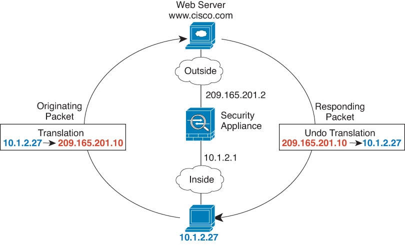
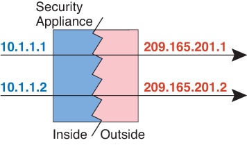
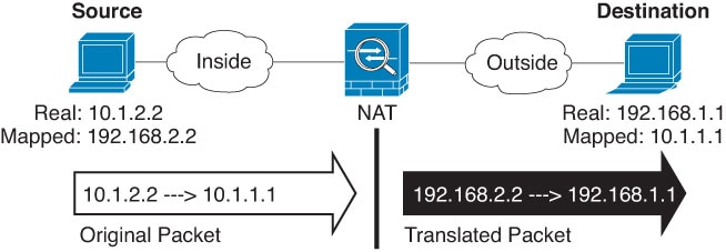
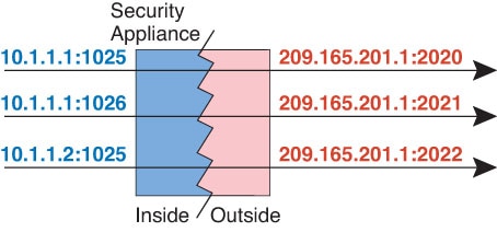
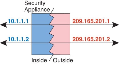
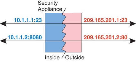
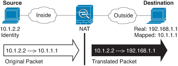
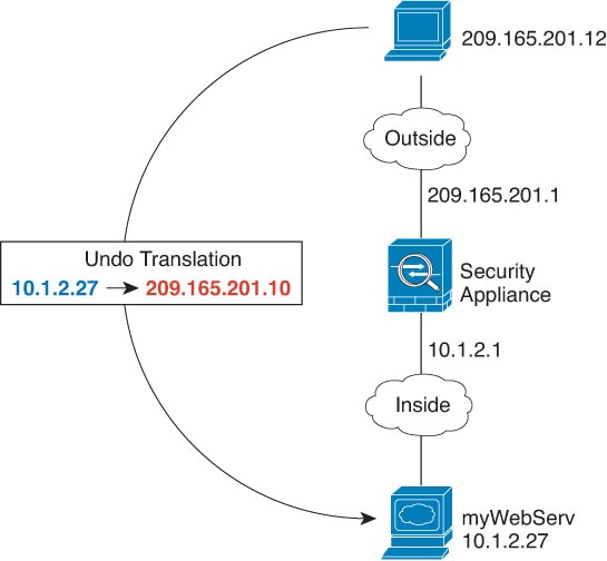
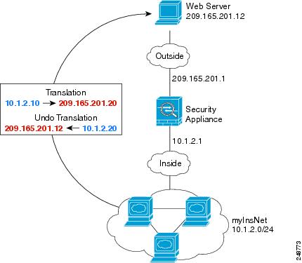
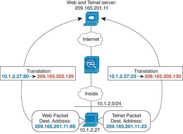
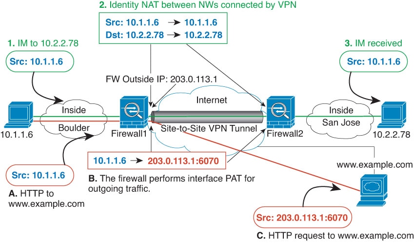
One of the main functions of NAT is to enable private IP networks to connect to the Internet. NAT replaces a private IP address with a public IP address, translating the private addresses in the internal private network into legal, routable addresses that can be used on the public Internet. In this way, NAT conserves public addresses because it can be configured to advertise at a minimum only one public address for the entire network to the outside world.

Other functions of NAT include:

  • Security—Keeping internal IP addresses hidden discourages direct attacks.

  • IP routing solutions—Overlapping IP addresses are not a problem when you use NAT.

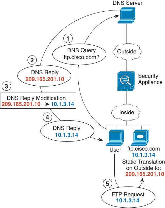
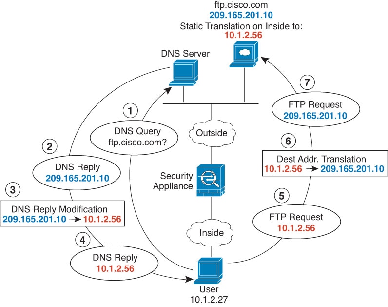
  • Flexibility—You can change internal IP addressing schemes without affecting the public addresses available externally; for example, for a server accessible to the Internet, you can maintain a fixed IP address for Internet use, but internally, you can change the server address.

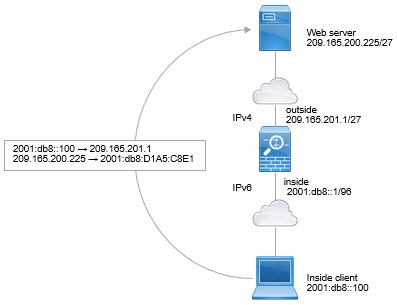
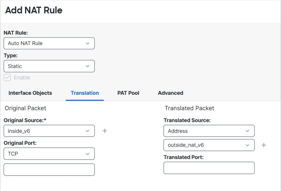
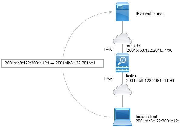
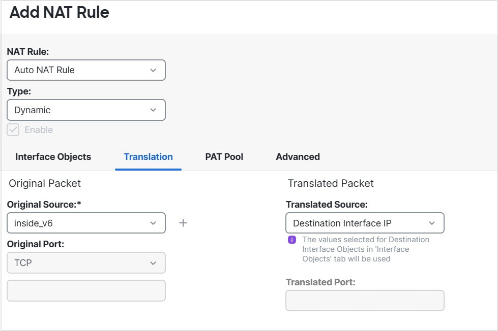
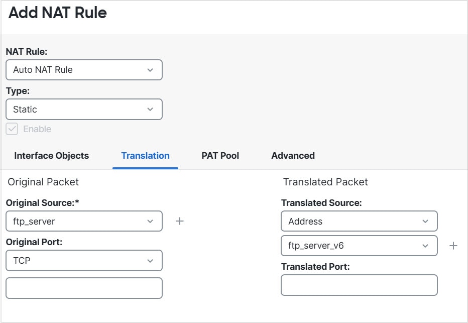
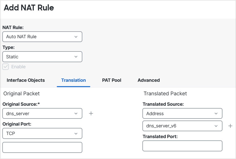
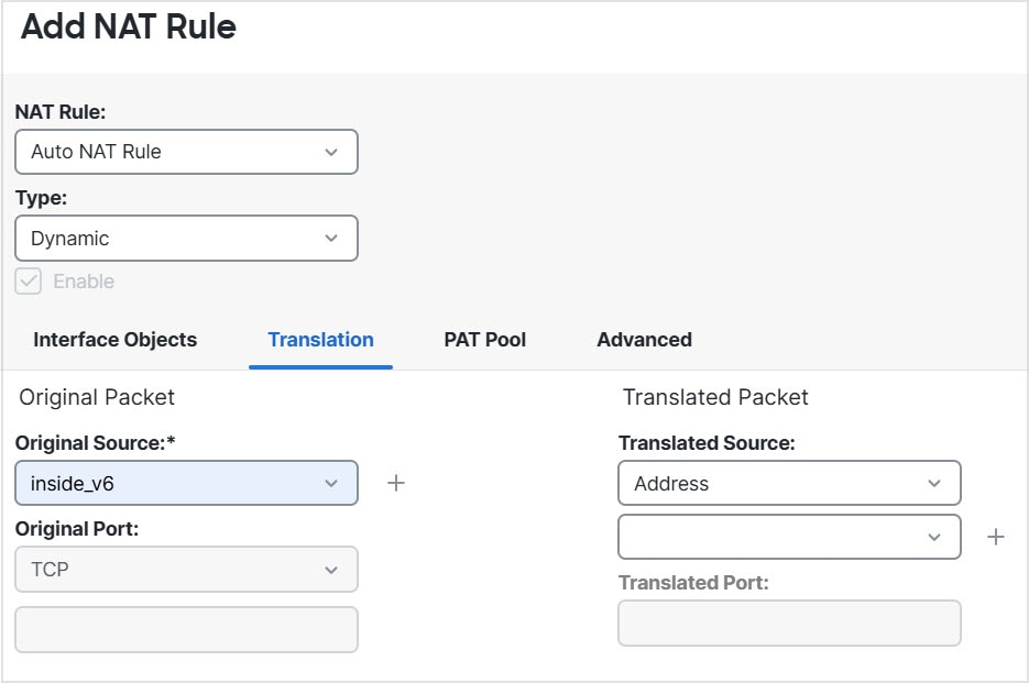
  • Translating between IPv4 and IPv6 (Routed mode only) —If you want to connect an IPv6 network to an IPv4 network, NAT lets you translate between the two types of addresses.


(注)  


NAT is not required. If you do not configure NAT for a given set of traffic, that traffic will not be translated, but will have all of the security policies applied as normal.


NAT basics

The following topics explain some of the basics of NAT.

NAT terminology

This document uses the following terminology:

  • Real address/host/network/interface—The real address is the address that is defined on the host, before it is translated. In a typical NAT scenario where you want to translate the inside network when it accesses the outside, the inside network would be the “real” network. Note that you can translate any network connected to the device, not just an inside network. Therefore if you configure NAT to translate outside addresses, “real” can refer to the outside network when it accesses the inside network.

  • Mapped address/host/network/interface—The mapped address is the address that the real address is translated to. In a typical NAT scenario where you want to translate the inside network when it accesses the outside, the outside network would be the “mapped” network.


    (注)  


    During address translation, IP addresses configured for the device interfaces are not translated.


  • Bidirectional initiation—Static NAT allows connections to be initiated bidirectionally, meaning both to the host and from the host.

  • Source and destination NAT—For any given packet, both the source and destination IP addresses are compared to the NAT rules, and one or both can be translated/untranslated. For static NAT, the rule is bidirectional, so be aware that “source” and “destination” are used in commands and descriptions throughout this guide even though a given connection might originate at the “destination” address.

NAT types

You can implement NAT using the following methods:

  • Dynamic NAT—A group of real IP addresses are mapped to a (usually smaller) group of mapped IP addresses, on a first come, first served basis. Only the real host can initiate traffic. See Dynamic NAT.

  • Dynamic Port Address Translation (PAT)—A group of real IP addresses are mapped to a single IP address using a unique source port of that IP address. See Dynamic PAT.

  • Static NAT—A consistent mapping between a real and mapped IP address. Allows bidirectional traffic initiation. See Static NAT.

  • Identity NAT—A real address is statically translated to itself, essentially bypassing NAT. You might want to configure NAT this way when you want to translate a large group of addresses, but then want to exempt a smaller subset of addresses. See Identity NAT.

NAT in routed and transparent mode

You can configure NAT in both routed and transparent firewall mode. You cannot configure NAT for interfaces operating in inline, inline tap, or passive modes. The following sections describe typical usage for each firewall mode.

NAT in routed mode

The following figure shows a typical NAT example in routed mode, with a private network on the inside.

図 1. NAT Example: Routed Mode
  1. When the inside host at 10.1.2.27 sends a packet to a web server, the real source address of the packet, 10.1.2.27, is translated to a mapped address, 209.165.201.10.

  2. When the server responds, it sends the response to the mapped address, 209.165.201.10, and the Firewall Threat Defense device receives the packet because the Firewall Threat Defense device performs proxy ARP to claim the packet.

  3. The Firewall Threat Defense device then changes the translation of the mapped address, 209.165.201.10, back to the real address, 10.1.2.27, before sending it to the host.

NAT in transparent mode or within a bridge group

Using NAT in transparent mode eliminates the need for the upstream or downstream routers to perform NAT for their networks. It can perform a similar function within a bridge group in routed mode.

NAT in transparent mode, or in routed mode between members of the same bridge group, has the following requirements and limitations:

  • You cannot configure interface PAT when the mapped address is a bridge group member interface, because there is no IP address attached to the interface.

  • ARP inspection is not supported. Moreover, if for some reason a host on one side of the Firewall Threat Defense sends an ARP request to a host on the other side of the Firewall Threat Defense, and the initiating host real address is mapped to a different address on the same subnet, then the real address remains visible in the ARP request.

  • Translating between IPv4 and IPv6 networks is not supported. Translating between two IPv6 networks, or between two IPv4 networks is supported.

The following figure shows a typical NAT scenario in transparent mode, with the same network on the inside and outside interfaces. The transparent firewall in this scenario is performing the NAT service so that the upstream router does not have to perform NAT.

図 2. NAT Example: Transparent Mode

NAT in Threat Defense transparent mode.
  1. When the inside host at 10.1.1.75 sends a packet to a web server, the real source address of the packet, 10.1.1.75, is changed to a mapped address, 209.165.201.15.

  2. When the server responds, it sends the response to the mapped address, 209.165.201.15, and the Firewall Threat Defense receives the packet because the upstream router includes this mapped network in a static route directed to the Firewall Threat Defense management IP address.

  3. The Firewall Threat Defense then undoes the translation of the mapped address, 209.165.201.15, back to the real address, 10.1.1.1.75. Because the real address is directly-connected, the Firewall Threat Defense sends it directly to the host.

  4. For host 192.168.1.2, the same process occurs, except for returning traffic, the Firewall Threat Defense looks up the route in its routing table and sends the packet to the downstream router at 10.1.1.3 based on the Firewall Threat Defense static route for 192.168.1.0/24.

Auto NAT and Manual NAT

You can implement address translation in two ways: auto NAT and manual NAT.

We recommend using auto NAT unless you need the extra features that manual NAT provides. It is easier to configure auto NAT, and it might be more reliable for applications such as Voice over IP (VoIP). (For VoIP, you might see a failure in the translation of indirect addresses that do not belong to either of the objects used in the rule.)

Auto NAT

All NAT rules that are configured as a parameter of a network object are considered to be auto NAT rules. This is a quick and easy way to configure NAT for a network object. You cannot create these rules for a group object, however.

Although these rules are configured as part of the object itself, you cannot see the NAT configuration in the object definition through the object manager.

When a packet enters an interface, both the source and destination IP addresses are checked against the auto NAT rules. The source and destination address in the packet can be translated by separate rules if separate matches are made. These rules are not tied to each other; different combinations of rules can be used depending on the traffic.

Because the rules are never paired, you cannot specify that sourceA/destinationA should have a different translation than sourceA/destinationB. Use manual NAT for that kind of functionality, where you can identify the source and destination address in a single rule.

Manual NAT

Manual NAT lets you identify both the source and destination address in a single rule. Specifying both the source and destination addresses lets you specify that sourceA/destinationA can have a different translation than sourceA/destinationB.


(注)  


For static NAT, the rule is bidirectional, so be aware that “source” and “destination” are used in commands and descriptions throughout this guide even though a given connection might originate at the “destination” address. For example, if you configure static NAT with port address translation, and specify the source address as a Telnet server, and you want all traffic going to that Telnet server to have the port translated from 2323 to 23, then you must specify the source ports to be translated (real: 23, mapped: 2323). You specify the source ports because you specified the Telnet server address as the source address.


The destination address is optional. If you specify the destination address, you can either map it to itself (identity NAT), or you can map it to a different address. The destination mapping is always a static mapping.

Comparing Auto NAT and Manual NAT

The main differences between these two NAT types are:

  • How you define the real address.

    • Auto NAT—The NAT rule becomes a parameter for a network object. The network object IP address serves as the original (real) address.

    • Manual NAT—You identify a network object or network object group for both the real and mapped addresses. In this case, NAT is not a parameter of the network object; the network object or group is a parameter of the NAT configuration. The ability to use a network object group for the real address means that manual NAT is more scalable.

  • How source and destination NAT is implemented.

    • Auto NAT— Each rule can apply to either the source or destination of a packet. So two rules might be used, one for the source IP address, and one for the destination IP address. These two rules cannot be tied together to enforce a specific translation for a source/destination combination.

    • Manual NAT—A single rule translates both the source and destination. A packet matches one rule only, and further rules are not checked. Even if you do not configure the optional destination address, a matching packet still matches one manual NAT rule only. The source and destination are tied together, so you can enforce different translations depending on the source/destination combination. For example, sourceA/destinationA can have a different translation than sourceA/destinationB.

  • Order of NAT Rules.

    • Auto NAT—Automatically ordered in the NAT table.

    • Manual NAT—Manually ordered in the NAT table (before or after auto NAT rules).

NAT rule order

Auto NAT and manual NAT rules are stored in a single table that is divided into three sections. Section 1 rules are applied first, then section 2, and finally section 3, until a match is found. For example, if a match is found in section 1, sections 2 and 3 are not evaluated. The following table shows the order of rules within each section.


(注)  


There is also a Section 0, which contains any NAT rules that the system creates for its own use. These rules have priority over all others. The system automatically creates these rules and clears xlates as needed. You cannot add, edit, or modify rules in Section 0.


表 1. NAT Rule Table

Table Section

Rule Type

Order of Rules within the Section

Section 1

Manual NAT

Applied on a first match basis, in the order they appear in the configuration. Because the first match is applied, you must ensure that specific rules come before more general rules, or the specific rules might not be applied as desired. By default, manual NAT rules are added to section 1.

By "specific rules first," we mean:

  • Static rules should come before dynamic rules.

  • Rules that include destination translation should come before rules with source translation only.

If you cannot eliminate overlapping rules, where more than one rule might apply based on the source or destination address, be especially careful to follow these recommendations.

Section 2

Auto NAT

If a match in section 1 is not found, section 2 rules are applied in the following order:

  1. Static rules.

  2. Dynamic rules.

Within each rule type, the following ordering guidelines are used:

  1. Quantity of real IP addresses—From smallest to largest. For example, an object with one address will be assessed before an object with 10 addresses.

  2. For quantities that are the same, then the IP address number is used, from lowest to highest. For example, 10.1.1.0 is assessed before 11.1.1.0.

  3. If the same IP address is used, then the name of the network object is used, in alphabetical order. For example, abracadabra is assessed before catwoman.

Section 3

Manual NAT

If a match is still not found, section 3 rules are applied on a first match basis, in the order they appear in the configuration. This section should contain your most general rules. You must also ensure that any specific rules in this section come before general rules that would otherwise apply.

For section 2 rules, for example, you have the following IP addresses defined within network objects:

  • 192.168.1.0/24 (static)

  • 192.168.1.0/24 (dynamic)

  • 10.1.1.0/24 (static)

  • 192.168.1.1/32 (static)

  • 172.16.1.0/24 (dynamic) (object def)

  • 172.16.1.0/24 (dynamic) (object abc)

The resultant ordering would be:

  • 192.168.1.1/32 (static)

  • 10.1.1.0/24 (static)

  • 192.168.1.0/24 (static)

  • 172.16.1.0/24 (dynamic) (object abc)

  • 172.16.1.0/24 (dynamic) (object def)

  • 192.168.1.0/24 (dynamic)

NAT interfaces

Except for bridge group member interfaces, you can configure a NAT rule to apply to any interface (in other words, all interfaces), or you can identify specific real and mapped interfaces. You can also specify any interface for the real address, and a specific interface for the mapped address, or vice versa.

For example, you might want to specify any interface for the real address and specify the outside interface for the mapped address if you use the same private addresses on multiple interfaces, and you want to translate them all to the same global pool when accessing the outside.

図 3. Specifying Any Interface

However, the concept of “any” interface does not apply to bridge group member interfaces. When you specify “any” interface, all bridge group member interfaces are excluded. Thus, to apply NAT to bridge group members, you must specify the member interface. This could result in many similar rules where only one interface is different. You cannot configure NAT for the Bridge Virtual Interface (BVI) itself, you can configure NAT for member interfaces only.


(注)  


You cannot configure NAT for interfaces operating in inline, inline tap, or passive modes. When specifying interfaces, you do so indirectly by selecting the interface object that contains the interface.


NAT 免除

インターネット エッジ デバイスのインターフェイスでサイト間 VPN が設定されていて、そのインターフェイス向けの NAT ルールがある場合、VPN トラフィックを NAT ルールの対象から除外する必要があります。NAT 変換の対象から VPN トラフィックを除外しない場合、トラフィックはドロップされるか、VPN トンネルを介してリモートピアにルーティングされません。

NAT 免除により、 NAT ルールによる変換対象からトラフィックを除外できます。Firewall Management Center VPN ウィザードを使用してポリシーベースのサイト間 VPN を作成する場合、[NAT免除(NAT Exempt)] オプションを選択してルールを自動的に作成できます([デバイス(Device)] > [サイト間(Site To Site)])。デフォルトで、このオプションは有効になっています。デバイスの NAT 免除は、[NATポリシー(NAT policy)] ページ([デバイス(Device)] > [NAT] > [NAT免除(NAT Exemptions)])で確認できます。

Firewall Management Center では、すべてのポリシーベースのサイト間 VPN トポロジタイプについて、NAT 免除がサポートされています。詳細については、ポリシーベースのサイト間 VPN の設定を参照してください。

サイト A とサイト B を接続するサイト間 VPN トンネルを示す次の例を考えてみます。インターネットにアクセスする必要があるトラフィックの場合、インターネットにアクセスするために、NAT によってプライベート IP がパブリック IP アドレスに変換されます。VPN トンネルを通過する必要があるトラフィックについては、VPN ウィザードでデバイスの NAT 免除を設定する必要があります。

図 4. NAT 免除を使用したサイト間 VPN トポロジ

7.4 より前のバージョンからアップグレードする際に NAT 免除を有効にしていると、Firewall Management Center はこのオプションを無効にすることに注意してください。ポリシーベースのサイト間 VPN ウィザードでこのオプションを有効にする必要があります。

NAT 用のルーティングの設定

Firewall Threat Defense デバイスは、変換された(マッピング)アドレスに送信されるパケットの宛先である必要があります。

パケットを送信する際、デバイスは宛先インターフェイスを使用するか(指定した場合)、またはルーティング テーブル ルックアップ(指定しない場合)を使用して、出力インターフェイスを決定します。アイデンティティ NAT の場合は、宛先インターフェイスを指定した場合でもルート ルックアップを使用することができます。

以下で説明するように、必要なルーティング設定はマッピング アドレスによって異なります。

Addresses on the same network as the mapped interface

If you use addresses on the same network as the destination (mapped) interface, the Firewall Threat Defense device uses proxy ARP to answer any ARP requests for the mapped addresses, thus intercepting traffic destined for a mapped address. This solution simplifies routing because the Firewall Threat Defense device does not have to be the gateway for any additional networks. This solution is ideal if the outside network contains an adequate number of free addresses, a consideration if you are using a 1:1 translation like dynamic NAT or static NAT. Dynamic PAT greatly extends the number of translations you can use with a small number of addresses, so even if the available addresses on the outside network is small, this method can be used. For PAT, you can even use the IP address of the mapped interface.


(注)  


If you configure the mapped interface to be any interface, and you specify a mapped address on the same network as one of the mapped interfaces, then if an ARP request for that mapped address comes in on a different interface, then you need to manually configure an ARP entry for that network on the ingress interface, specifying its MAC address. Typically, if you specify any interface for the mapped interface, then you use a unique network for the mapped addresses, so this situation would not occur. Configure the ARP table in the ingress interface's Advanced settings.


Addresses on a unique network

If you need more addresses than are available on the destination (mapped) interface network, you can identify addresses on a different subnet. The upstream router needs a static route for the mapped addresses that points to the Firewall Threat Defense device.

Alternatively for routed mode, you can configure a static route on the Firewall Threat Defense device for the mapped addresses using any IP address on the destination network as the gateway, and then redistribute the route using your routing protocol. For example, if you use NAT for the inside network (10.1.1.0/24) and use the mapped IP address 209.165.201.5, then you can configure a static route for 209.165.201.5 255.255.255.255 (host address) to the 10.1.1.99 gateway that can be redistributed.

For transparent mode, if the real host is directly-connected, configure the static route on the upstream router to point to the Firewall Threat Defense device: specify the bridge group IP address. For remote hosts in transparent mode, in the static route on the upstream router, you can alternatively specify the downstream router IP address.

The same address as the real address (identity NAT)

The default behavior for identity NAT has proxy ARP enabled, matching other static NAT rules. You can disable proxy ARP if desired. You can also disable proxy ARP for regular static NAT if desired, in which case you need to be sure to have proper routes on the upstream router.

Normally for identity NAT, proxy ARP is not required, and in some cases can cause connectivity issues. For example, if you configure a broad identity NAT rule for “any” IP address, then leaving proxy ARP enabled can cause problems for hosts on the network directly connected to the mapped interface. In this case, when a host on the mapped network wants to communicate with another host on the same network, then the address in the ARP request matches the NAT rule (which matches “any” address). The Firewall Threat Defense device will then proxy ARP for the address, even though the packet is not actually destined for the Firewall Threat Defense device. (Note that this problem occurs even if you have a manual NAT rule; although the NAT rule must match both the source and destination addresses, the proxy ARP decision is made only on the “source” address). If the Firewall Threat Defense device ARP response is received before the actual host ARP response, then traffic will be mistakenly sent to the Firewall Threat Defense device.

NAT ポリシーの要件と前提条件

Supported domains

Any

User roles

Admin

Access Admin

Network Admin

Guidelines for NAT

The following topics provide detailed guidelines for implementing NAT.

Firewall mode guidelines for NAT

NAT is supported in routed and transparent firewall mode.

However, configuring NAT on bridge group member interfaces (interfaces that are part of a Bridge Group Virtual Interface, or BVI) has the following restrictions:

  • When configuring NAT for the members of a bridge group, you specify the member interface. You cannot configure NAT for the bridge group interface (BVI) itself.

  • When doing NAT between bridge group member interfaces, you must specify the real and mapped addresses. You cannot specify “any” as the interface.

  • You cannot configure interface PAT when the mapped address is a bridge group member interface, because there is no IP address attached to the interface.

  • You cannot translate between IPv4 and IPv6 networks (NAT64/46) when the source and destination interfaces are members of the same bridge group. Static NAT/PAT 44/66, dynamic NAT44/66, and dynamic PAT44 are the only allowed methods; dynamic PAT66 is not supported. However, you can do NAT64/46 between members of different bridge groups, or between a bridge group member (source) and standard routed interface (destination).


(注)  


You cannot configure NAT for interfaces operating in inline, inline tap, or passive modes.


IPv6 NAT guidelines

NAT supports IPv6 with the following guidelines and restrictions.

  • For standard routed mode interfaces, you can also translate between IPv4 and IPv6.

  • You cannot translate between IPv4 and IPv6 for interfaces that are members of the same bridge group. You can translate between two IPv6 or two IPv4 networks only. This restriction does not apply when the interfaces are members of different bridge groups, or between a bridge group member and a standard routed interface.

  • You cannot use dynamic PAT for IPv6 (NAT66) when translating between interfaces in the same bridge group. This restriction does not apply when the interfaces are members of different bridge groups, or between a bridge group member and a standard routed interface.

  • For static NAT, you can specify an IPv6 subnet up to /64. Larger subnets are not supported.

  • When using FTP with NAT46, when an IPv4 FTP client connects to an IPv6 FTP server, the client must use either the extended passive mode (EPSV) or extended port mode (EPRT); PASV and PORT commands are not supported with IPv6.

IPv6 NAT best practices

You can use NAT to translate between IPv6 networks, and also to translate between IPv4 and IPv6 networks (routed mode only). We recommend the following best practices:

  • NAT66 (IPv6-to-IPv6)—We recommend using static NAT. Although you can use dynamic NAT or PAT, IPv6 addresses are in such large supply, you do not have to use dynamic NAT. If you do not want to allow returning traffic, you can make the static NAT rule unidirectional (manual NAT only).

  • NAT46 (IPv4-to-IPv6)—We recommend using static NAT. Because the IPv6 address space is so much larger than the IPv4 address space, you can easily accommodate a static translation. If you do not want to allow returning traffic, you can make the static NAT rule unidirectional (manual NAT only). When translating to an IPv6 subnet (/96 or lower), the resulting mapped address is by default an IPv4-embedded IPv6 address, where the 32-bits of the IPv4 address is embedded after the IPv6 prefix. For example, if the IPv6 prefix is a /96 prefix, then the IPv4 address is appended in the last 32-bits of the address. For example, if you map 192.168.1.0/24 to 201b::0/96, then 192.168.1.4 will be mapped to 201b::0.192.168.1.4 (shown with mixed notation). If the prefix is smaller, such as /64, then the IPv4 address is appended after the prefix, and a suffix of 0s is appended after the IPv4 address. You can also optionally translate the addresses net-to-net, where the first IPv4 address maps to the first IPv6 address, the second to the second, and so on.

  • NAT64 (IPv6-to-IPv4)—You may not have enough IPv4 addresses to accommodate the number of IPv6 addresses. We recommend using a dynamic PAT pool to provide a large number of IPv4 translations.

検査対象プロトコルの NAT サポート

セカンダリ接続を開いたり、パケットに IP アドレスを埋め込んだりする、一部のアプリケーション層プロトコルは、次のサービスを提供するために検査されます。

  • ピンホール作成:一部のアプリケーション プロトコルは標準ポートまたはネゴシエート ポートのどちらかでセカンダリ TCP または UDP 接続を開きます。検査により、これらのセカンダリ ポートに対してピンホールが開かれるため、アクセス制御ルールを作成する必要はありません。

  • NAT リライト:FTP などのプロトコルは、セカンダリ接続用の IP アドレスとポートをプロトコルの一部としてパケット データに埋め込みます。いずれかのエンドポイントに対して NAT 変換が含まれている場合、インスペクション エンジンはパケット データを書き換えて、埋め込まれたアドレスとポートの NAT 変換を反映させます。NAT リライトなしでは、セカンダリ接続は機能しません。

  • プロトコル強制:一部の検査は、検査対象プロトコルの RFC に対して一定の準拠を強制します。

次の表は、NAT リライトが適用される検査対象プロトコルとそれらの NAT 制限を示します。これらのプロトコルを含む NAT ルールを作成する場合は、これらの制限に留意してください。ここに示されていない検査対象プロトコルには NAT リライトが適用されません。こうしたインスペクションには GTP、HTTP、IMAP、POP、SMTP、SSH および SSL があります。


(注)  


NAT リライトは示されているポートでのみサポートされます。これらのプロトコルの一部に対して、ネットワーク分析ポリシーを使用して検査を他のポートに拡張できますが、NAT リライトはそれらのポートに拡張されません。これには、DCERPC、DNS、FTP、および Sun RPC インスペクションが含まれます。これらのプロトコルを非標準ポートで使用する場合、接続で NAT を使用しないでください。


表 2. NAT がサポートするアプリケーション インスペクション

アプリケーション

検査対象のプロトコル、ポート

NAT の制限

ピンホールの作成

DCERPC

TCP/135

NAT64 はサポートされません。

はい

DNS over UDP

UDP/53

NAT サポートは、WINS 経由の名前解決では使用できません。

いいえ

ESMTP

TCP/25

NAT64 はサポートされません。

いいえ

FTP

TCP/21

(クラスタリング)スタティック PAT はサポートされません。

H.323 H.225(発呼信号)

H.323 RAS

TCP/1720

UDP/1718

RAS の場合、UDP/1718 ~ 1719

(クラスタリング)スタティック PAT はサポートされません。

拡張 PAT はサポートされません。

NAT64 はサポートされません。

はい

ICMP

ICMP Error

ICMP

(デバイス インターフェイスに転送される ICMP トラフィックは検査されません)

制限なし。

いいえ

IP オプション

RSVP

NAT64 はサポートされません。

いいえ

NetBIOS Name Server over IP

UDP/137、138(送信元ポート)

拡張 PAT はサポートされません。

NAT64 はサポートされません。

いいえ

RSH

TCP/514

PAT はサポートされません。

NAT64 はサポートされません。

(クラスタリング)スタティック PAT はサポートされません。

RTSP

TCP/554

(HTTP クローキングは処理されません)

拡張 PAT はサポートされません。

NAT64 はサポートされません。

(クラスタリング)スタティック PAT はサポートされません。

SIP

TCP/5060


UDP/5060

拡張 PAT はサポートされません。

NAT64 または NAT46 はなし。

(クラスタリング)スタティック PAT はサポートされません。

Skinny(SCCP)

TCP/2000

拡張 PAT はサポートされません。

NAT64、NAT46、または NAT66 はなし。

(クラスタリング)スタティック PAT はサポートされません。

SQL*Net

(バージョン 1 および 2)

TCP/1521

拡張 PAT はサポートされません。

NAT64 はサポートされません。

(クラスタリング)スタティック PAT はサポートされません。

Sun RPC

TCP/111

UDP/111

拡張 PAT はサポートされません。

NAT64 はサポートされません。

はい

TFTP

UDP/69

NAT64 はサポートされません。

(クラスタリング)スタティック PAT はサポートされません。

ペイロード IP アドレスは変換されません。

はい

XDMCP

UDP/177

拡張 PAT はサポートされません。

NAT64 はサポートされません。

(クラスタリング)スタティック PAT はサポートされません。

はい

FQDN destination guidelines

You can specify the translated (mapped) destination in a manual NAT rule using a fully-qualified domain name (FQDN) network object instead of an IP address. For example, you can create a rule based on traffic that is destined for the www.example.com web server.

When using an FQDN, the system obtains the DNS resolution and writes the NAT rule based on the returned address. If you are using multiple DNS server groups, the filter domains are honored and the address is requested from the appropriate group based on the filters. If more than one address is obtained from the DNS server, the address used is based on the following:

  • If there is an address on the same subnet as the specified interface, that address is used. If there isn’t one on the same subnet, the first address returned is used.

  • The IP type for the translated source and translated destination must match. For example, if the translated source address is IPv6, the FQDN object must specify IPv6 as the address type. If the translated source is IPv4, the FQDN object can specify IPv4 or both IPv4 and IPv6. In this case, an IPv4 address is selected.

You cannot include an FQDN object in a network group that is used for manual NAT destination. In NAT, an FQDN object must be used alone, as only a single destination host makes sense for this type of NAT rule.

If the FQDN cannot be resolved to an IP address, the rule is not functional until a DNS resolution is obtained.

Additional guidelines for NAT

  • NAT rules apply to through the device traffic only, they do not apply to traffic initiated by the device, such as a RADIUS authentication.

  • For interfaces that are members of a bridge group, you write NAT rules for the member interfaces. You cannot write NAT rules for the Bridge Virtual Interface (BVI) itself.

  • You cannot write NAT rules for a Virtual Tunnel Interface (VTI), which are used in site-to-site VPN. Writing rules for the VTI's source interface will not apply NAT to the VPN tunnel. To write NAT rules that will apply to VPN traffic tunneled on a VTI, you must use "any" as the interface; you cannot explicitly specify interface names.

  • (Auto NAT only.) You can only define a single NAT rule for a given object; if you want to configure multiple NAT rules for an object, you need to create multiple objects with different names that specify the same IP address.

  • If a VPN is defined on an interface, inbound ESP traffic on the interface is not subject to the NAT rules. The system allows the ESP traffic for established VPN tunnels only, dropping traffic not associated with an existing tunnel. This restriction applies to ESP and UDP ports 500 and 4500.

  • If you define a site-to-site VPN on a device that is behind a device that is applying dynamic PAT, so that UDP ports 500 and 4500 are not the ones actually used, you must initiate the connection from the device that is behind the PAT device. The responder cannot initiate the security association (SA) because it does not know the correct port numbers.

  • If you change the NAT configuration, and you do not want to wait for existing translations to time out before the new NAT configuration is used, you can clear the translation table using the clear xlate command in the device CLI. However, clearing the translation table disconnects all current connections that use translations.

    If you create a new NAT rule that should apply to an existing connection (such as a VPN tunnel), you need to use clear conn to end the connection. Then, the attempt to re-establish the connection should hit the NAT rule and the connection should be NAT'ed correctly.


    (注)  


    If you remove a dynamic NAT or PAT rule, and then add a new rule with mapped addresses that overlap the addresses in the removed rule, then the new rule will not be used until all connections associated with the removed rule time out or are cleared using the clear xlate or clear conn commands. This safeguard ensures that the same address is not assigned to multiple hosts.


  • You cannot use an object group with both IPv4 and IPv6 addresses; the object group must include only one type of address.

  • A network object used in NAT cannot include more than 131,838 IP addresses, either explicitly or implied in a range of addresses or a subnet. Break up the address space into smaller ranges and write separate rules for the smaller objects.

  • (Manual NAT only.) When using any as the source address in a NAT rule, the definition of “any” traffic (IPv4 vs. IPv6) depends on the rule. Before the Firewall Threat Defense device performs NAT on a packet, the packet must be IPv6-to-IPv6 or IPv4-to-IPv4; with this prerequisite, the Firewall Threat Defense device can determine the value of any in a NAT rule. For example, if you configure a rule from “any” to an IPv6 server, and that server was mapped from an IPv4 address, then any means “any IPv6 traffic.” If you configure a rule from “any” to “any,” and you map the source to the interface IPv4 address, then any means “any IPv4 traffic” because the mapped interface address implies that the destination is also IPv4.

  • You can use the same mapped object or group in multiple NAT rules.

  • The mapped IP address pool cannot include:

    • The mapped interface IP address. If you specify “any” interface for the rule, then all interface IP addresses are disallowed. For interface PAT (routed mode only), specify the interface name instead of the interface address.

    • The failover interface IP address.

    • (Transparent mode.) The management IP address.

    • (Dynamic NAT.) The standby interface IP address when VPN is enabled.

  • Avoid using overlapping addresses in static and dynamic NAT policies. For example, with overlapping addresses, a PPTP connection can fail to get established if the secondary connection for PPTP hits the static instead of dynamic xlate.

  • You cannot use overlapping addresses in the source address of a NAT rule and a remote access VPN address pool.

  • If you specify a destination interface in a rule, then that interface is used as the egress interface rather than looking up the route in the routing table. However, for identity NAT, you have the option to use a route lookup instead.

  • If you use PAT on Sun RPC traffic, which is used to connect to NFS servers, be aware that the NFS server might reject connections if the PAT'ed port is above 1024. The default configuration of NFS servers is to reject connections from ports higher than 1024. The error is typically "Permission Denied." Mapping ports above 1024 happens if you do not select the option to include the reserved ports (1-1023) in the port range of a PAT pool. You can avoid this problem by changing the NFS server configuration to allow all port numbers.

  • NAT applies to through traffic only. Traffic generated by the system is not subject to NAT.

  • Do not name a network object or group pat-pool, using any combination of upper- or lower-case letters.

  • The unidirectional option is mainly useful for testing purposes and might not work with all protocols. For example, SIP requires protocol inspection to translate SIP headers using NAT, but this will not occur if you make the translation unidirectional.

  • You cannot use NAT on the internal payload of Protocol Independent Multicast (PIM) registers.

  • (Manual NAT) When writing NAT rules for a dual ISP interface setup (primary and backup interfaces using service level agreements in the routing configuration), do not specify destination criteria in the rule. Ensure the rule for the primary interface comes before the rule for the backup interface. This allows the device to choose the correct NAT destination interface based on the current routing state when the primary ISP is unavailable. If you specify destination objects, the NAT rule will always select the primary interface for the otherwise duplicate rules.

  • If you get the ASP drop reason nat-no-xlate-to-pat-pool for traffic that should not match the NAT rules defined for the interface, configure identity NAT rules for the affected traffic so the traffic can pass untranslated.

  • If you configure NAT for GRE tunnel endpoints, you must disable keepalives on the endpoints or the tunnel cannot be established. The endpoints send keepalives to the original addresses.

  • DHCP and BOOTP share ports UDP/67-68. Because BOOTP is obsolete, writing NAT rules for the bootps port can cause port allocation problems when also running DHCP. Consider using DHCP relay instead for transmitting DHCP requests between network segments.

  • In rare cases, return traffic (server to client) with an existing translation (xlate) might be logged as a new flow in Connection Events. This can occur when the client has already terminated the connection and the server sends another packet that reaches the device during the brief interval between connection closure and xlate removal, often due to application behavior or TCP stack cleanup. Because the device removes the xlate only after deleting the connection, a server packet can arrive while the xlate still exists. If no valid connection entry is found, the device logs a separate connection event based on the matched Access Control Policy rule.

NAT ポリシーの管理

ネットワークアドレス変換(NAT)では、着信パケットの IP アドレスが発信パケットの別のアドレスに変換されます。NAT の主な機能の 1 つは、プライベート IP ネットワークがインターネットに接続できるようにすることです。NAT では、プライベート IP アドレスがパブリック IP に置き換えられ、内部プライベートネットワーク内のプライベートアドレスがパブリックインターネットで使用可能でルーティング可能なアドレスに変換されます。NAT では、xlate とも呼ばれる変換が追跡され、リターントラフィックが正しい未変換のホストアドレスに確実に送信されます。

手順


ステップ 1

Devices > NATを選択します。

ステップ 2

NAT ポリシーを管理します。

  • [作成(Create)]:[新しいポリシー(New Policy)] をクリックして、[Threat Defense NAT] を選択します。NAT ポリシーの作成を参照してください。

  • [コピー(Copy)]:コピーするポリシーの横にある Copy (copy icon) をクリックします。コピーに新しい一意の名前を付けるように求められます。コピーには、すべてのポリシールールと設定が含まれますが、デバイスの割り当ては含まれません。

  • [レポート(Report)]:ポリシーの Report (Report icon) をクリックします。ポリシー属性、デバイスの割り当て、ルール、およびオブジェクト使用情報を含む PDF レポートを保存するように求められます。

  • [編集(Edit)]:編集するポリシーの横にある Edit (edit icon) をクリックします。脅威に対する防御のための NAT の設定を参照してください。

  • [削除(Delete)]: 削除するポリシーの横にある Delete (delete icon) をクリックして、[OK] をクリックします。続行するかどうかを尋ねるプロンプトで、ポリシー内に別のユーザーの未保存の変更が存在するかどうかも通知されます。

    注意    


    管理対象デバイスに NAT ポリシーを展開した後は、デバイスからそのポリシーを削除できません。その代わりに、ルールを持たない NAT ポリシーを展開して、すでに管理対象デバイスに存在する NAT ルールを削除する必要があります。また、どのターゲット デバイスでも、最後に展開したポリシーは期限切れであっても削除できません。ポリシーを完全に削除する前に、それらのターゲットに異なるポリシーを展開する必要があります。


NAT ポリシーの作成

新しい NAT ポリシーを作成する場合、少なくとも一意の名前を付ける必要があります。ポリシーの作成時にポリシー ターゲットを特定する必要はありませんが、ポリシーを展開する前に、この手順を実行する必要があります。ルールを持たない NAT ポリシーをデバイスに適用すると、そのデバイスからすべての NAT ルールが削除されます。

手順


ステップ 1

Devices > NATを選択します。

ステップ 2

[新しいポリシー(New Policy)] をクリックし、ドロップダウンリストで、Firewall Threat Defense デバイスの [Threat Defense NAT] を選択します。

ステップ 3

[名前(Name)] に一意の名前を入力します。

ステップ 4

必要に応じて、[説明(Description)] を入力します。

ステップ 5

ポリシーを展開するデバイスを選択します。

  • [使用可能なデバイス(Available Devices)] リストでデバイスを選択し、[ポリシーに追加(Add to Policy)] をクリックします。
  • [使用可能なデバイス(Available Devices)] リストから [選択されたデバイス(Selected Devices)] リストに、デバイスをクリックしてドラッグします。
  • デバイスの横にあるDelete (delete icon)をクリックして、[選択されたデバイス(Selected Devices)] リストからデバイスを削除します。

ステップ 6

[保存(Save)] をクリックします。


NAT ポリシーの対象の設定

ポリシーを適用する管理対象デバイスは、ポリシーを作成または編集する際に特定できます。使用可能なデバイスおよび高可用性ペアのリストを検索して、選択したデバイスのリストに追加できます。

手順


ステップ 1

Devices > NAT を選択します。

ステップ 2

変更する NAT ポリシーの横にある Edit (edit icon) をクリックします。

代わりに View (View button) 表示される場合、設定は先祖ドメインに属しており、設定を変更する権限がありません。

ステップ 3

[ポリシー割り当て(Policy Assignments)] をクリックします。

ステップ 4

次のいずれかを実行します。

  • デバイス、高可用性ペア、またはデバイスグループをポリシーに割り当てるには、[使用可能なデバイス(Available Devices)] リストで選択し、[ポリシーに追加(Add to Policy)] をクリックします。ドラッグ アンド ドロップを使用することもできます。
  • デバイスの割り当てを削除するには、[選択されたデバイス(Selected Devices)] リストのデバイス、高可用性ペア、またはデバイスグループの横にある Delete (delete icon) をクリックします。

ステップ 5

[OK] をクリックします。


脅威に対する防御のための NAT の設定

ネットワーク アドレス変換は非常に複雑になることがあります。変換の問題が発生したり、トラブルシューティングが難しい状況にならないよう、ルールはできるだけ単純にすることを推奨します。NAT を実装する前に、慎重に計画を立てることが非常に重要です。以下の手順では、基本的なアプローチを説明します。

NAT ポリシーは、共有ポリシーです。同様の NAT ルールを持つべきデバイスに、ポリシーを割り当てます。

割り当てられたデバイスにポリシーの特定のルールが適用されるかどうかは、ルールで使用されるインターフェイス オブジェクト(セキュリティ ゾーンまたはインターフェイス グループ)によって決定されます。インターフェイス オブジェクトにデバイスのインターフェイスが 1 つ以上含まれている場合、ルールがデバイスに導入されます。したがって、注意深くインターフェイス オブジェクトを設計することで、単一の共有ポリシー内のデバイスのサブセットに適用されるルールを設定できます。「任意」のインターフェイス オブジェクトに適用されるルールは、すべてのデバイスに導入されます。

インターフェイスのタイプを、そのインターフェイスがあるデバイスを対象とする NAT ポリシーでの使用が無効なタイプに変更した場合、ポリシーはそのインターフェイスに削除済みのラベルを付けます。NAT ポリシーの [保存(Save)] をクリックすると、インターフェイスはポリシーから自動的に削除されます。

デバイスのグループにさまざまなルールが必要な場合は、複数の NAT ポリシーを設定できます。

手順


ステップ 1

[デバイス(Devices)] > [NAT] を選択します。

  • 新しいポリシーを作成するには、[新しいポリシー(New Policy)]をクリックします。ポリシーに名前を付け、オプションでデバイスを割り当て、[保存(Save)] をクリックします。

    デバイスの割り当てを後で変更するには、ポリシーを編集して、[ポリシー割り当て(Policy Assignments)] をクリックします。

  • 既存の Threat Defense NAT ポリシーを編集するには、Edit (edit icon)をクリックします。

    代わりに View (View button) 表示される場合、設定は先祖ドメインに属しており、設定を変更する権限がありません。

ステップ 2

必要となるルールのタイプを決定します。

作成できるルールには、ダイナミック NAT ルール、ダイナミック PAT ルール、スタティック NAT ルール、およびアイデンティティ NAT ルールがあります。概要については、NAT typesを参照してください。

ステップ 3

手動 NAT または自動 NAT として実装するルールを決定します。

この 2 つの実装オプションの比較については、Auto NAT and Manual NATを参照してください。

ステップ 4

デバイスごとにカスタマイズするルールを決定します。

複数のデバイスに 1 つの NAT ポリシーを割り当てることができるため、多くのデバイスに 1 つのルールを設定できます。ただし、各デバイスによって異なる解釈が必要なルールや、デバイスのサブセットにのみ適用すべきルールの場合もあります。

インターフェイス オブジェクトを使用して、ルールを設定するデバイスを制御します。次に、ネットワーク オブジェクトでオブジェクトのオーバーライドを使用して、デバイスごとに使用されるアドレスをカスタマイズします。

詳細については、複数のデバイスの NAT ルールのカスタマイズを参照してください。

ステップ 5

以下の項で説明している手順に従ってルールを作成します。

ステップ 6

NAT ポリシーおよびルールを管理します。

以下の操作によって、ポリシーとそのルールを管理できます。

  • ポリシーの名前または説明を編集するには、これらのフィールドをクリックし、変更を入力して、フィールドの外側をクリックします。

  • 特定のデバイスに適用されるルールのみを表示するには、[デバイスによるフィルタ(Filter by Device)] をクリックし、目的のデバイスを選択します。ルールがデバイスのインターフェイスを含むインターフェイス オブジェクトを使用している場合、そのデバイスにルールが適用されます。

  • ポリシーの警告またはエラーを表示するには、[Show warnings] をクリックして、[Device] を選択します。警告とエラーによって、トラフィックフローに悪影響を及ぼしたり、ポリシーの展開を妨げたりする構成がマークされます。

  • ポリシーが割り当てられているデバイスを変更するには、[ポリシー割り当て(Policy Assignments)] リンクをクリックし、必要に応じて選択したデバイス リストを変更します。

  • ルールが有効であるか、または無効であるかを変更するには、ルールを右クリックし、[状態(State)] コマンドから目的のオプションを選択します。これらのコントロールを使用して、ルールを削除しないで一時的に無効にすることができます。

  • ルールを追加するには、[ルールの追加(Add Rule)] ボタンをクリックします。

  • ルールを編集するには、ルールのEdit (edit icon)をクリックします。

  • ルールを削除するには、ルールのDelete (delete icon)をクリックします。

  • ページに表示するルールの数を変更するには、[Rows Per Page] ドロップダウンリストを使用します。

  • 有効化、無効化、または削除する複数のルールを選択するには、各ルールのチェックボックスまたはヘッダーのチェックボックスをクリックしてから、アクションを実行します。

ステップ 7

[Save(保存)] をクリックします。

これで、Deploy > Deploy に移動して、ポリシーを割り当てたデバイスにデプロイします。変更内容は導入するまで適用されません。


複数のデバイスの NAT ルールのカスタマイズ

NAT ポリシーは共有されるため、複数のデバイスに特定のポリシーを割り当てることができます。ただし、指定したオブジェクトに設定できる自動 NAT ルールは 1 つまでです。そのため、変換を実行する特定のデバイスに基づいてオブジェクトにさまざまな変換を設定する場合は、インターフェイス オブジェクト(セキュリティ ゾーンまたはインターフェイス グループ)を注意深く設定し、変換済みアドレスのネットワーク オブジェクトのオーバーライドを定義する必要があります。

インターフェイス オブジェクトでは、ルールを設定するデバイスを決定します。ネットワーク オブジェクトのオーバーライドでは、そのオブジェクトの特定のデバイスで使用する IP アドレスを決定します。

次のような例が考えられます。

  • FTD-A と FTD-B に、「inside」という名前のインターフェイスに接続される内部ネットワーク 192.168.1.0/24 があります。

  • FTD-A では、「外部」インターフェイスに移動するときに、すべての 192.168.1.0/24 アドレスを 10.100.10.10 ~ 10.100.10.200 の範囲の NAT プールに変換する必要があります。

  • FTD-B では、「外部」インターフェイスに移動するときに、すべての 192.168.1.0/24 アドレスを 10.200.10.10 ~ 10.200.10.200 の範囲の NAT プールに変換する必要があります。

このように変換するには、次の手順を実行します。この例のルールはダイナミック自動 NAT 用ですが、任意のタイプの NAT ルールにこのテクニックを一般化できます。

手順


ステップ 1

内部インターフェイスと外部インターフェイスのセキュリティ ゾーンを作成します。

  1. [オブジェクト(Objects)] > [オブジェクト管理(Object Management)] を選択します。

  2. コンテンツのテーブルから [インターフェイス オブジェクト(Interface Objects)] を選択し、[追加(Add)] > [セキュリティ ゾーン(Security Zone)] をクリックします。(ゾーンの代わりにインターフェイス グループを使用できます)。

  3. 内部ゾーンのプロパティを設定します。

    • [名前(Name)]:inside-zone などの名前を入力します。

    • [タイプ(Type)]:ルーテッド モードのデバイスの場合は [ルーテッド(Routed)]、トランスペアレント モードの場合は [スイッチド(Switched)] を選択します。

    • [選択したインターフェイス(Selected Interfaces)]:選択済みリストに FTD-A/内部および FTD-B/内部インターフェイスを追加します。

  4. [保存(Save)] をクリックします。

  5. [追加(Add)] > [セキュリティ ゾーン(Security Zone)] をクリックし、外部ゾーンのプロパティを定義します。

    • [名前(Name)]:outside-zone などの名前を入力します。

    • [インターフェイスタイプ(Interface Type)]:ルーテッドモードのデバイスの場合は [ルーテッド(Routed)]、トランスペアレントモードの場合は [スイッチド(Switched)] を選択します。

    • [選択したインターフェイス(Selected Interfaces)]:選択済みリストに FTD-A/外部および FTD-B/外部インターフェイスを追加します。

  6. [保存(Save)] をクリックします。

ステップ 2

[オブジェクト管理(Object Management)] ページで、元の内部ネットワーク内のネットワーク オブジェクトを作成します。

  1. コンテンツのテーブルから [ネットワーク(Network)] を選択し、[ネットワークの追加(Add Network)] > [Add Object(オブジェクトの追加)] をクリックします。

  2. 内部ネットワークのプロパティを設定します。

    • [名前(Name)]:inside-network などの名前を入力します。

    • [ネットワーク(Network)]:192.168.1.0/24 などのネットワーク アドレスを入力します。

  3. [保存(Save)] をクリックします。

ステップ 3

変換済み NAT プールのネットワーク オブジェクトを作成し、オーバーライドを定義します。

  1. [ネットワークの追加(Add Network)] > [Add Object(オブジェクトの追加)] をクリックします。

  2. FTD-A の NAT プールのプロパティを設定します。

    • [名前(Name)]:NAT-pool などの名前を入力します。

    • [ネットワーク(Network)]:10.100.10.10-10.100.10.200 などの FTD-A のプールに含めるアドレスの範囲を入力します。

  3. [オーバーライドを許可(Allow Overrides)] を選択します。

  4. [オーバーライド(Override)] の見出しをクリックして、オブジェクト オーバーライドのリストを開きます。

  5. [追加(Add)] をクリックして、[オブジェクト オーバーライドの追加(Add Object Override)] ダイアログボックスを開きます。

  6. FTD-B を選択し、[選択されたデバイス(Selected Devices)] リストに追加します。

  7. [オーバーライド(Override)] をクリックし、[ネットワーク(Network)] を [10.200.10.10-10.200.10.200] に変更します

  8. [追加(Add)] をクリックして、オーバーライドをデバイスに追加します。

    FTD-B のオーバーライドを定義すると、FTD-B のこのオブジェクトが設定されるたびに、元のオブジェクトに定義されている値の代わりにオーバーライド値が使用されます。

  9. [保存(Save)] をクリックします。

ステップ 4

NAT ルールを設定します。

  1. [Devices > NAT] を選択し、Firewall Threat Defense NAT ポリシーを作成するか、編集します。

  2. [ルールの追加(Add Rule)] をクリックします。

  3. 次のプロパティを設定します。

    • [NAT ルール(NAT Rule)] = 自動 NAT ルール。

    • [タイプ(Type)] = Dynamic。

  4. [インターフェイスオブジェクト(Interface Objects)] で、次の項目を設定します。

    • [送信元インターフェイス オブジェクト(Source Interface Objects)]:inside-zone。

    • [宛先インターフェイス オブジェクト(Destination Interface Objects)]:outside-zone。

    (注)  


    インターフェイス オブジェクトはルールが設定されるデバイスを制御します。この例ではゾーンに FTD-A と FTD-B のインターフェイスのみが含まれているため、NAT ポリシーが追加のデバイスに割り当てられた場合でも、ルールはこれらの 2 つのデバイスにのみ展開されます。

  5. [変換(Translation)] で、次の項目を設定します。

    • [元の送信元(Original Source)]:inside-network オブジェクト。

    • [変換済み送信元(Translated Source)] > [アドレス(Address)]:NAT-pool オブジェクト。

  6. [保存(Save)] をクリックします。

    各ファイアウォールによって保護される内部ネットワークに固有の変換を指定して、1 つのルールを FTD-A と FTD-B で異なるように解釈できるようになりました。


NAT ルールテーブルの検索とフィルタリング

NAT ルールテーブルを検索およびフィルタ処理して、変更または表示する必要があるルールを見つけることができます。テーブルをフィルタ処理すると、一致するルールのみが表示されます。ルール番号は 1、2、というように連続的に変化しますが、フィルタ処理によって、実際のルール番号や、非表示のルールに相対するテーブル内のルールの位置は変更されないことに注意してください。フィルタ処理では、関心のあるルールを見つけるのに役立つように、表示されるものを変更するだけです。

NAT ポリシーを編集するときは、テーブルの上にあるフィールドを使用して、次のタイプの検索/フィルタ処理を実行できます。

  • デバイスによるフィルタ:[デバイスによるフィルタ(Filter by Device)] をクリックし、ルールを表示するデバイスを選択して、[OK] をクリックします。ルールがデバイスに適用されるかどうかは、ルールのインターフェイス制約によって決まります。送信元または宛先インターフェイスのいずれかにセキュリティゾーンまたはインターフェイスグループを指定した場合、デバイスの少なくとも 1 つのインターフェイスがゾーンまたはグループにあると、ルールがデバイスに適用されます。NAT ルールが任意の送信元および任意の宛先インターフェイスに適用される場合、すべてのデバイスに適用されます。

    テキストまたは複数属性検索も実行すると、結果は選択したデバイスに限定されます。

    このフィルタを削除するには、[デバイスによるフィルタ(Filter by Device)] をクリックしてデバイスの選択を解除するか、[すべて(All)] を選択して [OK] をクリックします。

  • 単純なテキスト検索:[フィルタ(Filter)] ボックスに文字列を入力し、Enter キーを押します。文字列は、ルール内のすべての値と比較されます。たとえば、ネットワークオブジェクトの名前である「network-object-1」を入力すると、送信元、宛先、および PAT プール属性でそのオブジェクトを使用するルールが取得されます。

    ネットワークオブジェクトとポートオブジェクトの場合、文字列はルールで使用されるオブジェクトの内容とも比較されます。たとえば、PAT プールオブジェクトに 10.100.10.3 ~ 10.100.10.100 の範囲が含まれている場合、10.100.10.3 または 10.100.10.100(または部分的に 10.100.10)で検索すると、その PAT プールオブジェクトを使用するルールが含まれます。ただし、完全に一致する必要があります。10.100.10.5 での検索は、この IP アドレスがオブジェクトの IP アドレス範囲内にある場合でも、この PAT プールオブジェクトと一致しません。

    フィルタを削除するには、[フィルタ(Filter)] ボックスの右側にある [x] をクリックします。

  • 複数属性検索:単純なテキスト検索でヒット数が多すぎる場合は、検索に複数の値を設定できます。[フィルタ(Filter)] ボックスをクリックして属性のリストを開き、検索する属性の文字列を選択または入力して、[フィルタ(Filter)] ボタンをクリックします。これらの属性は、NAT ルール内で構成する属性と同じです。属性は AND 結合されているため、フィルタ処理された結果には、構成したすべての属性に一致するルールのみが含まれます。

    • ルールの状態(有効/無効)、PAT プールが構成されているか(有効/無効)、ルールの方向(単方向/双方向)、ルールタイプ(静的/動的)などのバイナリ属性については、必要に応じてボックスをオンまたはオフにします。属性値を気にしない場合は、両方のボックスをオンにしてください。両方のボックスをオフにすると、どのルールもフィルタに一致しません。

    • 文字列属性の場合、その属性に関連する文字列の全体または一部を入力します。これらは、セキュリティゾーン/インターフェイスグループ、ネットワークオブジェクト、またはポートオブジェクトのいずれかのオブジェクト名になります。また、ネットワークオブジェクトまたはポートオブジェクトのコンテンツである場合もあり、単純なテキスト検索の場合と同じ方法で照合されます。

    フィルタを削除するには、[フィルタ(Filter)] ボックスの右側にある [x] をクリックするか、[フィルタ(Filter)] ボックスをクリックしてドロップダウンリストを開き、[クリア(Clear)] ボタンをクリックします。

複数ルールの有効化、無効化、または削除

手動 NAT ルールを有効または無効にしたり、NAT ルールを 1 つずつ削除することができます。複数のルールを選択して、それらのすべてに一度に変更を適用することもできます。有効化/無効化は手動 NAT にのみ適用されるため、複数のルールタイプを組み合わせて選択した場合は、それらのみを削除できます。

ルールを有効または無効にする場合、すでに有効または無効になっているいくつかのルールを選択しても問題ないことに注意してください。たとえば、すでに有効になっているルールを有効にすると、そのルールは有効のままになります。

手順


ステップ 1

[デバイス(Devices)] > [NAT] を選択し、Threat Defense の NAT ポリシーを編集します。

ステップ 2

(オプション)NAT ルールをフィルタ処理して、変更するものを見つけます。

フィルタ処理は、大規模な NAT ポリシーがある場合に特に役立ちます。たとえば、無効になっているルールを検索して、有効にする必要があるルールを見つけることができます。

ステップ 3

変更するルールを選択します。

  • 個々のルールを選択(または選択解除)するには、ルールの左側の列にあるチェックボックスをクリックします。

  • 現在表示されているページのすべてのルールを選択するには、テーブルの見出しにあるチェックボックスをクリックします。

ページ間を移動しても、選択内容は保持されます。ただし、実際には、次のページに移動する前に、ページで選択したルールに対してアクションを実行することが最も合理的です。

ステップ 4

目的のアクションを実行します。複数のルールを選択する場合、アクションの確認を求められます。

これらのアクションは、右クリックメニューでも実行できることに注意してください。

  • すべてのルールを有効にするには、[一括アクションの選択(Select Bulk Action)] > [有効化(Enable)] をクリックします。

  • すべてのルールを無効にするには、[一括アクションの選択(Select Bulk Action)] > [無効化(Disable)] をクリックします。

  • すべてのルールを削除にするには、[一括アクションの選択(Select Bulk Action)] > [削除(Delete)] をクリックします。


Dynamic NAT

The following topics explain dynamic NAT and how to configure it.

About dynamic NAT

Dynamic NAT translates a group of real addresses to a pool of mapped addresses that are routable on the destination network. The mapped pool typically includes fewer addresses than the real group. When a host you want to translate accesses the destination network, NAT assigns the host an IP address from the mapped pool. The translation is created only when the real host initiates the connection. The translation is in place only for the duration of the connection, and a given user does not keep the same IP address after the translation times out. Users on the destination network, therefore, cannot initiate a reliable connection to a host that uses dynamic NAT, even if the connection is allowed by an access rule.


(注)  


For the duration of the translation, a remote host can initiate a connection to the translated host if an access rule allows it. Because the address is unpredictable, a connection to the host is unlikely. Nevertheless, in this case you can rely on the security of the access rule. A successful connection from a remote host can reset the idle timer for the connection.


The following figure shows a typical dynamic NAT scenario. Only real hosts can create a NAT session, and responding traffic is allowed back.

図 5. Dynamic NAT

The following figure shows a remote host attempting to initiate a connection to a mapped address. This address is not currently in the translation table; therefore, the packet is dropped.

図 6. Remote Host Attempts to Initiate a Connection to a Mapped Address

Dynamic NAT disadvantages and advantages

Dynamic NAT has these disadvantages:

  • If the mapped pool has fewer addresses than the real group, you could run out of addresses if the amount of traffic is more than expected.

    Use PAT or a PAT fall-back method if this event occurs often because PAT provides over 64,000 translations using ports of a single address.

  • You have to use a large number of routable addresses in the mapped pool, and routable addresses may not be available in large quantities.

The advantage of dynamic NAT is that some protocols cannot use PAT. PAT does not work with the following:

  • IP protocols that do not have a port to overload, such as GRE version 0.

  • Some multimedia applications that have a data stream on one port, the control path on another port, and are not open standard.

ダイナミック自動 NAT の設定

ダイナミック自動 NAT ルールを使用して、アドレスを宛先ネットワークでルーティング可能な別の IP アドレスに変換します。

始める前に

[オブジェクト(Objects)] > [オブジェクト管理(Object Management)] を選択し、ルールで必要なネットワーク オブジェクトまたはグループを作成します。 > または、NAT ルールを定義する際にオブジェクトを作成することもできます。作成するオブジェクトは、以下の要件を満たす必要があります:

  • [元の送信元(Original Source)]:これはネットワーク オブジェクト(グループではない)でなければならず、ホスト、範囲またはサブネットも可能です。

  • [変換済み送信元(Translated Source)]:ネットワーク オブジェクトまたはグループを指定できますが、サブネットを含めることはできません。グループに IPv4 アドレスと IPv6 アドレスの両方を混在させることはできません。グループに含まれるタイプは 1 つだけにする必要があります。グループに範囲とホスト IP アドレスの両方が含まれている場合、範囲はダイナミック NAT に使用され、ホスト IP アドレスは PAT のフォール バックとして使用されます。

手順

ステップ 1

[Devices > NAT] を選択し、Firewall Threat Defense NAT ポリシーを作成するか、編集します。

ステップ 2

次のいずれかを実行します。

  • [Add Rule] ボタンをクリックして、新しいルールを作成します。
  • Edit (edit icon) をクリックして、既存のルールを編集します。

メニューを右クリックすると、ルールの切り取り、コピー、貼り付け、挿入、および削除オプションが表示されます。

ステップ 3

基本ルールのオプションを設定します。

  • [NAT ルール(NAT Rule)]:[自動 NAT ルール(Auto NAT Rule)] を選択します。
  • [タイプ(Type)]:[ダイナミック(Dynamic)] を選択します。

ステップ 4

[インターフェイスオブジェクト(Interface Objects)] で、次のフィールドを設定します。

  • [送信元インターフェイス オブジェクト(Source Interface Objects)]、[宛先インターフェイス オブジェクト(Destination Interface Objects)]:(ブリッジ グループ メンバー インターフェイスの場合に必要)。この NAT ルールを適用するインターフェイスを特定するインターフェイス オブジェクト(セキュリティゾーンまたはインターフェイスグループ)。[送信元(Source)] は、デバイスへの着信トラフィックが経由する実際のインターフェイスを含むオブジェクトです。[宛先(Destination)] は、デバイスから出るトラフィックが通過するマッピングインターフェイスを含んでいるオブジェクトです。デフォルトでは、ルールはブリッジ グループ メンバー インターフェイスを除くすべてのインターフェイス([Any])に適用されます。

ステップ 5

[変換(Translation)] で、次のオプションを設定します。

  • [元の送信元(Original Source)]:変換するアドレスを含むネットワーク オブジェクト。
  • [変換済み送信元(Translated Source)]:マッピング アドレスを含むネットワーク オブジェクトまたはグループ。

ステップ 6

(オプション)[詳細(Advanced)] で、必要なオプションを選択します。

  • [このルールに一致する DNS 応答を変換(Translate DNS replies that match this rule)]DNS 応答の IP アドレスを変換するかどうかを指定します。マッピングインターフェイスから実際のインターフェイスに移動する DNS 応答の場合、アドレス(IPv4 A または IPv6 AAAA)レコードはマッピングされた値から実際の値に書き換えられます。反対に、実際のインターフェイスからマッピングされたインターフェイスへの DNS 応答の場合、レコードは実際の値からマッピングされた値に書き換えられます。このオプションは特殊なときに使用され、NAT64/46 の変換で必要になる場合もあります。この場合、書き換えによって A レコードと AAAA レコードの変換も実行されます。詳細については、Rewriting DNS queries and responses using NATを参照してください。
  • [インターフェイスPATへのフォールスルー(宛先インターフェイス)(Fallthrough to Interface PAT (Destination Interface)]他のマッピングアドレスがすでに割り当てられている場合、バックアップ手段として宛先インターフェイスの IP アドレスを使用するかどうか(インターフェイス PAT フォールバック)を指定します。このオプションは、ブリッジ グループのメンバーではない宛先インターフェイスを選択した場合にのみ使用できます。インターフェイスの IPv6 アドレスを使用するには、[IPv6] オプションも選択します。
  • [IPv6]インターフェイス PAT の宛先インターフェイスの IPv6 アドレスを使用するかどうか。

ステップ 7

[保存(Save)] をクリックしてルールを追加します。

ステップ 8

NAT ページで [保存(Save)] をクリックして変更を保存します。


ダイナミック手動 NAT の設定

ダイナミック手動 NAT ルールは、自動 NAT ではニーズを満たさない場合に使用します。たとえば、宛先に応じて異なる変換を適用する必要がある場合などです。ダイナミック NAT は、アドレスを宛先ネットワークでルーティング可能な別の IP アドレスに変換します。

始める前に

[オブジェクト(Objects)] > [オブジェクト管理(Object Management)] を選択し、ルールで必要なネットワーク オブジェクトまたはグループを作成します。 > グループに IPv4 アドレスと IPv6 アドレスの両方を混在させることはできません。グループに含まれるタイプは 1 つだけにする必要があります。または、NAT ルールを定義する際にオブジェクトを作成することもできます。作成するオブジェクトは、以下の要件も満たしている必要があります。

  • [元の送信元(Original Source)]:ネットワークオブジェクトまたはグループを指定できます。ホスト、範囲、またはサブネットを含めることができます。すべての元の送信元トラフィックを変換する場合、この手順をスキップし、ルールで [すべて(Any)] を指定します。

  • [変換済み送信元(Translated Source)]:ネットワーク オブジェクトまたはグループを指定できますが、サブネットを含めることはできません。グループに範囲とホスト IP アドレスの両方が含まれている場合、範囲はダイナミック NAT に使用され、ホスト IP アドレスは PAT のフォールバックとして使用されます。

ルールで各アドレスの静的変換を設定すると、[元の宛先(Original Destination)] および [変換済み宛先(Translated Destination)] のネットワークオブジェクトまたはグループを作成できます。

ダイナミック NAT では、宛先でポート変換を行うこともできます。オブジェクト マネージャで、[元の宛先アドレス(Original Destination Address)] および [変換後の宛先アドレス(Translated Destination Address)] に使用できるポート オブジェクトがあることを確認します。送信元ポートを指定した場合、無視されます。

手順

ステップ 1

[Devices > NAT] を選択し、Firewall Threat Defense NAT ポリシーを作成するか、編集します。

ステップ 2

次のいずれかを実行します。

  • [Add Rule] ボタンをクリックして、新しいルールを作成します。
  • Edit (edit icon) をクリックして、既存のルールを編集します。

メニューを右クリックすると、ルールの切り取り、コピー、貼り付け、挿入、および削除オプションが表示されます。

ステップ 3

基本ルールのオプションを設定します。

  • [NAT ルール(NAT Rule)]:[手動 NAT ルール(Manual NAT Rule)] を選択します。
  • [タイプ(Type)]:[ダイナミック(Dynamic)] を選択します。この設定が適用されるのは、送信元アドレスだけです。宛先アドレスの変換を定義すると、変換は常にスタティックなものになります。
  • [有効化(Enable)]ルールをアクティブにするかどうかを指定します。ルールページで右クリック メニューを使用することにより、後からルールをアクティブ化または非アクティブ化できます。
  • [挿入(Insert)]ルールを追加する場所を指定します。You can insert it in a category (before or after auto NAT rules), or above or below the rule number you specify.

ステップ 4

[インターフェイスオブジェクト(Interface Objects)] で、次のフィールドを設定します。

  • [送信元インターフェイス オブジェクト(Source Interface Objects)]、[宛先インターフェイス オブジェクト(Destination Interface Objects)]:(ブリッジ グループ メンバー インターフェイスの場合に必要)。この NAT ルールを適用するインターフェイスを特定するインターフェイス オブジェクト(セキュリティゾーンまたはインターフェイスグループ)。[送信元(Source)] は、デバイスへの着信トラフィックが経由する実際のインターフェイスを含むオブジェクトです。[宛先(Destination)] は、デバイスから出るトラフィックが通過するマッピングインターフェイスを含んでいるオブジェクトです。デフォルトでは、ルールはブリッジ グループ メンバー インターフェイスを除くすべてのインターフェイス([Any])に適用されます。

ステップ 5

([変換(Translation)] ページ上。)元のパケット アドレス(IPv4 または IPv6)、つまり、元のパケットに表示されるパケットアドレスを特定します。

元のパケットと変換されたパケットの例については、次の図を参照してください。

  • [Original Source][Address]:変換するアドレスを含むネットワークオブジェクト、またはネットワークグループ。

  • [Original Destination][Address]:(オプション)。宛先のアドレスを含むネットワークオブジェクト、またはネットワークグループ。空白のままにすると、宛先に関係なく、送信元アドレス変換が適用されます。宛先アドレスを指定した場合、そのアドレスにスタティック変換を設定するか、単にアイデンティティ NAT を使用できます。

    [送信元インターフェイスIP(Source Interface IP)] を選択して、送信元インターフェイスの元の宛先([すべて(Any)] は選択不可)をベースにできます。このオプションを選択する場合、変換済みの宛先オブジェクトも選択する必要があります。スタティック インターフェイス NAT に宛先アドレスのポート変換を実装するには、このオプションを選択し、さらにその宛先ポートの適切なポート オブジェクトを選択します。

ステップ 6

変換後のパケットのアドレスが IPv4 または IPv6 のどちらであるかを識別します。つまり、宛先インターフェイス ネットワークで表されるパケット アドレスです。必要に応じて、IPv4 と IPv6 の間で変換できます。

  • [変換済み送信元(Translated Source)]:マッピング アドレスを含むネットワーク オブジェクトまたはグループ。
  • [変換済み宛先(Translated Destination)]:(オプション)。変換後のパケットで使用される宛先アドレスを含むネットワーク オブジェクトまたはグループを指定します。[変換前の宛先(Original Destination)] にオブジェクトを選択した場合、同じオブジェクトを選択してアイデンティティ NAT(つまり、変換なし)を設定します。

ステップ 7

(オプション)[元の宛先ポート(Original Destination Port)]、[変換後の宛先ポート(Translated Destination Port)] で、サービス変換の宛先サービス ポートを指定します。

ダイナミック NAT ではポート変換がサポートされないため、[元の送信元ポート(Original Source Port)] および [変換後の送信元ポート(Translated Source Port)] フィールドを空のままにします。ただし、宛先の変換は常にスタティックであるため、宛先ポートに対してポート変換を実行できます。

NAT では、TCP または UDP だけがサポートされます。ポートを変換する場合、実際のサービス オブジェクトのプロトコルとマッピング サービス オブジェクトのプロトコルの両方を同じにします(両方とも TCP または両方とも UDP)。アイデンティティ NAT では、実際のポートとマッピング ポートの両方に同じサービス オブジェクトを使用できます。

ステップ 8

(オプション)[詳細(Advanced)] で、必要なオプションを選択します。

  • (送信元変換の場合のみ)[このルールに一致する DNS 応答を変換(Translate DNS replies that match this rule)]DNS 応答の IP アドレスを変換するかどうかを指定します。マッピングインターフェイスから実際のインターフェイスに移動する DNS 応答の場合、アドレス(IPv4 A または IPv6 AAAA)レコードはマッピングされた値から実際の値に書き換えられます。反対に、実際のインターフェイスからマッピングされたインターフェイスへの DNS 応答の場合、レコードは実際の値からマッピングされた値に書き換えられます。このオプションは特殊なときに使用され、NAT64/46 の変換で必要になる場合もあります。この場合、書き換えによって A レコードと AAAA レコードの変換も実行されます。詳細については、Rewriting DNS queries and responses using NATを参照してください。
  • [インターフェイス PAT へのフォールスルー(Fallthrough to Interface PAT)](宛先インターフェイス):他のマッピングアドレスがすでに割り当てられている場合、バックアップ手段として宛先インターフェイスの IP アドレスを使用するかどうか(インターフェイス PAT フォールバック)を指定します。このオプションは、ブリッジ グループのメンバーではない宛先インターフェイスを選択した場合にのみ使用できます。インターフェイスの IPv6 アドレスを使用するには、[IPv6] オプションも選択します。
  • [IPv6]インターフェイス PAT の宛先インターフェイスの IPv6 アドレスを使用するかどうか。

ステップ 9

[保存(Save)] をクリックしてルールを追加します。

ステップ 10

NAT ページで [保存(Save)] をクリックして変更を保存します。


Dynamic PAT

The following topics describe dynamic PAT.

About dynamic PAT

Dynamic PAT translates multiple real addresses to a single mapped IP address by translating the real address and source port to the mapped address and a unique port.

Each connection requires a separate translation session because the source port differs for each connection. For example, 10.1.1.1:1025 requires a separate translation from 10.1.1.1:1026.

The following figure shows a typical dynamic PAT scenario. Only real hosts can create a NAT session, and responding traffic is allowed back. The mapped address is the same for each translation, but the port is dynamically assigned.

図 7. Dynamic PAT

For the duration of the translation, a remote host on the destination network can initiate a connection to the translated host if an access rule allows it. Because the port address (both real and mapped) is unpredictable, a connection to the host is unlikely. Nevertheless, in this case you can rely on the security of the access rule.

After the connection expires, the port translation also expires.


(注)  


We recommend that you use different PAT pools for each interface. If you use the same pool for multiple interfaces, especially if you use it for "any" interface, the pool can be quickly exhausted, with no ports available for new translations.


Dynamic PAT disadvantages and advantages

Dynamic PAT lets you use a single mapped address, thus conserving routable addresses. You can even use the Firewall Threat Defense device interface IP address as the PAT address.

You cannot use dynamic PAT for IPv6 (NAT66) when translating between interfaces in the same bridge group. This restriction does not apply when the interfaces are members of different bridge groups, or between a bridge group member and a standard routed interface.

Dynamic PAT does not work with some multimedia applications that have a data stream that is different from the control path. For more information, see 検査対象プロトコルの NAT サポート.

Dynamic PAT might also create a large number of connections appearing to come from a single IP address, and servers might interpret the traffic as a DoS attack. You can configure a PAT pool of addresses and use a round-robin assignment of PAT addresses to mitigate this situation.

PAT pool object guidelines

When creating network objects for a PAT pool, follow these guidelines.

For a PAT pool
  • Ports are mapped to an available port in the 1024 to 65535 range. You can optionally include the reserved ports, those below 1024, to make the entire port range available for translations.

    When operating in a cluster, blocks of 512 ports per address are allocated to the members of the cluster, and mappings are made within these port blocks. If you also enable block allocation, the ports are distributed according to the block allocation size, whose default is also 512. If you change the cluster unit limit (the size of the cluster), ensure that you clear xlates or reboot the devices so that PAT pools can be appropriately reallocated to the cluster units.

  • If you enable block allocation for a PAT pool, port blocks are allocated in the 1024-65535 range only. Thus, if an application requires a low port number (1-1023), it might not work. For example, an application requesting port 22 (SSH) will get a mapped port within the range of 1024-65535 and within the block allocated to the host.

  • If you use the same PAT pool object in two separate rules, then be sure to specify the same options for each rule. For example, if one rule specifies extended PAT, then the other rule must also specify extended PAT.

  • If a host has an existing connection, then subsequent connections from that host use the same PAT IP address. If no ports are available, this can prevent the connection. Use the round robin option to avoid this problem.

  • For best performance, limit the number of IP addresses within a PAT pool to 10,000.

For extended PAT for a PAT pool
  • Many application inspections do not support extended PAT.

  • If you enable extended PAT for a dynamic PAT rule, then you cannot also use an address in the PAT pool as the PAT address in a separate static NAT with port translation rule. For example, if the PAT pool includes 10.1.1.1, then you cannot create a static NAT-with-port-translation rule using 10.1.1.1 as the PAT address.

  • If you use a PAT pool and specify an interface for fallback, you cannot specify extended PAT.

  • For VoIP deployments that use ICE or TURN, do not use extended PAT. ICE and TURN rely on the PAT binding to be the same for all destinations.

  • You cannot use extended PAT on units in a cluster.

  • Extended PAT increases memory usage on the device.

For round robin for a PAT pool
  • If a host has an existing connection, then subsequent connections from that host will use the same PAT IP address if ports are available. However, this “stickiness” does not survive a failover. If the device fails over, then subsequent connections from a host might not use the initial IP address.

  • IP address “stickiness” is also impacted if you mix PAT pool/round robin rules with interface PAT rules on the same interface. For any given interface, choose either a PAT pool or interface PAT; do not create competing PAT rules.

  • Round robin, especially when combined with extended PAT, can consume a large amount of memory. Because NAT pools are created for every mapped protocol/IP address/port range, round robin results in a large number of concurrent NAT pools, which use memory. Extended PAT results in an even larger number of concurrent NAT pools.

ダイナミック自動 PAT の設定

ダイナミック自動 PAT ルールを使用して、複数の IP アドレスのみに変換するのではなく、固有の IP アドレスとポートの組み合わせにアドレスを変換します。1 つのアドレス(宛先インターフェイスまたは他のアドレスのいずれか)に変換するか、またはたくさんの有効な変換を提供するために、アドレスの PAT プールを使用します。

始める前に

[オブジェクト(Objects)] > [オブジェクト管理(Object Management)] を選択し、ルールで必要なネットワーク オブジェクトまたはグループを作成します。 > または、NAT ルールを定義する際にオブジェクトを作成することもできます。作成するオブジェクトは、以下の要件を満たす必要があります:

  • [元の送信元(Original Source)]:これはネットワーク オブジェクト(グループではない)でなければならず、ホスト、範囲またはサブネットも可能です。

  • [変換済み送信元(Translated Source)]:PAT アドレスを指定するオプションは次のとおりです。

    • [宛先インターフェイス(Destination Interface)]:宛先インターフェイスのアドレスを使用するには、ネットワーク オブジェクトは必要ありません。

    • [単一 PAT アドレス(Single PAT address)]:単一のホストを含むネットワーク オブジェクトを作成します。

    • [PAT プール(PAT pool)]:範囲を含むネットワーク オブジェクトを作成するか、またはホスト、範囲あるいはその両方を含むネットワーク オブジェクト グループを作成します。サブネットを含めることはできません。グループに IPv4 アドレスと IPv6 アドレスの両方を含めることはできません。1 つのタイプだけ含める必要があります。

手順

ステップ 1

[Devices > NAT] を選択し、Firewall Threat Defense NAT ポリシーを作成するか、編集します。

ステップ 2

次のいずれかを実行します。

  • [Add Rule] ボタンをクリックして、新しいルールを作成します。
  • Edit (edit icon) をクリックして、既存のルールを編集します。

メニューを右クリックすると、ルールの切り取り、コピー、貼り付け、挿入、および削除オプションが表示されます。

ステップ 3

基本ルールのオプションを設定します。

  • [NAT ルール(NAT Rule)]:[自動 NAT ルール(Auto NAT Rule)] を選択します。
  • [タイプ(Type)]:[ダイナミック(Dynamic)] を選択します。

ステップ 4

[インターフェイスオブジェクト(Interface Objects)] で、次のフィールドを設定します。

  • [送信元インターフェイス オブジェクト(Source Interface Objects)]、[宛先インターフェイス オブジェクト(Destination Interface Objects)]:(ブリッジ グループ メンバー インターフェイスの場合に必要)。この NAT ルールを適用するインターフェイスを特定するインターフェイス オブジェクト(セキュリティゾーンまたはインターフェイスグループ)。[送信元(Source)] は、デバイスへの着信トラフィックが経由する実際のインターフェイスを含むオブジェクトです。[宛先(Destination)] は、デバイスから出るトラフィックが通過するマッピングインターフェイスを含んでいるオブジェクトです。デフォルトでは、ルールはブリッジ グループ メンバー インターフェイスを除くすべてのインターフェイス([Any])に適用されます。

ステップ 5

[変換(Translation)] で、次のオプションを設定します。

  • [元の送信元(Original Source)]:変換するアドレスを含むネットワーク オブジェクト。
  • [変換済み送信元(Translated Source)]:次のいずれかになります。
    • (インターフェイス PAT)。宛先インターフェイスのアドレスを使用するには、[宛先インターフェイスIP(Destination Interface IP)] を選択します。また、特定の宛先インターフェイス オブジェクトを選択する必要があります。インターフェイスの IPv6 アドレスを使用するには、[詳細(Advanced)] で [IPv6] オプションを選択する必要があります。PAT プールの設定ステップを飛ばします。

    • 宛先インターフェイスのアドレス以外の単一アドレスを使用する場合は、そのために作成したホスト ネットワーク オブジェクトを選択します。PAT プールの設定ステップを飛ばします。

    • PAT プールを使用するには、[変換済み送信元(Translated Source)] を空にしておきます。

ステップ 6

PAT プールを使用している場合は、[PATプール(PAT Pool)] ページを選択して、次の手順を実行します。

  1. [PATプールの有効化(Enable PAT pool)] を選択します。

  2. [PAT] > [アドレス(Address)] フィールドで、プールのアドレスを保持するネットワーク オブジェクト グループを選択します。

    または、インターフェイス PAT を実装する別の方法として、[宛先インターフェイスIP(Destination Interface IP)] を選択できます。

  3. (オプション)必要に応じて、次のオプションを選択します。

    • [ラウンドロビン割り当てを使用(Use Round Robin Allocation)]アドレスとポートをラウンドロビン形式で割り当てます。デフォルトではラウンドロビンは使用されず、1 つの PAT アドレスのポートがすべて割り当てられると次の PAT アドレスが使用されます。ラウンドロビン方式では、プール内の各 PAT アドレスから 1 つずつアドレス/ポートが割り当てられると最初のアドレスに戻り、次に 2 番目のアドレスというように順に使用されます。

    • [拡張 PAT テーブル(Extended PAT Table)]拡張 PAT を使用します。拡張 PAT では、変換情報の宛先アドレスとポートを含め、IP アドレスごとではなく、サービスごとに 65535 個のポートが使用されます。通常は、PAT 変換を作成するときに宛先ポートとアドレスは考慮されないため、PAT アドレスごとに 65535 個のポートに制限されます。たとえば、拡張 PAT を使用して、192.168.1.7:23 に向かう場合の 10.1.1.1:1027 の変換、および 192.168.1.7:80 に向かう場合の 10.1.1.1:1027 の変換を作成できます。インターフェイス PAT やインターフェイス PAT フォールバックとこのオプションを併用することはできません。

    • [フラットなポート範囲(Flat Port Range)]、[予約済みポートを含む(Include Reserved Ports)]TCP/UDP ポートを割り当てる際に、ポート範囲(1024 ~ 65535)を単一のフラットな範囲として使用します。(6.7 より前)変換のマッピングポート番号を選択すると、PAT は実際の送信元ポート番号を使用できます(使用可能な場合)。ただし、このオプションを設定しないと、実際のポートが使用できない場合は、デフォルトで、マッピング ポートは実際のポート番号と同じポート範囲(1 ~ 511、512 ~ 1023、および 1024 ~ 65535)から選択されます。下位範囲でポートが不足するのを回避するには、この設定を行います。1 ~ 65535 の範囲全体を使用するには、[予約済みポートを含む(Include Reserved Ports)] オプションも選択します。バージョン 6.7 以降を実行している Firewall Threat Defense デバイスの場合、オプションを選択するかどうかにかかわらず、フラットなポート範囲が常に設定されます。これらのシステムには、[予約済みポートを含む(Include Reserved Ports)] オプションを選択しても、その設定が適用されます。

    • [ブロック割り当て(Block Allocation)]:ポートのブロック割り当てを有効にする場合。キャリア グレードまたは大規模 PAT では、NATに 1 度に 1 つのポート変換を割り当てさせるのではなく、各ホストにポートのブロックを割り当てることができます。ポートのブロックを割り当てる場合、ホストからの後続の接続はブロック内の新しい任意選択されたポートを使用します。必要に応じて、元のブロックにすべてのポートに対するアクティブな接続がホストにある場合は、追加のブロックが割り当てられます。ポートのブロックは 1024 ~ 65535 の範囲でのみ割り当てられます。ポートのブロック割り当てはラウンド ロビンと互換性がありますが、拡張 PAT またはフラットなポート範囲のオプションと一緒に使用することはできません。また、インターフェイス PAT フォールバックも使用できません。

ステップ 7

(オプション)[詳細(Advanced)] で、必要なオプションを選択します。

  • [インターフェイス PAT へのフォールスルー(Fallthrough to Interface PAT)](宛先インターフェイス)他のマッピングアドレスがすでに割り当てられている場合、バックアップ手段として宛先インターフェイスの IP アドレスを使用するかどうか(インターフェイス PAT フォールバック)を指定します。このオプションは、ブリッジ グループのメンバーではない宛先インターフェイスを選択した場合にのみ使用できます。インターフェイスの IPv6 アドレスを使用するには、[IPv6] オプションも選択します。すでにインターフェイス PAT を変換済みアドレスとして設定している場合には、このオプションは使用できません。
  • [IPv6]インターフェイス PAT の宛先インターフェイスの IPv6 アドレスを使用するかどうか。

ステップ 8

[保存(Save)] をクリックしてルールを追加します。

ステップ 9

NAT ページで [保存(Save)] をクリックして変更を保存します。


ダイナミック手動 PAT の設定

ダイナミック手動 PAT ルールは、自動 PAT ではニーズを満たさない場合に使用します。たとえば、宛先に応じて異なる変換を適用する必要がある場合などです。ダイナミック PAT は、アドレスを複数の IP アドレスだけに変換するのではなく、固有の IP アドレス/ポートの組み合わせに変換します。1 つのアドレス(宛先インターフェイスまたは他のアドレスのいずれか)に変換するか、またはたくさんの有効な変換を提供するために、アドレスの PAT プールを使用します。

始める前に

[オブジェクト(Objects)] > [オブジェクト管理(Object Management)] を選択し、ルールで必要なネットワーク オブジェクトまたはグループを作成します。 > グループに IPv4 アドレスと IPv6 アドレスの両方を混在させることはできません。グループに含まれるタイプは 1 つだけにする必要があります。または、NAT ルールを定義する際にオブジェクトを作成することもできます。作成するオブジェクトは、以下の要件も満たしている必要があります。

  • [元の送信元(Original Source)]:ネットワークオブジェクトまたはグループを指定できます。ホスト、範囲、またはサブネットを含めることができます。すべての元の送信元トラフィックを変換する場合、この手順をスキップし、ルールで [すべて(Any)] を指定します。

  • [変換済み送信元(Translated Source)]:PAT アドレスを指定するオプションは次のとおりです。

    • [宛先インターフェイス(Destination Interface)]:宛先インターフェイスのアドレスを使用するには、ネットワーク オブジェクトは必要ありません。

    • [単一 PAT アドレス(Single PAT address)]:単一のホストを含むネットワーク オブジェクトを作成します。

    • [PAT プール(PAT pool)]:範囲を含むネットワーク オブジェクトを作成するか、またはホスト、範囲あるいはその両方を含むネットワーク オブジェクト グループを作成します。サブネットを含めることはできません。

ルールで各アドレスの静的変換を設定すると、[元の宛先(Original Destination)] および [変換済み宛先(Translated Destination)] のネットワークオブジェクトまたはグループを作成できます。

ダイナミック NAT では、宛先でポート変換を行うこともできます。オブジェクト マネージャで、[元の宛先アドレス(Original Destination Address)] および [変換後の宛先アドレス(Translated Destination Address)] に使用できるポート オブジェクトがあることを確認します。送信元ポートを指定した場合、無視されます。

手順

ステップ 1

[Devices > NAT] を選択し、Firewall Threat Defense NAT ポリシーを作成するか、編集します。

ステップ 2

次のいずれかを実行します。

  • [Add Rule] ボタンをクリックして、新しいルールを作成します。
  • Edit (edit icon) をクリックして、既存のルールを編集します。

メニューを右クリックすると、ルールの切り取り、コピー、貼り付け、挿入、および削除オプションが表示されます。

ステップ 3

基本ルールのオプションを設定します。

  • [NAT ルール(NAT Rule)]:[手動 NAT ルール(Manual NAT Rule)] を選択します。
  • [タイプ(Type)]:[ダイナミック(Dynamic)] を選択します。この設定が適用されるのは、送信元アドレスだけです。宛先アドレスの変換を定義すると、変換は常にスタティックなものになります。
  • [有効化(Enable)]ルールをアクティブにするかどうかを指定します。ルールページで右クリック メニューを使用することにより、後からルールをアクティブ化または非アクティブ化できます。
  • [挿入(Insert)]ルールを追加する場所を指定します。You can insert it in a category (before or after auto NAT rules), or above or below the rule number you specify.

ステップ 4

[インターフェイスオブジェクト(Interface Objects)] で、次のフィールドを設定します。

  • [送信元インターフェイス オブジェクト(Source Interface Objects)]、[宛先インターフェイス オブジェクト(Destination Interface Objects)]:(ブリッジ グループ メンバー インターフェイスの場合に必要)。この NAT ルールを適用するインターフェイスを特定するインターフェイス オブジェクト(セキュリティゾーンまたはインターフェイスグループ)。[送信元(Source)] は、デバイスへの着信トラフィックが経由する実際のインターフェイスを含むオブジェクトです。[宛先(Destination)] は、デバイスから出るトラフィックが通過するマッピングインターフェイスを含んでいるオブジェクトです。デフォルトでは、ルールはブリッジ グループ メンバー インターフェイスを除くすべてのインターフェイス([Any])に適用されます。

ステップ 5

([変換(Translation)] ページ上。)元のパケット アドレス(IPv4 または IPv6)、つまり、元のパケットに表示されるパケットアドレスを特定します。

元のパケットと変換されたパケットの例については、次の図を参照してください。

  • [Original Source][Address]:変換するアドレスを含むネットワークオブジェクト、またはネットワークグループ。

  • [Original Destination][Address]:(オプション)。宛先のアドレスを含むネットワークオブジェクト、またはネットワークグループ。空白のままにすると、宛先に関係なく、送信元アドレス変換が適用されます。宛先アドレスを指定した場合、そのアドレスにスタティック変換を設定するか、単にアイデンティティ NAT を使用できます。

    [送信元インターフェイスIP(Source Interface IP)] を選択して、送信元インターフェイスの元の宛先([すべて(Any)] は選択不可)をベースにできます。このオプションを選択する場合、変換済みの宛先オブジェクトも選択する必要があります。スタティック インターフェイス NAT に宛先アドレスのポート変換を実装するには、このオプションを選択し、さらにその宛先ポートの適切なポート オブジェクトを選択します。

ステップ 6

変換後のパケットのアドレスが IPv4 または IPv6 のどちらであるかを識別します。つまり、宛先インターフェイス ネットワークで表されるパケット アドレスです。必要に応じて、IPv4 と IPv6 の間で変換できます。

  • [変換済み送信元(Translated Source)]:次のいずれかになります。
    • (インターフェイス PAT)。宛先インターフェイスのアドレスを使用するには、[宛先インターフェイス IP(Destination Interface IP)] を選択します。また、特定の宛先インターフェイス オブジェクトを選択する必要があります。インターフェイスの IPv6 アドレスを使用するには、[詳細(Advanced)] で [IPv6] オプションを選択する必要があります。PAT プールの設定ステップを飛ばします。

    • 宛先インターフェイスのアドレス以外の単一アドレスを使用する場合は、そのために作成したホスト ネットワーク オブジェクトを選択します。PAT プールの設定ステップを飛ばします。

    • PAT プールを使用するには、[変換済み送信元(Translated Source)] を空にしておきます。

  • [変換済み宛先(Translated Destination)]:(オプション)。変換後のパケットで使用される宛先アドレスを含むネットワーク オブジェクトまたはグループを指定します。[変換前の宛先(Original Destination)] にオブジェクトを選択した場合、同じオブジェクトを選択してアイデンティティ NAT(つまり、変換なし)を設定します。

ステップ 7

(オプション)[元の宛先ポート(Original Destination Port)]、[変換後の宛先ポート(Translated Destination Port)] で、サービス変換の宛先サービス ポートを指定します。

ダイナミック NAT ではポート変換がサポートされないため、[元の送信元ポート(Original Source Port)] および [変換後の送信元ポート(Translated Source Port)] フィールドを空のままにします。ただし、宛先の変換は常にスタティックであるため、宛先ポートに対してポート変換を実行できます。

NAT では、TCP または UDP だけがサポートされます。ポートを変換する場合、実際のサービス オブジェクトのプロトコルとマッピング サービス オブジェクトのプロトコルの両方を同じにします(両方とも TCP または両方とも UDP)。アイデンティティ NAT では、実際のポートとマッピング ポートの両方に同じサービス オブジェクトを使用できます。

ステップ 8

PAT プールを使用している場合は、[PATプール(PAT Pool)] ページを選択して、次の手順を実行します。

  1. [PATプールの有効化(Enable PAT pool)] を選択します。

  2. [PAT] > [アドレス(Address)] フィールドで、プールのアドレスを保持するネットワーク オブジェクト グループを選択します。

    または、インターフェイス PAT を実装する別の方法として、[宛先インターフェイスIP(Destination Interface IP)] を選択できます。

  3. (オプション)必要に応じて、次のオプションを選択します。

    • [ラウンドロビン割り当てを使用(Use Round Robin Allocation)]アドレスとポートをラウンドロビン形式で割り当てます。デフォルトではラウンドロビンは使用されず、1 つの PAT アドレスのポートがすべて割り当てられると次の PAT アドレスが使用されます。ラウンドロビン方式では、プール内の各 PAT アドレスから 1 つずつアドレス/ポートが割り当てられると最初のアドレスに戻り、次に 2 番目のアドレスというように順に使用されます。

    • [拡張 PAT テーブル(Extended PAT Table)]拡張 PAT を使用します。拡張 PAT では、変換情報の宛先アドレスとポートを含め、IP アドレスごとではなく、サービスごとに 65535 個のポートが使用されます。通常は、PAT 変換を作成するときに宛先ポートとアドレスは考慮されないため、PAT アドレスごとに 65535 個のポートに制限されます。たとえば、拡張 PAT を使用して、192.168.1.7:23 に向かう場合の 10.1.1.1:1027 の変換、および 192.168.1.7:80 に向かう場合の 10.1.1.1:1027 の変換を作成できます。インターフェイス PAT やインターフェイス PAT フォールバックとこのオプションを併用することはできません。

    • [フラットなポート範囲(Flat Port Range)]、[予約済みポートを含む(Include Reserved Ports)]TCP/UDP ポートを割り当てる際に、ポート範囲(1024 ~ 65535)を単一のフラットな範囲として使用します。(6.7 より前)変換のマッピングポート番号を選択すると、PAT は実際の送信元ポート番号を使用できます(使用可能な場合)。ただし、このオプションを設定しないと、実際のポートが使用できない場合は、デフォルトで、マッピング ポートは実際のポート番号と同じポート範囲(1 ~ 511、512 ~ 1023、および 1024 ~ 65535)から選択されます。下位範囲でポートが不足するのを回避するには、この設定を行います。1 ~ 65535 の範囲全体を使用するには、[予約済みポートを含む(Include Reserved Ports)] オプションも選択します。バージョン 6.7 以降を実行している Firewall Threat Defense デバイスの場合、オプションを選択するかどうかにかかわらず、フラットなポート範囲が常に設定されます。これらのシステムには、[予約済みポートを含む(Include Reserved Ports)] オプションを選択しても、その設定が適用されます。

    • [ブロック割り当て(Block Allocation)]:ポートのブロック割り当てを有効にする場合。キャリア グレードまたは大規模 PAT では、NATに 1 度に 1 つのポート変換を割り当てさせるのではなく、各ホストにポートのブロックを割り当てることができます。ポートのブロックを割り当てる場合、ホストからの後続の接続はブロック内の新しい任意選択されたポートを使用します。必要に応じて、元のブロックにすべてのポートに対するアクティブな接続がホストにある場合は、追加のブロックが割り当てられます。ポートのブロックは 1024 ~ 65535 の範囲でのみ割り当てられます。ポートのブロック割り当てはラウンド ロビンと互換性がありますが、拡張 PAT またはフラットなポート範囲のオプションと一緒に使用することはできません。また、インターフェイス PAT フォールバックも使用できません。

ステップ 9

(オプション)[詳細(Advanced)] で、必要なオプションを選択します。

  • [インターフェイス PAT へのフォールスルー(Fallthrough to Interface PAT)](宛先インターフェイス):他のマッピングアドレスがすでに割り当てられている場合、バックアップ手段として宛先インターフェイスの IP アドレスを使用するかどうか(インターフェイス PAT フォールバック)を指定します。このオプションは、ブリッジ グループのメンバーではない宛先インターフェイスを選択した場合にのみ使用できます。インターフェイスの IPv6 アドレスを使用するには、[IPv6] オプションも選択します。
  • [IPv6]インターフェイス PAT の宛先インターフェイスの IPv6 アドレスを使用するかどうか。

ステップ 10

[保存(Save)] をクリックしてルールを追加します。

ステップ 11

NAT ページで [保存(Save)] をクリックして変更を保存します。


ポート ブロック割り当てによる PAT の設定

キャリア グレードまたは大規模 PAT では、NAT に 1 度に 1 つのポート変換を割り当てさせるのではなく、各ホストにポートのブロックを割り当てることができます(RFC 6888 を参照してください)。ポートのブロックを割り当てる場合、ホストからの後続の接続はブロック内の新しい任意選択されたポートを使用します。必要に応じて、元のブロックにすべてのポートに対するアクティブな接続がホストにある場合は、追加のブロックが割り当てられます。ブロック内のポートを使用する最後の xlate が削除されると、ブロックは解放されます。

ポート ブロックを割り当てる主な理由は、ロギングの縮小です。ポート ブロックの割り当てが記録され、接続が記録されますが、ポート ブロック内で作成された xlate は記録されません。一方、ログ分析はより困難になります。

ポートのブロックは 1024 ~ 65535 の範囲でのみ割り当てられます。TCP、UDP、および ICMP 接続用の個別のブロックがあり、これらのブロックは重複する場合があります。そのため、アプリケーションに低いポート番号(1 ~ 1023)が必要な場合は、機能しない可能性があります。たとえば、ポート 22(SSH)を要求するアプリケーションは、1024 ~ 65535 の範囲内のホストに割り当てられたブロック内でマッピングされたポートを取得します。低いポート番号を使用するアプリケーションに対してブロック割り当てを使用しない個別の NAT ルールを作成できます。Twice NAT の場合は、ルールが確実にブロック割り当てルールの前に来るようにします。

始める前に

NAT ルールの使用上の注意:

  • [ラウンドロビン割り当ての使用(Use Round Robin Allocation)] オプションは含めることができますが、PAT 一意性の拡張、フラットな範囲の使用、予約済みポートを含めること、またはインターフェイス PAT へのフォールスルーに関するオプションは含めることができません。その他の送信元/宛先のアドレスとポート情報も許可されます。

  • 既存のルールを置き換える場合は、NAT を変更するすべてのケースと同様、置き換えるルールに関連する xlate をクリアする必要があります。これは、新しいルールを有効にするために必要です。それらを明示的にクリアするか、または単にタイムアウトになるまで待ちます。クラスタでの動作の場合、クラスタ全体で xlate をグローバルにクリアする必要があります。


    (注)  


    通常の PAT ルールとブロック割り当て PAT ルールを切り替える場合、オブジェクト NAT では、まずルールを削除してから xlate をクリアする必要があります。その後、新しいオブジェクト NAT ルールを作成できます。そうしないと、show asp drop 出力に pat-port-block-state-mismatch ドロップが表示されます。


  • 特定の PAT プールに対し、そのプールを使用するすべてのルールに対してブロック割り当てを指定する(または指定しない)必要があります。1 つのルールにブロックを割り当てることはできず、別のルールに割り当てることもできません。重複する PAT プールもまたロック割り当て設定を混在させることはできません。また、ポート変換ルールを含むスタティック NAT とプールを重複させることはできません。

手順

ステップ 1

(任意)グローバル PAT ポート ブロック割り当ての設定を行います。

ポート ブロック割り当てを制御するグローバル設定がいくつかあります。これらのオプションのデフォルトを変更する場合は、FlexConfig オブジェクトを設定し、それを FlexConfig ポリシーに追加する必要があります。

  1. [オブジェクト(Objects)] > [オブジェクト管理(Object Management)] > [FlexConfig] > [FlexConfig オブジェクト(FlexConfig Object)] を選択します。

  2. ブロック割り当てサイズを設定します。これは各ブロックのポート数です。

    xlate block-allocation size value

    範囲は 32 ~ 4096 です。デフォルトは 512 です。デフォルト値に戻すには、no 形式を使用します。

    デフォルトを使用しない場合は、選択したサイズが 64,512 に均等に分割していることを確認します(1024 ~ 65535 の範囲のポート数)。確認を怠ると、使用できないポートが混入します。たとえば、100 を指定すると、12 個の未使用ポートがあります。

  3. ホストごとに割り当てることができる最大ブロック数を設定します。

    xlate block-allocation maximum-per-host number

    制限はプロトコルごとに設定されるので、制限「4」は、ホストごとの上限が 4 つの UDP ブロック、4 つの TCP ブロック、および 4 つの ICMP ブロックであることを意味します。指定できる値の範囲は 1 ~ 8 で、デフォルトは 4 です。デフォルト値に戻すには、no 形式を使用します。

  4. (オプション)暫定 syslog の生成をイネーブルにします。

    xlate block-allocation pba-interim-logging seconds

    デフォルトでは、ポート ブロックの作成および削除中にシステムで syslog メッセージが生成されます。暫定ロギングをイネーブルにすると、指定した間隔で次のメッセージが生成されます。メッセージは、その時点で割り当てられているすべてのアクティブ ポート ブロックをレポートします(プロトコル(ICMP、TCP、UDP)、送信元および宛先インターフェイス、IP アドレス、ポート ブロックを含む)。間隔は 21600 ~ 604800 秒(6 時間から 7 日間)を指定することができます。

    %ASA-6-305017: Pba-interim-logging: Active protocol block of ports for translation from real_interface:real_host_ip to mapped_interface:mapped_ip_address/start_port_num-end_port_num

    例:

    次に、ブロック割り当てサイズを 64(ホストごとの最大サイズは 8)に設定し、暫定ロギングを 6 時間おきに有効にする例を示します。

    
    xlate block-allocation size 64
    xlate block-allocation maximum-per-host 8
    xlate block-allocation pba-interim-logging 21600
    
  5. FlexConfig オブジェクトで、次のオプションを選択します。

    • [展開(Deployment)] = [毎回(Everytime)]

    • [タイプ(Type)] = [後ろに付加(Append)]

  6. [保存(保存)] をクリックして FlexConfig オブジェクトを作成します。

  7. [デバイス(Devices)] > [FlexConfig] を選択し、これらの設定を調整する必要があるデバイスに割り当てられている FlexConfig ポリシーを作成または編集します。

  8. 使用可能なオブジェクト リスト内のオブジェクトを選択し、>をクリックしてそのオブジェクトを選択したオブジェクト リストに移動します。

  9. [保存(Save)] をクリックします。

    [設定のプレビュー(Preview Config)] をクリックしてターゲット デバイスのいずれかを選択し、xlate コマンドが正しく表示されていることを確認します。

ステップ 2

PAT プール ポートのブロック割り当てを使用する NAT ルールを追加します。

  1. [デバイス(Devices)] > [NAT] を選択し、Threat Defense の NAT ポリシーを追加または編集します。

  2. NAT ルールを追加または編集し、少なくとも次のオプションを設定します。

    • [タイプ(Type)] = [ダイナミック(Dynamic)]

    • [変換(Translation)] > [元の送信元(Original Source)] で、送信元アドレスを定義するオブジェクトを選択します。

    • [PATプール(PAT Pool)] で、次のオプションを設定します。

      • [PAT プールの有効化(Enable PAT Pool)] を選択します。

      • [PAT] > [アドレス(Address)] で、PAT プールを定義するネットワークオブジェクトを選択します。

      • [ブロック割り当て(Block Allocation)] オプションを選択します。

  3. ルールと NAT ポリシーに変更を保存します。


Static NAT

The following topics explain static NAT and how to implement it.

About static NAT

Static NAT creates a fixed translation of a real address to a mapped address. Because the mapped address is the same for each consecutive connection, static NAT allows bidirectional connection initiation, both to and from the host (if an access rule exists that allows it). With dynamic NAT and PAT, on the other hand, each host uses a different address or port for each subsequent translation, so bidirectional initiation is not supported.

The following figure shows a typical static NAT scenario. The translation is always active so both real and remote hosts can initiate connections.

図 8. Static NAT

(注)  


You can disable bidirectionality if desired.


Static NAT with port translation

Static NAT with port translation lets you specify a real and mapped protocol and port.

When you specify the port with static NAT, you can choose to map the port and/or the IP address to the same value or to a different value.

The following figure shows a typical static NAT with port translation scenario showing both a port that is mapped to itself and a port that is mapped to a different value; the IP address is mapped to a different value in both cases. The translation is always active so both translated and remote hosts can initiate connections.

図 9. Typical Static NAT with Port Translation Scenario

Static NAT-with-port-translation rules limit access to the destination IP address for the specified port only. If you try to access the destination IP address on a different port not covered by a NAT rule, then the connection is blocked. In addition, for manual NAT, traffic that does not match the source IP address of the NAT rule will be dropped if it matches the destination IP address, regardless of the destination port. Therefore, you must add additional rules for all other traffic allowed to the destination IP address. For example, you can configure a static NAT rule for the IP address, without port specification, and place it after the port translation rule.


(注)  


For applications that require application inspection for secondary channels (for example, FTP and VoIP), NAT automatically translates the secondary ports.


Following are some other uses of static NAT with port translation.

Static NAT with Identity Port Translation

You can simplify external access to internal resources. For example, if you have three separate servers that provide services on different ports (such as FTP, HTTP, and SMTP), you can give external users a single IP address to access those services. You can then configure static NAT with identity port translation to map the single external IP address to the correct IP addresses of the real servers based on the port they are trying to access. You do not need to change the port, because the servers are using the standard ones (21, 80, and 25 respectively).

Static NAT with Port Translation for Non-Standard Ports

You can also use static NAT with port translation to translate a well-known port to a non-standard port or vice versa. For example, if inside web servers use port 8080, you can allow outside users to connect to port 80, and then undo translation to the original port 8080. Similarly, to provide extra security, you can tell web users to connect to non-standard port 6785, and then undo translation to port 80.

Static Interface NAT with Port Translation

You can configure static NAT to map a real address to an interface address/port combination. For example, if you want to redirect Telnet access for the device's outside interface to an inside host, then you can map the inside host IP address/port 23 to the outside interface address/port 23.

One-to-many static NAT

Typically, you configure static NAT with a one-to-one mapping. However, in some cases, you might want to configure a single real address to several mapped addresses (one-to-many). When you configure one-to-many static NAT, when the real host initiates traffic, it always uses the first mapped address. However, for traffic initiated to the host, you can initiate traffic to any of the mapped addresses, and they will be untranslated to the single real address.

The following figure shows a typical one-to-many static NAT scenario. Because initiation by the real host always uses the first mapped address, the translation of real host IP/first mapped IP is technically the only bidirectional translation.

図 10. One-to-Many Static NAT

For example, you have a load balancer at 10.1.2.27. Depending on the URL requested, it redirects traffic to the correct web server.

図 11. One-to-Many Static NAT Example
Other mapping scenarios (not recommended)

NAT has the flexibility to allow any kind of static mapping scenario: one-to-one, one-to-many, but also few-to-many, many-to-few, and many-to-one mappings. We recommend using only one-to-one or one-to-many mappings. These other mapping options might result in unintended consequences.

Functionally, few-to-many is the same as one-to-many; but because the configuration is more complicated and the actual mappings may not be obvious at a glance, we recommend creating a one-to-many configuration for each real address that requires it. For example, for a few-to-many scenario, the few real addresses are mapped to the many mapped addresses in order (A to 1, B to 2, C to 3). When all real addresses are mapped, the next mapped address is mapped to the first real address, and so on until all mapped addresses are mapped (A to 4, B to 5, C to 6). This results in multiple mapped addresses for each real address. Just like a one-to-many configuration, only the first mappings are bidirectional; subsequent mappings allow traffic to be initiated to the real host, but all traffic from the real host uses only the first mapped address for the source.

The following figure shows a typical few-to-many static NAT scenario.

図 12. Few-to-Many Static NAT

For a many-to-few or many-to-one configuration, where you have more real addresses than mapped addresses, you run out of mapped addresses before you run out of real addresses. Only the mappings between the lowest real IP addresses and the mapped pool result in bidirectional initiation. The remaining higher real addresses can initiate traffic, but traffic cannot be initiated to them (returning traffic for a connection is directed to the correct real address because of the unique 5-tuple (source IP, destination IP, source port, destination port, protocol) for the connection).


(注)  


Many-to-few or many-to-one NAT is not PAT. If two real hosts use the same source port number and go to the same outside server and the same TCP destination port, and both hosts are translated to the same IP address, then both connections will be reset because of an address conflict (the 5-tuple is not unique).


The following figure shows a typical many-to-few static NAT scenario.

図 13. Many-to-Few Static NAT

Instead of using a static rule this way, we suggest that you create a one-to-one rule for the traffic that needs bidirectional initiation, and then create a dynamic rule for the rest of your addresses.

スタティック自動 NAT の設定

スタティック自動 NAT ルールを使用して、アドレスを宛先ネットワークでルーティング可能な別の IP アドレスに変換します。また、スタティック NAT ルールではポート変換を行うこともできます。

始める前に

[オブジェクト(Objects)] > [オブジェクト管理(Object Management)] を選択し、ルールで必要なネットワーク オブジェクトまたはグループを作成します。 > または、NAT ルールを定義する際にオブジェクトを作成することもできます。作成するオブジェクトは、以下の要件を満たす必要があります:

  • [元の送信元(Original Source)]:これはネットワーク オブジェクト(グループではない)でなければならず、ホスト、範囲またはサブネットも可能です。

  • [変換済み送信元(Translated Source)]:変換済みアドレスを指定するには、次のオプションがあります。

    • [宛先インターフェイス(Destination Interface)]:宛先インターフェイス アドレスを使用するには、ネットワーク オブジェクトは必要ありません。これはポート変換と共に、スタティック インターフェイス NAT を設定します。送信元アドレス/ポートは、インターフェイスのアドレス、および同じポート番号に変換されます。

    • [アドレス(Address)]:ホスト、範囲、またはサブネットを含むネットワークオブジェクトまたはグループを作成します。グループに IPv4 アドレスと IPv6 アドレスの両方を混在させることはできません。グループに含まれるタイプは 1 つだけにする必要があります。通常、1 対 1 のマッピングでは、実際のアドレスと同じ数のマッピング アドレスを設定します。しかし、アドレスの数が一致しない場合もあります。

手順

ステップ 1

[Devices > NAT] を選択し、Firewall Threat Defense NAT ポリシーを作成するか、編集します。

ステップ 2

次のいずれかを実行します。

  • [Add Rule] ボタンをクリックして、新しいルールを作成します。
  • Edit (edit icon) をクリックして、既存のルールを編集します。

メニューを右クリックすると、ルールの切り取り、コピー、貼り付け、挿入、および削除オプションが表示されます。

ステップ 3

基本ルールのオプションを設定します。

  • [NAT ルール(NAT Rule)]:[自動 NAT ルール(Auto NAT Rule)] を選択します。
  • [タイプ(Type)]:[スタティック(Static)] を選択します。

ステップ 4

[インターフェイスオブジェクト(Interface Objects)] で、次のフィールドを設定します。

  • [送信元インターフェイス オブジェクト(Source Interface Objects)]、[宛先インターフェイス オブジェクト(Destination Interface Objects)]:(ブリッジ グループ メンバー インターフェイスの場合に必要)。この NAT ルールを適用するインターフェイスを特定するインターフェイス オブジェクト(セキュリティゾーンまたはインターフェイスグループ)。[送信元(Source)] は、デバイスへの着信トラフィックが経由する実際のインターフェイスを含むオブジェクトです。[宛先(Destination)] は、デバイスから出るトラフィックが通過するマッピングインターフェイスを含んでいるオブジェクトです。デフォルトでは、ルールはブリッジ グループ メンバー インターフェイスを除くすべてのインターフェイス([Any])に適用されます。

ステップ 5

[変換(Translation)] で、次のオプションを設定します。

  • [元の送信元(Original Source)]:変換するアドレスを含むネットワーク オブジェクト。
  • [変換済み送信元(Translated Source)]:次のいずれかになります。
    • アドレスの設定グループを使用するには、[アドレス(Address)] およびマッピングされたアドレスを含むネットワーク オブジェクトまたはグループを選択します。通常、1 対 1 のマッピングでは、実際のアドレスと同じ数のマッピング アドレスを設定します。しかし、アドレスの数が一致しない場合もあります。

    • (ポート変換を適用するスタティック インターフェイス NAT の場合)宛先インターフェイスのアドレスを使用するには、[宛先インターフェイスIP(Destination Interface IP)] を選択します。また、特定の宛先インターフェイス オブジェクトを選択する必要があります。インターフェイスの IPv6 アドレスを使用するには、[詳細(Advanced)] で [IPv6] オプションを選択する必要があります。これはポート変換と共に、スタティック インターフェイス NAT を設定します。送信元アドレス/ポートは、インターフェイスのアドレス、および同じポート番号に変換されます。

  • (オプション)。[元のポート(Original Port)]、[変換済みポート(Translated Port)]:TCP または UDP ポートを変換する必要がある場合は、[元のポート(Original Port)] でプロトコルを選択し、元のポート番号と変換済みポート番号を入力します。たとえば、必要に応じて TCP/80 を 8080 に変換できます。

ステップ 6

(オプション)[詳細(Advanced)] で、必要なオプションを選択します。

  • [このルールに一致する DNS 応答を変換(Translate DNS replies that match this rule)]DNS 応答の IP アドレスを変換するかどうかを指定します。マッピングインターフェイスから実際のインターフェイスに移動する DNS 応答の場合、アドレス(IPv4 A または IPv6 AAAA)レコードはマッピングされた値から実際の値に書き換えられます。反対に、実際のインターフェイスからマッピングされたインターフェイスへの DNS 応答の場合、レコードは実際の値からマッピングされた値に書き換えられます。このオプションは特殊なときに使用され、NAT64/46 の変換で必要になる場合もあります。この場合、書き換えによって A レコードと AAAA レコードの変換も実行されます。詳細については、Rewriting DNS queries and responses using NATを参照してください。 このオプションはポート変換を行う場合は使用できません。
  • [IPv6]インターフェイス PAT の宛先インターフェイスの IPv6 アドレスを使用するかどうか。
  • [ネット間マッピング(Net to Net Mapping)]NAT 46 の場合、このオプションを選択して、最初の IPv4 アドレスを最初の IPv6 アドレスに変換し、2 番目を 2 番目に変換という順序で変換します。このオプションを指定しない場合は、IPv4 埋め込み方式が使用されます。1 対 1 変換の場合は、このオプションを使用する必要があります。
  • [宛先インターフェイスで ARP をプロキシしない(Do not proxy ARP on Destination Interface)]マッピング IP アドレスへの着信パケットのプロキシ ARP を無効にします。マッピングインターフェイスと同じネットワーク上のアドレスを使用した場合、システムはプロキシ ARP を使用してマッピングアドレスのすべての ARP 要求に応答することで、マッピングアドレスを宛先とするトラフィックを代行受信します。この方法では、デバイスがその他のネットワークのゲートウェイである必要がないため、ルーティングが簡略化されます。必要に応じてプロキシ ARP を無効にすることもできます。その場合、アップストリーム ルータに適切なルートが確実に設定されていなくてはなりません。アイデンティティ NAT の場合、通常はプロキシ ARP が不要で、場合によっては接続性に関する問題を引き起こす可能性があります。

ステップ 7

[保存(Save)] をクリックしてルールを追加します。

ステップ 8

NAT ページで [保存(Save)] をクリックして変更を保存します。


スタティック手動 NAT の設定

自動 NAT がニーズを満たさない場合、スタティック手動 NAT ルールを使用します。たとえば、宛先に応じて異なる変換をしたい場合などです。スタティック NAT は、アドレスを宛先ネットワーク上でルーティング可能な別の IP アドレスに変換します。また、スタティック NAT ルールでポートの変換もできます。

始める前に

[Objects > Object Management] を選択し、ルールで必要となるネットワークオブジェクトまたはグループを作成します。IPv4 アドレスと IPv6 アドレスの両方をグループに入れることはできません。1 つのタイプだけが含まれている必要があります。または、NAT ルールを定義しているときにオブジェクトを作成することもできます。またオブジェクトは次の要件も満たす必要があります。

  • [元の送信元(Original Source)]:ネットワークオブジェクトまたはグループを指定できます。ホスト、範囲、またはサブネットを含めることができます。すべての元のトラフィックを変換する場合、この手順をスキップし、ルールで [すべて(Any)] を指定します。

  • [変換済み送信元(Translated Source)]:変換済みアドレスを指定するには、次のオプションがあります。

    • [宛先インターフェイス(Destination Interface)]:宛先インターフェイス アドレスを使用するには、ネットワーク オブジェクトは必要ありません。これはポート変換と共に、スタティック インターフェイス NAT を設定します。送信元アドレス/ポートは、インターフェイスのアドレス、および同じポート番号に変換されます。

    • [アドレス(Address)]:ホスト、範囲、またはサブネットを含むネットワークオブジェクトまたはグループを作成します。通常、1 対 1 のマッピングでは、実際のアドレスと同じ数のマッピング アドレスを設定します。しかし、アドレスの数が一致しない場合もあります。

ルールで各アドレスの静的変換を設定すると、[元の宛先(Original Destination)] および [変換済み宛先(Translated Destination)] のネットワークオブジェクトまたはグループを作成できます。ポート変換を設定した宛先のスタティック インターフェイス NAT のみを設定する場合は、宛先のマッピング アドレスに対するオブジェクトの追加をスキップでき、ルールでインターフェイスを指定します。

また送信元、宛先、またはその両方のポート変換も実行できます。Object Manager では、元のポートと変換されたポートで使用できるポート オブジェクトがあることを確認します。

手順

ステップ 1

[Devices > NAT] を選択し、Firewall Threat Defense NAT ポリシーを作成するか、編集します。

ステップ 2

次のいずれかを実行します。

  • [Add Rule] ボタンをクリックして、新しいルールを作成します。
  • Edit (edit icon) をクリックして、既存のルールを編集します。

メニューを右クリックすると、ルールの切り取り、コピー、貼り付け、挿入、および削除オプションが表示されます。

ステップ 3

基本ルールのオプションを設定します。

  • [NAT ルール(NAT Rule)]:[手動 NAT ルール(Manual NAT Rule)] を選択します。
  • [タイプ(Type)]:[スタティック(Static)] を選択します。この設定は送信元アドレスにのみ適用されます。宛先アドレスの変換を定義している場合、変換は常に静的に行われます。
  • [有効化(Enable)]ルールをアクティブにするかどうかを指定します。ルールページで右クリック メニューを使用することにより、後からルールをアクティブ化または非アクティブ化できます。
  • [挿入(Insert)]ルールを追加する場所を指定します。You can insert it in a category (before or after auto NAT rules), or above or below the rule number you specify.

ステップ 4

[インターフェイスオブジェクト(Interface Objects)] で、次のフィールドを設定します。

  • [送信元インターフェイス オブジェクト(Source Interface Objects)]、[宛先インターフェイス オブジェクト(Destination Interface Objects)]:(ブリッジ グループ メンバー インターフェイスの場合に必要)。この NAT ルールを適用するインターフェイスを特定するインターフェイス オブジェクト(セキュリティゾーンまたはインターフェイスグループ)。[送信元(Source)] は、デバイスへの着信トラフィックが経由する実際のインターフェイスを含むオブジェクトです。[宛先(Destination)] は、デバイスから出るトラフィックが通過するマッピングインターフェイスを含んでいるオブジェクトです。デフォルトでは、ルールはブリッジ グループ メンバー インターフェイスを除くすべてのインターフェイス([Any])に適用されます。

ステップ 5

([変換(Translation)] ページ上。)元のパケット アドレス(IPv4 または IPv6)、つまり、元のパケットに表示されるパケットアドレスを特定します。

元のパケットと変換されたパケットの例については、次の図を参照してください。

  • [Original Source][Address]:変換するアドレスを含むネットワークオブジェクト、またはネットワークグループ。

  • [Original Destination][Address]:(オプション)。宛先のアドレスを含むネットワークオブジェクト、またはネットワークグループ。空白のままにすると、宛先に関係なく、送信元アドレス変換が適用されます。宛先アドレスを指定した場合、そのアドレスにスタティック変換を設定するか、単にアイデンティティ NAT を使用できます。

    [送信元インターフェイスIP(Source Interface IP)] を選択して、送信元インターフェイスの元の宛先([すべて(Any)] は選択不可)をベースにできます。このオプションを選択する場合、変換済みの宛先オブジェクトも選択する必要があります。スタティック インターフェイス NAT に宛先アドレスのポート変換を実装するには、このオプションを選択し、さらにその宛先ポートの適切なポート オブジェクトを選択します。

ステップ 6

変換済みパケット アドレス(つまり、IPv4 または IPv6)を特定します。パケット アドレスは、宛先インターフェイス ネットワークに表示されます。必要に応じて、IPv4 と IPv6 の間で変換できます。

  • [変換済み送信元(Translated Source)]:以下のいずれかになります。
    • アドレスの設定グループを使用するには、[アドレス(Address)] およびマッピングされたアドレスを含むネットワーク オブジェクトまたはグループを選択します。通常、1 対 1 のマッピングでは、実際のアドレスと同じ数のマッピング アドレスを設定します。しかし、アドレスの数が一致しない場合もあります。

    • (ポート変換を設定したスタティック インターフェイス NAT)宛先インターフェイスのアドレスを使用するには、[宛先インターフェイスIP(Destination Interface IP)] を選択します。また、特定の宛先インターフェイス オブジェクトを選択する必要があります。インターフェイスの IPv6 アドレスを使用するには、[詳細(Advanced)] で [IPv6] オプションを選択する必要があります。これはポート変換と共に、スタティック インターフェイス NAT を設定します。送信元アドレス/ポートは、インターフェイスのアドレス、および同じポート番号に変換されます。

  • [変換済み宛先(Translated Destination)]:(オプション)。変換されたパケットで使用される宛先アドレスを含むネットワーク オブジェクトまたはグループ。[元の宛先(Original Destination)] を選択した場合、同じオブジェクトを選択することによって、アイデンティティ NAT(つまり変換なし)を設定できます。

ステップ 7

(オプション)サービス変換の送信元サービス ポートまたは宛先サービス ポートを識別します。

ポート変換を設定したスタティック NAT を設定した場合、送信元、宛先、またはその両方のポートを変換できます。たとえば、TCP/80 と TCP/8080 間を変換できます。

NAT では、TCP または UDP のみがサポートされます。ポートを変換する場合、実際のサービス オブジェクトのプロトコルとマッピング サービス オブジェクトのプロトコルの両方が同じになるようにします(両方とも TCP または両方とも UDP)。アイデンティティ NAT では、実際のポートとマッピングポートの両方に同じサービスオブジェクトを使用できます。

  • [元の送信元ポート(Original Source Port)]、[変換済み送信元ポート(Translated Source Port)]:送信元アドレスのポート変換を定義します。
  • [元の宛先ポート(Original Destination Port)]、[変換済み宛先ポート(Translated Destination Port)]:宛先アドレスのポート変換を定義します。

ステップ 8

(オプション)[詳細(Advanced)] で、必要なオプションを選択します。

  • [このルールに一致する DNS 応答を変換(Translate DNS replies that match this rule)]DNS 応答の IP アドレスを変換するかどうかを指定します。マッピングインターフェイスから実際のインターフェイスに移動する DNS 応答の場合、アドレス(IPv4 A または IPv6 AAAA)レコードはマッピングされた値から実際の値に書き換えられます。反対に、実際のインターフェイスからマッピングされたインターフェイスへの DNS 応答の場合、レコードは実際の値からマッピングされた値に書き換えられます。このオプションは特殊なときに使用され、NAT64/46 の変換で必要になる場合もあります。この場合、書き換えによって A レコードと AAAA レコードの変換も実行されます。詳細については、Rewriting DNS queries and responses using NATを参照してください。 このオプションはポート変換を行う場合は使用できません。
  • [IPv6]インターフェイス PAT の宛先インターフェイスの IPv6 アドレスを使用するかどうか。
  • [ネット間マッピング(Net to Net Mapping)]NAT 46 の場合、このオプションを選択して、最初の IPv4 アドレスを最初の IPv6 アドレスに変換し、2 番目を 2 番目に変換という順序で変換します。このオプションを指定しない場合は、IPv4 埋め込み方式が使用されます。1 対 1 変換の場合は、このオプションを使用する必要があります。
  • [宛先インターフェイスで ARP をプロキシしない(Do not proxy ARP on Destination Interface)]マッピング IP アドレスへの着信パケットのプロキシ ARP を無効にします。マッピングインターフェイスと同じネットワーク上のアドレスを使用した場合、システムはプロキシ ARP を使用してマッピングアドレスのすべての ARP 要求に応答することで、マッピングアドレスを宛先とするトラフィックを代行受信します。この方法では、デバイスがその他のネットワークのゲートウェイである必要がないため、ルーティングが簡略化されます。必要に応じてプロキシ ARP を無効にすることもできます。その場合、アップストリーム ルータに適切なルートが確実に設定されていなくてはなりません。アイデンティティ NAT の場合、通常はプロキシ ARP が不要で、場合によっては接続性に関する問題を引き起こす可能性があります。
  • [単一方向(Unidirectional)]このオプションを選択すると、宛先アドレスが発信元アドレスにトラフィックを開始しないようにできます。単方向オプションは主にテスト目的に有効であり、すべてのプロトコルで機能するとは限りません。たとえば、SIP では、NAT を使用して SIP ヘッダーを変換するためにプロトコルインスペクションが必要ですが、変換を単方向にするとこの処理は行われません。

ステップ 9

[保存(Save)] をクリックしてルールを追加します。

ステップ 10

NAT ページで [保存(Save)] をクリックして変更を保存します。


Identity NAT

You might have a NAT configuration in which you need to translate an IP address to itself. For example, if you create a broad rule that applies NAT to every network, but want to exclude one network from NAT, you can create a static NAT rule to translate that network to itself.

The following figure shows a typical identity NAT scenario.

図 14. Identity NAT

The following topics explain how to configure identity NAT.

アイデンティティ自動 NAT の設定

アドレスが変換されないようにするには、スタティック アイデンティティ自動 NAT ルールを使用します。つまり、アドレスをそのアドレス自体に変換するということです。

始める前に

[オブジェクト(Objects)] > [オブジェクト管理(Object Management)] を選択し、ルールで必要なネットワーク オブジェクトまたはグループを作成します。 > または、NAT ルールを定義する際にオブジェクトを作成することもできます。作成するオブジェクトは、以下の要件を満たす必要があります:

  • [元の送信元(Original Source)]:これはネットワーク オブジェクト(グループではない)でなければならず、ホスト、範囲、またはサブネットも可能です。

  • [変換済み送信元(Translated Source)]:元の送信元オブジェクトとコンテンツが全く同一のネットワーク オブジェクトまたはグループ。同じオブジェクトを使用することもできます。

手順

ステップ 1

[Devices > NAT] を選択し、Firewall Threat Defense NAT ポリシーを作成するか、編集します。

ステップ 2

次のいずれかを実行します。

  • [Add Rule] ボタンをクリックして、新しいルールを作成します。
  • Edit (edit icon) をクリックして、既存のルールを編集します。

メニューを右クリックすると、ルールの切り取り、コピー、貼り付け、挿入、および削除オプションが表示されます。

ステップ 3

基本ルールのオプションを設定します。

  • [NAT ルール(NAT Rule)]:[自動 NAT ルール(Auto NAT Rule)] を選択します。
  • [タイプ(Type)]:[スタティック(Static)] を選択します。

ステップ 4

[インターフェイスオブジェクト(Interface Objects)] で、次のフィールドを設定します。

  • [送信元インターフェイス オブジェクト(Source Interface Objects)]、[宛先インターフェイス オブジェクト(Destination Interface Objects)]:(ブリッジ グループ メンバー インターフェイスの場合に必要)。この NAT ルールを適用するインターフェイスを特定するインターフェイス オブジェクト(セキュリティゾーンまたはインターフェイスグループ)。[送信元(Source)] は、デバイスへの着信トラフィックが経由する実際のインターフェイスを含むオブジェクトです。[宛先(Destination)] は、デバイスから出るトラフィックが通過するマッピングインターフェイスを含んでいるオブジェクトです。デフォルトでは、ルールはブリッジ グループ メンバー インターフェイスを除くすべてのインターフェイス([Any])に適用されます。

ステップ 5

[変換(Translation)] で、次のオプションを設定します。

  • [元の送信元(Original Source)]:変換するアドレスを含むネットワーク オブジェクト。
  • [変換済み送信元(Translated Source)]:元の送信元と同じオブジェクト。オプションで、内容が完全に同じ別のオブジェクトを選択することもできます。

アイデンティティ NAT には、[元のポート(Original Port)] および [変換済みポート(Translated Port)] オプションを設定しないでください。

ステップ 6

(オプション)[詳細(Advanced)] で、必要なオプションを選択します。

  • [このルールと一致する DNS 応答を変換(Translate DNS replies that match this rule)]:アイデンティティ NAT には、このオプションを設定しないでください。
  • [IPv6]:アイデンティティ NAT にこのオプションを設定しないでください。
  • [ネット マッピングへのネット(Net to Net Mapping)]:アイデンティティ NAT にこのオプションを設定しないでください。
  • [宛先インターフェイスでARPをプロキシしない(Do not proxy ARP on Destination Interface)]マッピング IP アドレスへの着信パケットのプロキシ ARP を無効にします。マッピングインターフェイスと同じネットワーク上のアドレスを使用した場合、システムはプロキシ ARP を使用してマッピングアドレスのすべての ARP 要求に応答することで、マッピングアドレスを宛先とするトラフィックを代行受信します。この方法では、デバイスがその他のネットワークのゲートウェイである必要がないため、ルーティングが簡略化されます。必要に応じてプロキシ ARP を無効にすることもできます。その場合、アップストリーム ルータに適切なルートが確実に設定されていなくてはなりません。アイデンティティ NAT の場合、通常はプロキシ ARP が不要で、場合によっては接続性に関する問題を引き起こす可能性があります。
  • [宛先インターフェイスのルートルックアップの実行(Perform Route Lookup for Destination Interface)]元の発信元アドレスと変換された発信元アドレスに同一のオブジェクトを選択する際に送信元インターフェイスと宛先インターフェイスを選択する場合、このオプションを選択すると、NAT ルールで設定された宛先インターフェイスではなくルーティング テーブルに基づいてシステムが宛先インターフェイスを決定するようにできます。

ステップ 7

[保存(Save)] をクリックしてルールを追加します。

ステップ 8

NAT ページで [保存(Save)] をクリックして変更を保存します。


アイデンティティ手動 NAT の設定

スタティック アイデンティティ手動 NAT ルールは、自動 NAT ではニーズを満たさない場合に使用します。たとえば、宛先に応じて異なる変換を適用する必要がある場合などです。アドレスが変換されないようにするには、スタティック アイデンティティ NAT ルールを使用します。つまり、アドレスをそのアドレス自体に変換するということです。

始める前に

[オブジェクト(Objects)] > [オブジェクト管理(Object Management)] を選択し、ルールで必要なネットワーク オブジェクトまたはグループを作成します。 > グループに IPv4 アドレスと IPv6 アドレスの両方を混在させることはできません。グループに含まれるタイプは 1 つだけにする必要があります。または、NAT ルールを定義する際にオブジェクトを作成することもできます。作成するオブジェクトは、以下の要件も満たしている必要があります。

  • [元の送信元(Original Source)]:これはネットワーク オブジェクトまたはグループで、ホスト、範囲、またはサブネットを含むことができます。すべての元の送信元トラフィックを変換する場合、この手順をスキップし、ルールで [すべて(Any)] を指定します。

  • [変換済み送信元(Translated Source)]:元の送信元と同じオブジェクトまたはグループ。状況に応じて、コンテンツがまったく同一の別のオブジェクトを選択できます。

ルールで各アドレスの静的変換を設定すると、[元の宛先(Original Destination)] および [変換済み宛先(Translated Destination)] のネットワークオブジェクトまたはグループを作成できます。ポート変換のみを適用する宛先スタティック インターフェイス NAT を設定する場合は、宛先マッピング アドレスのオブジェクトを追加せずに、インターフェイスをルールに指定できます。

送信元、宛先、またはその両方でポート変換を実行することもできます。オブジェクト マネージャで、元のポートと変換済みポートに使用できるポート オブジェクトがあることを確認します。アイデンティティ NAT では、同じオブジェクトを使用できます。

手順

ステップ 1

[Devices > NAT] を選択し、Firewall Threat Defense NAT ポリシーを作成するか、編集します。

ステップ 2

次のいずれかを実行します。

  • [Add Rule] ボタンをクリックして、新しいルールを作成します。
  • Edit (edit icon) をクリックして、既存のルールを編集します。

メニューを右クリックすると、ルールの切り取り、コピー、貼り付け、挿入、および削除オプションが表示されます。

ステップ 3

基本ルールのオプションを設定します。

  • [NAT ルール(NAT Rule)]:[手動 NAT ルール(Manual NAT Rule)] を選択します。
  • [タイプ(Type)]:[スタティック(Static)]を選択します。この設定が適用されるのは、送信元アドレスだけです。宛先アドレスの変換を定義すると、変換は常にスタティックなものになります。
  • [有効化(Enable)]ルールをアクティブにするかどうかを指定します。ルールページで右クリック メニューを使用することにより、後からルールをアクティブ化または非アクティブ化できます。
  • [挿入(Insert)]ルールを追加する場所を指定します。You can insert it in a category (before or after auto NAT rules), or above or below the rule number you specify.

ステップ 4

[インターフェイスオブジェクト(Interface Objects)] で、次のフィールドを設定します。

  • [送信元インターフェイス オブジェクト(Source Interface Objects)]、[宛先インターフェイス オブジェクト(Destination Interface Objects)]:(ブリッジ グループ メンバー インターフェイスの場合に必要)。この NAT ルールを適用するインターフェイスを特定するインターフェイス オブジェクト(セキュリティゾーンまたはインターフェイスグループ)。[送信元(Source)] は、デバイスへの着信トラフィックが経由する実際のインターフェイスを含むオブジェクトです。[宛先(Destination)] は、デバイスから出るトラフィックが通過するマッピングインターフェイスを含んでいるオブジェクトです。デフォルトでは、ルールはブリッジ グループ メンバー インターフェイスを除くすべてのインターフェイス([Any])に適用されます。

ステップ 5

元のパケット アドレス(IPv4 または IPv6)を識別します。つまり、元のパケットで表されているパケット アドレスです。

元のパケットと変換後のパケットを比較する例として、以下の図を参照してください。ここでは、内部ホストでアイデンティティ NAT を実行しますが、外部ホストは変換します。

  • [元の送信元(Original Source)]:変換しているアドレスを含むネットワーク オブジェクトまたはグループ。

  • [元の宛先(Original Destination)]:(オプション)。宛先のアドレスを含むネットワークオブジェクト、またはネットワークグループ。空白のままにすると、宛先に関係なく、送信元アドレス変換が適用されます。宛先アドレスを指定した場合、そのアドレスにスタティック変換を設定するか、単にアイデンティティ NAT を使用できます。

    [インターフェイス オブジェクト(Interface Object)] を選択し、送信元インターフェイスの元の宛先([すべて(Any)] は選択不可)をベースにすることができます。このオプションを選択する場合、変換済みの宛先オブジェクトも選択する必要があります。スタティック インターフェイス NAT に宛先アドレスのポート変換を実装するには、このオプションを選択し、さらにその宛先ポートの適切なポート オブジェクトを選択します。

ステップ 6

変換後のパケットのアドレスが IPv4 または IPv6 のどちらであるかを識別します。つまり、宛先インターフェイス ネットワークで表されるパケット アドレスです。必要に応じて、IPv4 と IPv6 の間で変換できます。

  • [変換済み送信元(Translated Source)]:元の送信元と同じオブジェクトまたはグループ。オプションで、内容がまったく同じ別のオブジェクトを選択できます。
  • [変換済み宛先(Translated Destination)]:(オプション)。変換後のパケットで使用される宛先アドレスを含むネットワーク オブジェクトまたはグループを指定します。[変換前の宛先(Original Destination)] にオブジェクトを選択した場合、同じオブジェクトを選択してアイデンティティ NAT(つまり、変換なし)を設定します。

ステップ 7

(任意)サービス変換の送信元または宛先サービスのポートを特定します。

ポート変換を適用するスタティック NAT を設定している場合、送信元、宛先、またはその両方のポートを変換できます。たとえば、TCP/80 と TCP/8080 の間での変換が可能です。

NAT では、TCP または UDP だけがサポートされます。ポートを変換する場合、実際のサービス オブジェクトのプロトコルとマッピング サービス オブジェクトのプロトコルの両方を同じにします(両方とも TCP または両方とも UDP)。アイデンティティ NAT では、実際のポートとマッピング ポートの両方に同じサービス オブジェクトを使用できます。

  • [元の送信元ポート(Original Source Port)]、[変換済み送信元ポート(Translated Source Port)]:送信元アドレスのポート変換を定義します。
  • [元の宛先ポート(Original Destination Port)][変換済み宛先ポート(Translated Destination Port)]:宛先アドレスのポート変換を定義します。

ステップ 8

(オプション)[詳細(Advanced)] で、必要なオプションを選択します。

  • [このルールと一致する DNS 応答を変換(Translate DNS replies that match this rule)]:アイデンティティ NAT には、このオプションを設定しないでください。
  • [IPv6]インターフェイス PAT の宛先インターフェイスの IPv6 アドレスを使用するかどうか。
  • [宛先インターフェイスでARPをプロキシしない(Do not proxy ARP on Destination Interface)]マッピング IP アドレスへの着信パケットのプロキシ ARP を無効にします。マッピングインターフェイスと同じネットワーク上のアドレスを使用した場合、システムはプロキシ ARP を使用してマッピングアドレスのすべての ARP 要求に応答することで、マッピングアドレスを宛先とするトラフィックを代行受信します。この方法では、デバイスがその他のネットワークのゲートウェイである必要がないため、ルーティングが簡略化されます。必要に応じてプロキシ ARP を無効にすることもできます。その場合、アップストリーム ルータに適切なルートが確実に設定されていなくてはなりません。アイデンティティ NAT の場合、通常はプロキシ ARP が不要で、場合によっては接続性に関する問題を引き起こす可能性があります。
  • [宛先インターフェイスのルートルックアップの実行(Perform Route Lookup for Destination Interface)]元の発信元アドレスと変換された発信元アドレスに同一のオブジェクトを選択する際に送信元インターフェイスと宛先インターフェイスを選択する場合、このオプションを選択すると、NAT ルールで設定された宛先インターフェイスではなくルーティング テーブルに基づいてシステムが宛先インターフェイスを決定するようにできます。
  • [単一方向(Unidirectional)]このオプションを選択すると、宛先アドレスが発信元アドレスにトラフィックを開始しないようにできます。単方向オプションは主にテスト目的に有効であり、すべてのプロトコルで機能するとは限りません。たとえば、SIP では、NAT を使用して SIP ヘッダーを変換するためにプロトコルインスペクションが必要ですが、変換を単方向にするとこの処理は行われません。

ステップ 9

[保存(Save)] をクリックしてルールを追加します。

ステップ 10

NAT ページで [保存(Save)] をクリックして変更を保存します。


Firewall Threat Defense の NAT ルールのプロパティ

ネットワークアドレス変換(NAT)ルールを使用して、IP アドレスを他の IP アドレスに変換します。通常は、NAT ルールを使用してプライベートアドレスをパブリックにルーティングできるアドレスに変換します。1 つのアドレスを別のアドレスに変換するか、ポート アドレス変換(PAT)を使用して多数のアドレスを 1 つまたは少数のアドレスに変換し、ポート番号を使用して送信元アドレスを識別することができます。

NAT ルールの基本的なプロパティは、次のとおりです。プロパティは、指示されていることを除き、自動 NAT ルールと手動 NAT ルールで同じです。

NAT タイプ(NAT Type)

[手動 NAT ルール(Manual NAT Rule)] または [自動 NAT ルール(Auto NAT Rule)] のどちらを設定するのかを指定します。自動 NAT は、送信元アドレスのみを変換します。宛先アドレスに基づいた他の変換方法作成することはできません。自動 NAT のほうが設定するのが簡単なので、手動 NAT の機能を追加する必要がない限り、自動 NAT を使用してください。この 2 つの間の違いについて詳しくは、Auto NAT and Manual NATを参照してください。

[タイプ(Type)]

変換ルールを [ダイナミック(Dynamic)] または [スタティック(Static)] で指定します。ダイナミック変換はマッピング アドレスをアドレスのプール(PAT 実装時にはアドレスとポートの組み合わせ)から自動的に選択します。マッピング アドレス/ポートを明確に定義する必要がある場合は、スタティック変換を使用します。

有効化(Enable)(手動 NAT のみ)

ルールをアクティブにするかどうかを指定します。ルールページで右クリック メニューを使用することにより、後からルールをアクティブ化または非アクティブ化できます。自動 NAT ルールを無効化することはできません。

挿入(Insert)(手動 NAT のみ)

ルールを追加する場所を指定します。You can insert it in a category (before or after auto NAT rules), or above or below the rule number you specify.

説明(任意、手動 NAT のみ)。

ルールの目的の説明。

以降のトピックで、NAT ルール プロパティのタブについて説明します。

インターフェイス オブジェクト:NAT のプロパティ

インターフェイス オブジェクト(セキュリティゾーンまたはインターフェイスグループ)は、NAT ルールが適用されるインターフェイスを定義します。ルーテッド モードでは、送信元と宛先の両方にデフォルトの「任意(Any)」を使用すれば、割り当てられたすべてのデバイスのすべてのインターフェイスに適用できます。ただし、通常は特定の送信元と宛先インターフェイスを選択します。

注記

  • 「任意」のインターフェイスの概念は、ブリッジグループ メンバー インターフェイスには適用されません。「任意の」インターフェイスを指定する場合、すべてのブリッジ グループ メンバー インターフェイスは除外されます。このため、NAT をブリッジ グループ メンバーに適用するには、メンバー インターフェイスを指定する必要があります。ブリッジ仮想インターフェイス(BVI)自体に NAT を設定することはできず、メンバー インターフェイスにのみ NAT を設定できます。

    インターフェイス オブジェクトを選択すると、NAT ルールはデバイスのインターフェイスが選択されたすべてのオブジェクトに含まれているときにのみ設定されます。たとえば、送信元と宛先の両方のセキュリティ ゾーンを選択すると、特定のデバイスに対して 1 つ以上のインターフェイスが両方のゾーンに含まれている必要があります。

  • 特定のデバイスにインターフェイス オブジェクト内の複数のインターフェイスが存在する場合は、インターフェイスごとに同一のルールが作成されます。これは、宛先変換を含む静的 NAT ルールで問題になる可能性があります。NAT ルールは最初に一致したルールに基づいて適用されるため、オブジェクトに設定された最初のインターフェイス用に作成されたルールのみがトラフィックと一致します。宛先変換を使用して静的 NAT を設定する場合は、NAT ポリシーに割り当てられたデバイスごとに最大 1 つのインターフェイスを含むインターフェイス オブジェクトを使用して、目的の結果が得られるようにします。

送信元インターフェイス オブジェクト宛先インターフェイス オブジェクト

(ブリッジ グループ メンバー インターフェイスの場合に必要)。この NAT ルールを適用するインターフェイスを特定するインターフェイス オブジェクト(セキュリティゾーンまたはインターフェイスグループ)。[送信元(Source)] は、デバイスへの着信トラフィックが経由する実際のインターフェイスを含むオブジェクトです。[宛先(Destination)] は、デバイスから出るトラフィックが通過するマッピングインターフェイスを含んでいるオブジェクトです。デフォルトでは、ルールはブリッジ グループ メンバー インターフェイスを除くすべてのインターフェイス([Any])に適用されます。

自動 NAT の変換プロパティ

[変換(Translation)] オプションを使用して、送信元アドレスと変換済みマッピングアドレスを定義します。次のプロパティは、自動 NAT にのみ適用されます。

[元の送信元(Original Source)](常に必須)。

変換しているアドレスを含むネットワーク オブジェクト。グループではなくネットワーク オブジェクトにする必要があり、ホスト、範囲、またはサブネットを含めることができます。

システム定義の any-ipv4 または any-ipv6 オブジェクトには自動 NAT ルールを作成できません。

[変換済み送信元(Translated Source)](通常は必須)。

変換先のマッピング アドレス。ここでの選択は定義する変換ルールのタイプに依存します。

  • [ダイナミック NAT(Dynamic NAT)]:マッピング アドレスを含むネットワーク オブジェクトまたはグループ。これはネットワーク オブジェクトまたはグループにすることができますが、サブネットを含むことはできません。グループに IPv4 アドレスと IPv6 アドレスの両方を混在させることはできません。グループに含まれるタイプは 1 つだけにする必要があります。グループに範囲とホスト IP アドレスの両方が含まれている場合、範囲はダイナミック NAT に使用され、ホスト IP アドレスは PAT のフォール バックとして使用されます。

  • [ダイナミック PAT(Dynamic PAT)]:次のいずれかです。

    • (インターフェイス PAT)。宛先インターフェイスのアドレスを使用するには、[宛先インターフェイスIP(Destination Interface IP)] を選択します。また、特定の宛先インターフェイス オブジェクトを選択する必要があります。インターフェイスの IPv6 アドレスを使用するには、[詳細(Advanced)] で [IPv6] オプションを選択する必要があります。PAT プールは設定しないでください。

    • 宛先インターフェイスのアドレス以外の単一アドレスを使用する場合は、そのために作成したホスト ネットワーク オブジェクトを選択します。PAT プールは設定しないでください。

    • PAT プールを使用するには、[変換された送信元(Translated Source)] を空のままにしておきます。[PATプール(PAT Pool)] で PAT プールオブジェクトを選択します。

  • [スタティック NAT(Static NAT)]:次のいずれかを実行します。

    • アドレスの設定グループを使用するには、[アドレス(Address)] およびマッピングされたアドレスを含むネットワーク オブジェクトまたはグループを選択します。オブジェクトまたはグループに、ホスト、範囲、またはサブネットを含めることができます。通常、1 対 1 のマッピングでは、実際のアドレスと同じ数のマッピング アドレスを設定します。しかし、アドレスの数が一致しない場合もあります。

    • (ポート変換を適用するスタティック インターフェイス NAT の場合)宛先インターフェイスのアドレスを使用するには、[宛先インターフェイスIP(Destination Interface IP)] を選択します。また、特定の宛先インターフェイス オブジェクトを選択する必要があります。インターフェイスの IPv6 アドレスを使用するには、[詳細(Advanced)] タブで [IPv6] オプションを選択する必要もあります。これはポート変換と共に、スタティック インターフェイス NAT を設定します。送信元アドレス/ポートは、インターフェイスのアドレス、および同じポート番号に変換されます。

  • [アイデンティティ NAT(Identity NAT)]:送信元と同じオブジェクト。オプションで、内容が完全に同じ別のオブジェクトを選択することもできます。

[変換前のポート(Original Port)]、[変換後のポート(Translated Port)](スタティック NAT のみ)

TCP または UDP ポートを変換する必要がある場合、[元のポート(Original Port)] でプロトコルを選択し、元のポートおよび変換済みポートの番号を入力します。たとえば、必要に応じて TCP/80 を 8080 に変換できます。アイデンティティ NAT にこれらのオプションを設定しないでください。

手動 NAT の変換プロパティ

[変換(Translation)] オプションを使用して、送信元アドレスと変換済みマッピング アドレスを定義します。次のプロパティは手動 NAT にのみ適用されます。特に説明がない限り、すべてオプションです。

[元の送信元(Original Source)](常に必須)。

変換するアドレスを含むネットワーク オブジェクトまたはグループ。ネットワーク オブジェクトまたはグループにすることが可能で、ホスト、範囲、またはサブネットを含めることができます。変換前のすべての送信元トラフィックを変換する場合、ルール内に [任意(Any)] を指定できます。

[変換済み送信元(Translated Source)](通常は必須)。

変換先のマッピング アドレス。ここでの選択は定義する変換ルールのタイプに依存します。

  • [ダイナミック NAT(Dynamic NAT)]:マッピング アドレスを含むネットワーク オブジェクトまたはグループ。これはネットワーク オブジェクトまたはグループにすることができますが、サブネットを含むことはできません。グループに IPv4 アドレスと IPv6 アドレスの両方を混在させることはできません。グループに含まれるタイプは 1 つだけにする必要があります。グループに範囲とホスト IP アドレスの両方が含まれている場合、範囲はダイナミック NAT に使用され、ホスト IP アドレスは PAT のフォール バックとして使用されます。

  • [ダイナミック PAT(Dynamic PAT)]:次のいずれかです。

    • (インターフェイス PAT)。宛先インターフェイスのアドレスを使用するには、[宛先インターフェイスIP(Destination Interface IP)] を選択します。また、特定の宛先インターフェイス オブジェクトを選択する必要があります。インターフェイスの IPv6 アドレスを使用するには、[詳細(Advanced)] で [IPv6] オプションを選択する必要があります。PAT プールは設定しないでください。

    • 宛先インターフェイスのアドレス以外の単一アドレスを使用する場合は、そのために作成したホスト ネットワーク オブジェクトを選択します。PAT プールは設定しないでください。

    • PAT プールを使用するには、[変換された送信元(Translated Source)] を空のままにしておきます。[PATプール(PAT Pool)] で PAT プールオブジェクトを選択します。

  • [スタティック NAT(Static NAT)]:次のいずれかを実行します。

    • アドレスの設定グループを使用するには、[アドレス(Address)] およびマッピングされたアドレスを含むネットワーク オブジェクトまたはグループを選択します。オブジェクトまたはグループはホスト、範囲、またはサブネットを含むことができます。通常、1 対 1 のマッピングでは、実際のアドレスと同じ数のマッピング アドレスを設定します。しかし、アドレスの数が一致しない場合もあります。

    • (ポート変換を適用するスタティック インターフェイス NAT の場合)宛先インターフェイスのアドレスを使用するには、[宛先インターフェイスIP(Destination Interface IP)] を選択します。また、特定の宛先インターフェイス オブジェクトを選択する必要があります。インターフェイスの IPv6 アドレスを使用するには、[詳細(Advanced)] タブで [IPv6] オプションを選択する必要もあります。これはポート変換と共に、スタティック インターフェイス NAT を設定します。送信元アドレス/ポートは、インターフェイスのアドレス、および同じポート番号に変換されます。

  • [アイデンティティ NAT(Identity NAT)]:送信元と同じオブジェクト。オプションで、内容が完全に同じ別のオブジェクトを選択することもできます。

[元の宛先(Original Destination)]

宛先のアドレスを含むネットワークオブジェクト、またはネットワークグループ。空白のままにすると、宛先に関係なく、送信元アドレス変換が適用されます。宛先アドレスを指定した場合、そのアドレスにスタティック変換を設定するか、単にアイデンティティ NAT を使用できます。

[送信元インターフェイスIP(Source Interface IP)] を選択して、送信元インターフェイスの元の宛先([すべて(Any)] は選択不可)をベースにできます。このオプションを選択する場合、変換済みの宛先オブジェクトも選択する必要があります。スタティック インターフェイス NAT に宛先アドレスのポート変換を実装するには、このオプションを選択し、さらにその宛先ポートの適切なポート オブジェクトを選択します。

[変換済みの宛先(Translated Destination)]

変換後のパケットで使用される宛先アドレスを含むネットワーク オブジェクトまたはグループを指定します。[変換前の宛先(Original Destination)] にオブジェクトを選択した場合、同じオブジェクトを選択してアイデンティティ NAT(つまり、変換なし)を設定します。

変換後の宛先として完全修飾ドメイン名を指定するネットワークオブジェクトを使用できます。詳細については、FQDN destination guidelinesを参照してください。

[変換前の送信元ポート(Original Source Port)]、[変換後の送信元ポート(Translated Source Port)]、[変換前の宛先ポート(Original Destination Port)]、[変換後の宛先ポート(Translated Destination Port)]

変換前のパケットと変換後のパケットに対する送信元サービスと宛先サービスを定義するポート オブジェクト。ポートを変換する、もしくは、ポートを変換せずにルールをサービスに提供できるように同じオブジェクトを選択します。サービスを設定するときは、次のルールに注意してください。

  • (ダイナミック NAT または PAT)。[変換前の送信元ポート(Original Source Port)] および [変換後の送信元ポート(Translated Source Port)] では変換できません。変換は宛先ポートでのみ実行できます。

  • NAT では、TCP または UDP だけがサポートされます。ポートを変換する場合、実際のサービス オブジェクトのプロトコルとマッピング サービス オブジェクトのプロトコルの両方を同じにします(両方とも TCP または両方とも UDP)。アイデンティティ NAT では、実際のポートとマッピング ポートの両方に同じサービス オブジェクトを使用できます。

PAT プールの NAT プロパティ

ダイナミック NAT を設定する際に、[PAT プール(PAT Pool)] タブのプロパティを使用して、ポート アドレス変換に使用するアドレスのプールを定義できます。

PAT プールの有効化(Enable PAT Pool)

PAT に使用するアドレスのプールを設定する場合は、このオプションを選択します。

PAT

PAT プールに使用するアドレスとして、以下のいずれかを指定します。

  • [アドレス(Address)]:PAT プール アドレスを定義するオブジェクト。アドレスの範囲を含むネットワーク オブジェクト、またはホスト、範囲、あるいはその両方を含むネットワーク オブジェクト グループのいずれかです。サブネットを含めることはできません。グループに IPv4 アドレスと IPv6 アドレスの両方を含めることはできません。1 つのタイプだけ含める必要があります。

  • [宛先インターフェイスIP(Destination Interface IP)]:PAT アドレスとして使用する宛先インターフェイスを指定します。このオプションを使用する場合、特定の [宛先インターフェイス オブジェクト(Destination Interface Object)] を選択する必要があります。[すべて(Any)] を宛先インターフェイスとして使用することはできません。これは、インターフェイス PAT を実装するもう 1 つの方法です。

ラウンドロビン(Round Robin)

アドレスとポートをラウンドロビン形式で割り当てます。デフォルトではラウンドロビンは使用されず、1 つの PAT アドレスのポートがすべて割り当てられると次の PAT アドレスが使用されます。ラウンドロビン方式では、プール内の各 PAT アドレスから 1 つずつアドレス/ポートが割り当てられると最初のアドレスに戻り、次に 2 番目のアドレスというように順に使用されます。

拡張 PAT テーブル(Extended PAT Table)

拡張 PAT を使用します。拡張 PAT では、変換情報の宛先アドレスとポートを含め、IP アドレスごとではなく、サービスごとに 65535 個のポートが使用されます。通常は、PAT 変換を作成するときに宛先ポートとアドレスは考慮されないため、PAT アドレスごとに 65535 個のポートに制限されます。たとえば、拡張 PAT を使用して、192.168.1.7:23 に向かう場合の 10.1.1.1:1027 の変換、および 192.168.1.7:80 に向かう場合の 10.1.1.1:1027 の変換を作成できます。インターフェイス PAT やインターフェイス PAT フォールバックとこのオプションを併用することはできません。

フラット ポート範囲(Flat Port Range)、予約済みポートを含める(Include Reserved Ports)

TCP/UDP ポートを割り当てる際に、ポート範囲(1024 ~ 65535)を単一のフラットな範囲として使用します。(6.7 より前)変換のマッピングポート番号を選択すると、PAT は実際の送信元ポート番号を使用できます(使用可能な場合)。ただし、このオプションを設定しないと、実際のポートが使用できない場合は、デフォルトで、マッピング ポートは実際のポート番号と同じポート範囲(1 ~ 511、512 ~ 1023、および 1024 ~ 65535)から選択されます。下位範囲でポートが不足するのを回避するには、この設定を行います。1 ~ 65535 の範囲全体を使用するには、[予約済みポートを含む(Include Reserved Ports)] オプションも選択します。バージョン 6.7 以降を実行している Firewall Threat Defense デバイスの場合、オプションを選択するかどうかにかかわらず、フラットなポート範囲が常に設定されます。これらのシステムには、[予約済みポートを含む(Include Reserved Ports)] オプションを選択しても、その設定が適用されます。

ブロック割り当て

ポートのブロック割り当てを有効にする場合。キャリア グレードまたは大規模 PAT では、NATに 1 度に 1 つのポート変換を割り当てさせるのではなく、各ホストにポートのブロックを割り当てることができます。ポートのブロックを割り当てる場合、ホストからの後続の接続はブロック内の新しい任意選択されたポートを使用します。必要に応じて、元のブロックにすべてのポートに対するアクティブな接続がホストにある場合は、追加のブロックが割り当てられます。ポートのブロックは 1024 ~ 65535 の範囲でのみ割り当てられます。ポートのブロック割り当てはラウンド ロビンと互換性がありますが、拡張 PAT またはフラットなポート範囲のオプションと一緒に使用することはできません。また、インターフェイス PAT フォールバックも使用できません。

詳細 NAT プロパティ

NAT を設定する場合、[詳細(Advanced)] オプションで、専門サービスを提供するプロパティを設定できます。これらのプロパティはすべてオプションです。サービスが必要な場合にのみ設定します。

このルールに一致する DNS 回答の変換

DNS 応答の IP アドレスを変換するかどうかを指定します。マッピングインターフェイスから実際のインターフェイスに移動する DNS 応答の場合、アドレス(IPv4 A または IPv6 AAAA)レコードはマッピングされた値から実際の値に書き換えられます。反対に、実際のインターフェイスからマッピングされたインターフェイスへの DNS 応答の場合、レコードは実際の値からマッピングされた値に書き換えられます。このオプションは特殊なときに使用され、NAT64/46 の変換で必要になる場合もあります。この場合、書き換えによって A レコードと AAAA レコードの変換も実行されます。詳細については、Rewriting DNS queries and responses using NATを参照してください。 このオプションは、スタティック NAT ルールでポート変換を行っているときは利用できません。

[インターフェイス PAT へのフォールスルー(宛先インターフェイス)(Fallthrough to Interface PAT (Destination Interface))](ダイナミック NAT のみ)

他のマッピングアドレスがすでに割り当てられている場合、バックアップ手段として宛先インターフェイスの IP アドレスを使用するかどうか(インターフェイス PAT フォールバック)を指定します。このオプションは、ブリッジ グループのメンバーではない宛先インターフェイスを選択した場合にのみ使用できます。インターフェイスの IPv6 アドレスを使用するには、[IPv6] オプションも選択します。変換されたアドレスとしてすでにインターフェイス PAT を設定している場合、このオプションを選択できません。PAT プールを構成する場合も、このオプションを選択することはできません。

IPv6

インターフェイス PAT の宛先インターフェイスの IPv6 アドレスを使用するかどうか。

[ネット間マッピング(Net to Net Mapping)](スタティック NAT のみ)

NAT 46 の場合、このオプションを選択して、最初の IPv4 アドレスを最初の IPv6 アドレスに変換し、2 番目を 2 番目に変換という順序で変換します。このオプションを指定しない場合は、IPv4 埋め込み方式が使用されます。1 対 1 変換の場合は、このオプションを使用する必要があります。

宛先インターフェイスでプロキシ ARP なし(スタティック NAT のみ)

マッピング IP アドレスへの着信パケットのプロキシ ARP を無効にします。マッピングインターフェイスと同じネットワーク上のアドレスを使用した場合、システムはプロキシ ARP を使用してマッピングアドレスのすべての ARP 要求に応答することで、マッピングアドレスを宛先とするトラフィックを代行受信します。この方法では、デバイスがその他のネットワークのゲートウェイである必要がないため、ルーティングが簡略化されます。必要に応じてプロキシ ARP を無効にすることもできます。その場合、アップストリーム ルータに適切なルートが確実に設定されていなくてはなりません。アイデンティティ NAT の場合、通常はプロキシ ARP が不要で、場合によっては接続性に関する問題を引き起こす可能性があります。

[宛先インターフェイスのルート ルックアップの実行(Perform Route Lookup for Destination Interface)](静的アイデンティティ NAT のみ、ルーテッド モードのみ)

元の発信元アドレスと変換された発信元アドレスに同一のオブジェクトを選択する際に送信元インターフェイスと宛先インターフェイスを選択する場合、このオプションを選択すると、NAT ルールで設定された宛先インターフェイスではなくルーティング テーブルに基づいてシステムが宛先インターフェイスを決定するようにできます。

[単方向(Unidirectional)](手動 NAT のみ、スタティック NAT のみ)

このオプションを選択すると、宛先アドレスが発信元アドレスにトラフィックを開始しないようにできます。単方向オプションは主にテスト目的に有効であり、すべてのプロトコルで機能するとは限りません。たとえば、SIP では、NAT を使用して SIP ヘッダーを変換するためにプロトコルインスペクションが必要ですが、変換を単方向にするとこの処理は行われません。

Translating IPv6 networks

In cases where you need to pass traffic between IPv6-only and IPv4-only networks, you need to use NAT to convert between the address types. Even with two IPv6 networks, you might want to hide internal addresses from the outside network.

You can use the following translation types with IPv6 networks:

  • NAT64, NAT46—Translates IPv6 packets into IPv4 and vice versa. You need to define two policies, one for the IPv6 to IPv4 translation, and one for the IPv4 to IPv6 translation. Although you can accomplish this with a single manual NAT rule, if the DNS server is on the external network, you probably need to rewrite the DNS response. Because you cannot enable DNS rewrite on a manual NAT rule when you specify a destination, creating two auto NAT rules is the better solution.


    (注)  


    NAT46 supports static mappings only.


  • NAT66—Translates IPv6 packets to a different IPv6 address. We recommend using static NAT. Although you can use dynamic NAT or PAT, IPv6 addresses are in such large supply, you do not have to use dynamic NAT.


(注)  


NAT64 and NAT 46 are possible on standard routed interfaces only. NAT66 is possible on both routed and bridge group member interfaces.


NAT64/46: translating IPv6 addresses to IPv4

When traffic goes from an IPv6 network to an IPv4-only network, you need to convert the IPv6 address to IPv4, and return traffic from IPv4 to IPv6. You need to define two address pools, an IPv4 address pool to bind IPv6 addresses in the IPv4 network, and an IPv6 address pool to bind IPv4 addresses in the IPv6 network.

  • The IPv4 address pool for the NAT64 rule is normally small and typically might not have enough addresses to map one-to-one with the IPv6 client addresses. Dynamic PAT might more easily meet the possible large number of IPv6 client addresses compared to dynamic or static NAT.

  • The IPv6 address pool for the NAT46 rule can be equal to or larger than the number of IPv4 addresses to be mapped. This allows each IPv4 address to be mapped to a different IPv6 address. NAT46 supports static mappings only, so you cannot use dynamic PAT.

You need to define two policies, one for the source IPv6 network, and one for the destination IPv4 network. Although you can accomplish this with a single manual NAT rule, if the DNS server is on the external network, you probably need to rewrite the DNS response. Because you cannot enable DNS rewrite on a manual NAT rule when you specify a destination, creating two auto NAT rules is the better solution.

NAT64/46 の例:内部 IPv6 ネットワークと外部 IPv4 インターネット

Following is a straight-forward example where you have an inside IPv6-only network, and you want to convert to IPv4 for traffic sent to the Internet. This example assumes you do not need DNS translation, so you can perform both the NAT64 and NAT46 translations in a single manual NAT rule.


Basic NAT64 network diagram.

In this example, you translate the inside IPv6 network to IPv4 using dynamic interface PAT with the IP address of the outside interface. Outside IPv4 traffic is statically translated to addresses on the 2001:db8::/96 network, allowing transmission on the inside network.

手順

ステップ 1

内部 IPv6 ネットワークを定義するネットワーク オブジェクトを作成します。

  1. [オブジェクト(Objects)] > [オブジェクト管理(Object Management)] を選択します。

  2. 目次から [ネットワーク(Network)] を選択して、[ネットワークの追加(Add Network)] > [オブジェクトの追加(Add Object)] をクリックします。

  3. 内部 IPv6 ネットワークを定義します。

    ネットワーク オブジェクトに名前(inside_v6 など)を付け、ネットワーク アドレス 2001:DB8::/96 を入力します。

  4. [保存(Save)] をクリックします。

ステップ 2

IPv6 ネットワークを IPv4 に変換して再び戻すための手動 NAT ルールを作成します。

  1. [Devices > NAT] を選択し、Firewall Threat Defense NAT ポリシーを作成するか、編集します。

  2. [ルールの追加(Add Rule)] をクリックします。

  3. 次のプロパティを設定します。

    • [NAT ルール(NAT Rule)] = 手動 NAT ルール(Manual NAT Rule)。

    • [タイプ(Type)] = Dynamic。

  4. [インターフェイスオブジェクト(Interface Objects)] で、次の項目を設定します。

    • [送信元インターフェイス オブジェクト(Source Interface Objects)] = inside。

    • [宛先インターフェイス オブジェクト(Destination Interface Objects)] = outside。

  5. [変換(Translation)] で、次の項目を設定します。

    • [元の送信元(Original Source)] = inside_v6 ネットワーク オブジェクト。

    • [変換済みの送信元(Translated Source)] = 宛先インターフェイス IP(Destination Interface IP)

    • [元の宛先(Original Destination)]:inside_v6 ネットワーク オブジェクト。

    • [変換済みの宛先(Translated Destination)] = any-ipv4 ネットワーク オブジェクト。

  6. [OK] をクリックします。

    このルールにより、内部インターフェイスの 2001:db8::/96 サブネットから外部インターフェイスに向かうすべてのトラフィックが、外部インターフェイスの IPv4 アドレスを使用して NAT64 PAT 変換されます。逆に、内部インターフェイスに入る外部ネットワークの IPv4 アドレスはすべて、組み込み IPv4 アドレス方式を使用して 2001:db8::/96 ネットワーク上の 1 つのアドレスに変換されます。

  7. [NATルール(NAT rule)] ページで [保存(Save)] をクリックします。


NAT64/46 の例:外部 IPv4 インターネットと DNS 変換を使用した内部 IPv6 ネットワーク

Following is a typical example where you have an inside IPv6-only network, but there are some IPv4-only services on the outside Internet that internal users need.


NAT64 network diagram.

In this example, you translate the inside IPv6 network to IPv4 using dynamic interface PAT with the IP address of the outside interface. Outside IPv4 traffic is statically translated to addresses on the 2001:db8::/96 network, allowing transmission on the inside network. You enable DNS rewrite on the NAT46 rule, so that replies from the external DNS server can be converted from A (IPv4) to AAAA (IPv6) records, and the addresses converted from IPv4 to IPv6.

Following is a typical sequence for a web request where a client at 2001:DB8::100 on the internal IPv6 network tries to open www.example.com.

  1. The client’s computer sends a DNS request to the DNS server at 2001:DB8::D1A5:CA81. The NAT rules make the following translations to the source and destination in the DNS request:

    • 2001:DB8::100 to a unique port on 209.165.201.1 (The NAT64 interface PAT rule.)

    • 2001:DB8::D1A5:CA81 to 209.165.202.129 (The NAT46 rule. D1A5:CA81 is the IPv6 equivalent of 209.165.202.129.)

  2. The DNS server responds with an A record indicating that www.example.com is at 209.165.200.225. The NAT46 rule, with DNS rewrite enabled, converts the A record to the IPv6-equivalent AAAA record, and translates 209.165.200.225 to 2001:db8:D1A5:C8E1in the AAAA record. In addition, the source and destination addresses in the DNS response are untranslated:

    • 209.165.202.129 to 2001:DB8::D1A5:CA81

    • 209.165.201.1 to 2001:db8::100

  3. The IPv6 client now has the IP address of the web server, and makes an HTTP request to www.example.com at 2001:db8:D1A5:C8E1. (D1A5:C8E1 is the IPv6 equivalent of 209.165.200.225.) The source and destination of the HTTP request are translated:

    • 2001:DB8::100 to a unique port on 209.156.101.54 (The NAT64 interface PAT rule.)

    • 2001:db8:D1A5:C8E1 to 209.165.200.225 (The NAT46 rule.)

The following procedure explains how to configure this example.

始める前に

デバイスに対応するインターフェイスが含まれているインターフェイス オブジェクト(セキュリティ ゾーンまたはインターフェイス グループ)があることを確認します。この例では、インターフェイス オブジェクトが「inside」および「outside」という名前のセキュリティ ゾーンであると仮定しています。インターフェイス オブジェクトを設定するには、[オブジェクト(Objects)] > [オブジェクト管理(Object Management)] を選択してから、[インターフェイス(Interface)] を選択します。

手順

ステップ 1

内部 IPv6 ネットワークと外部 IPv4 ネットワークを定義するネットワーク オブジェクトを作成します。

  1. [オブジェクト(Objects)] > [オブジェクト管理(Object Management)] を選択します。

  2. 目次から [ネットワーク(Network)] を選択して、[ネットワークの追加(Add Network)] > [オブジェクトの追加(Add Object)] をクリックします。

  3. 内部 IPv6 ネットワークを定義します。

    ネットワーク オブジェクトに名前(inside_v6 など)を付け、ネットワーク アドレス 2001:DB8::/96 を入力します。

  4. [保存(Save)] をクリックします。

  5. [ネットワークの追加(Add Network)] > [オブジェクトの追加(Add Object)] をクリックして、外部 IPv4 ネットワークを定義します。

    ネットワーク オブジェクトに名前(たとえば、outside_v4_any)を付けて、ネットワーク アドレス 0.0.0.0/0 を入力します。

  6. [保存(Save)] をクリックします。

ステップ 2

内部 IPv6 ネットワークの NAT64 ダイナミック PAT ルールを設定します。

ステップ 3

外部 IPv4 ネットワークのスタティック NAT46 ルールを設定します。

  1. [ルールの追加(Add Rule)] をクリックします。

  2. 次のプロパティを設定します。

    • [NAT ルール(NAT Rule)] = 自動 NAT ルール。

    • [タイプ(Type)] = Static。

  3. [インターフェイスオブジェクト(Interface Objects)] で、次の項目を設定します。

    • [送信元インターフェイス オブジェクト(Source Interface Objects)] = outside。

    • [宛先インターフェイス オブジェクト(Destination Interface Objects)] = inside。

  4. [変換(Translation)] で、次の項目を設定します。

    • [元の送信元(Original Source)] = outside_v4_any ネットワーク オブジェクト。

    • [変換済みの送信元(Translated Source)] > [アドレス(Address)] = inside_v6 ネットワークオブジェクト。

  5. [詳細(Advanced)] で、[このルールと一致するDNS応答を変換(Translate DNS replies that match this rule)] を選択します。

  6. [OK] をクリックします。

    このルールを使用すると、内部インターフェイスに入る外部ネットワークの IPv4 アドレスはすべて、組み込み IPv4 アドレス方式を使用して 2001:db8::/96 ネットワーク上の 1 つのアドレスに変換されます。さらに、DNS 応答は、A(IPv4)から AAAA(IPv6)レコードに変換され、アドレスは IPv4 から IPv6 に変換されます。


NAT66: translating IPv6 addresses to different IPv6 addresses

When going from an IPv6 network to another IPv6 network, you can translate the addresses to different IPv6 addresses on the outside network. We recommend using static NAT. Although you can use dynamic NAT or PAT, IPv6 addresses are in such large supply, you do not have to use dynamic NAT.

Because you are not translating between different address types, you need a single rule for NAT66 translations. You can easily model these rules using auto NAT. However, if you do not want to allow returning traffic, you can make the static NAT rule unidirectional using manual NAT only.

NAT66 の例:ネットワーク間のスタティック変換

You can configure a static translation between IPv6 address pools using auto NAT. The following example explains how to convert inside addresses on the 2001:db8:122:2091::/96 network to outside addresses on the 2001:db8:122:2999::/96 network.


NAT66 static translation network diagram.

始める前に

デバイスに対応するインターフェイスが含まれているインターフェイス オブジェクト(セキュリティ ゾーンまたはインターフェイス グループ)があることを確認します。この例では、インターフェイス オブジェクトが「inside」および「outside」という名前のセキュリティ ゾーンであると仮定しています。インターフェイス オブジェクトを設定するには、[オブジェクト(Objects)] > [オブジェクト管理(Object Management)] を選択してから、[インターフェイス(Interface)] を選択します。

手順

ステップ 1

内部 IPv6 ネットワークと外部 IPv6 NAT ネットワークを定義するネットワーク オブジェクトを作成します。

  1. [オブジェクト(Objects)] > [オブジェクト管理(Object Management)] を選択します。

  2. 目次から [ネットワーク(Network)] を選択して、[ネットワークの追加(Add Network)] > [オブジェクトの追加(Add Object)] をクリックします。

  3. 内部 IPv6 ネットワークを定義します。

    ネットワーク オブジェクトに名前(たとえば、inside_v6)を付けて、ネットワーク アドレス 2001:db8:122:2091::/96 を入力します。

  4. [保存(Save)] をクリックします。

  5. [ネットワークの追加(Add Network)] > [オブジェクトの追加(Add Object)] をクリックして、外部 IPv6 NAT ネットワークを定義します。

    ネットワーク オブジェクトに名前(たとえば、outside_nat_v6)を付けて、ネットワーク アドレス 2001:db8:122:2999::/96 を入力します。

  6. [保存(Save)] をクリックします。

ステップ 2

内部 IPv6 ネットワークのスタティック NAT ルールを設定します。

  1. [Devices > NAT] を選択し、Firewall Threat Defense NAT ポリシーを作成するか、編集します。

  2. [ルールの追加(Add Rule)] をクリックします。

  3. 次のプロパティを設定します。

    • [NAT ルール(NAT Rule)] = 自動 NAT ルール。

    • [タイプ(Type)] = Static。

  4. [インターフェイスオブジェクト(Interface Objects)] で、次の項目を設定します。

    • [送信元インターフェイス オブジェクト(Source Interface Objects)] = inside。

    • [宛先インターフェイス オブジェクト(Destination Interface Objects)] = outside。

  5. [変換(Translation)] で、次の項目を設定します。

    • [元の送信元(Original Source)] = inside_v6 ネットワーク オブジェクト。

    • [変換済みの送信元(Translated Source)] > [アドレス(Address)] = outside_nat_v6 ネットワークオブジェクト。

  6. [OK] をクリックします。

    このルールを使用すると、内部インターフェイス上の 2001:db8:122:2091::/96 サブネットから外部インターフェイスに入るすべてのトラフィックは、2001:db8:122:2999::/96 ネットワークのアドレスへのスタティック NAT66 変換を受けます。


NAT66 の例:シンプル IPv6 インターフェイス PAT

A simple approach for implementing NAT66 is to dynamically assign internal addresses to different ports on the outside interface IPv6 address.

When you configure an interface PAT rule for NAT66, all the global addresses that are configured on that interface are used for PAT mapping. Link-local or site-local addresses for the interface are not used for PAT.


NAT66 interface PAT network diagram.

始める前に

デバイスに対応するインターフェイスが含まれているインターフェイス オブジェクト(セキュリティ ゾーンまたはインターフェイス グループ)があることを確認します。この例では、インターフェイス オブジェクトが「inside」および「outside」という名前のセキュリティ ゾーンであると仮定しています。インターフェイス オブジェクトを設定するには、[オブジェクト(Objects)] > [オブジェクト管理(Object Management)] を選択してから、[インターフェイス(Interface)] を選択します。

手順

ステップ 1

内部 IPv6 ネットワークを定義するネットワーク オブジェクトを作成します。

  1. [オブジェクト(Objects)] > [オブジェクト管理(Object Management)] を選択します。

  2. 目次から [ネットワーク(Network)] を選択して、[ネットワークの追加(Add Network)] > [オブジェクトの追加(Add Object)] をクリックします。

  3. 内部 IPv6 ネットワークを定義します。

    ネットワーク オブジェクトに名前(たとえば、inside_v6)を付けて、ネットワーク アドレス 2001:db8:122:2091::/96 を入力します。

  4. [保存(Save)] をクリックします。

ステップ 2

内部 IPv6 ネットワークのダイナミック PAT ルールを設定します。

  1. [Devices > NAT] を選択し、Firewall Threat Defense NAT ポリシーを作成するか、編集します。

  2. [ルールの追加(Add Rule)] をクリックします。

  3. 次のプロパティを設定します。

    • [NAT ルール(NAT Rule)] = 自動 NAT ルール。

    • [タイプ(Type)] = Dynamic。

  4. [インターフェイスオブジェクト(Interface Objects)] で、次の項目を設定します。

    • [送信元インターフェイス オブジェクト(Source Interface Objects)] = inside。

    • [宛先インターフェイス オブジェクト(Destination Interface Objects)] = outside。

  5. [変換(Translation)] で、次の項目を設定します。

    • [元の送信元(Original Source)] = inside_v6 ネットワーク オブジェクト。

    • [変換済みの送信元(Translated Source)] = 宛先インターフェイス IP(Destination Interface IP)

  6. [詳細(Advanced)] で、[IPv6] を選択します。これは、宛先インターフェイスの IPv6 が使用されることを意味します。

  7. [OK] をクリックします。

    このルールでは、内部インターフェイスの 2001:db8:122:2091::/96 サブネットから外部インターフェイスへのトラフィックは、外部インターフェイス用に設定された IPv6 グローバル アドレスのいずれかへの NAT66 PAT 変換を取得します。


NAT のモニタリング

NAT 接続をモニタし、トラブルシューティングを行うには、デバイスの CLI にログインして、次のコマンドを使用します。

  • show nat NAT ルールとルールごとのヒット数を表示します。NAT のその他の情報を表示する追加キーワードがあります。

  • show xlate 現在アクティブな実際の NAT 変換を表示します。

  • clear xlate アクティブな NAT 変換を削除できます。既存の接続は接続が終了するまで古い変換スロットを継続して使用するため、NAT ルールを変更する場合はアクティブな変換を削除しなければならないことがあります。変換を消去することで、クライアントの次回の接続時に、システムは新しいルールに基づいてクライアントの新しい変換を作成します。

NAT の例

ここでは、Threat Defenceデバイス上で NAT を設定する例を紹介します。

内部 Web サーバへのアクセスの提供(スタティック自動 NAT)

次の例では、内部 Web サーバに対してスタティック NAT を実行します。実際のアドレスはプライベート ネットワーク上にあるので、パブリック アドレスが必要です。スタティック NAT は、固定アドレスにある Web サーバへのトラフィックをホストが開始できるようにするために必要です

図 15. 内部 Web サーバーのスタティック NAT

始める前に

Web サーバーを保護するデバイスのインターフェイスが含まれているインターフェイ オブジェクト(セキュリティ ゾーンまたはインターフェイス グループ)があることを確認します。この例では、インターフェイス オブジェクトが「inside」および「outside」という名前のセキュリティ ゾーンであると仮定しています。インターフェイス オブジェクトを設定するには、[オブジェクト(Objects)] > [オブジェクト管理(Object Management)] を選択してから、[インターフェイス(Interface)] を選択します。

手順


ステップ 1

サーバのプライベートおよびパブリック ホスト アドレスを定義するネットワーク オブジェクトを作成します。

  1. [オブジェクト(Objects)] > [オブジェクト管理(Object Management)] を選択します。

  2. 目次から [ネットワーク(Network)] を選択して、[ネットワークの追加(Add Network)] > [オブジェクトの追加(Add Object)] をクリックします。

  3. Web サーバーのプライベート アドレスを定義します。

    ネットワーク オブジェクトに名前(たとえば、WebServerPrivate)を付けて、実際のホスト IP アドレス 10.1.2.27 を入力します。

  4. [保存(Save)] をクリックします。

  5. [ネットワークの追加(Add Network)] > [オブジェクトの追加(Add Object)] をクリックして、パブリックアドレスを定義します。

    ネットワーク オブジェクトに名前(たとえば、WebServerPublic)を付けて、ホスト アドレス 209.165.201.10 を入力します。

  6. [保存(Save)] をクリックします。

ステップ 2

オブジェクトのスタティック NAT を設定します。

  1. [Devices > NAT] を選択し、Firewall Threat Defense NAT ポリシーを作成するか、編集します。

  2. [ルールの追加(Add Rule)] をクリックします。

  3. 次のプロパティを設定します。

    • [NAT ルール(NAT Rule)] = 自動 NAT ルール。

    • [タイプ(Type)] = Static。

  4. [インターフェイスオブジェクト(Interface Objects)] で、次の項目を設定します。

    • [送信元インターフェイス オブジェクト(Source Interface Objects)] = inside。

    • [宛先インターフェイス オブジェクト(Destination Interface Objects)] = outside。

  5. [変換(Translation)] で、次の項目を設定します。

    • [元の送信元(Original Source)] = WebServerPrivate ネットワーク オブジェクト。

    • [変換済みの送信元(Translated Source)] > [アドレス(Address)] = WebServerPublic ネットワークオブジェクト。

  6. [保存(Save)] をクリックします。

ステップ 3

[NAT ルール(NAT rule)] ページで [保存(Save)] をクリックします。


内部ホストのダイナミック自動 NAT および外部 Web サーバーのスタティック NAT

次の例では、プライベート ネットワーク上の内部ユーザーが外部にアクセスする場合、このユーザーにダイナミック NAT を設定します。また、内部ユーザーが外部 Web サーバーに接続する場合、この Web サーバーのアドレスが内部ネットワークに存在するように見えるアドレスに変換されます

図 16. 内部のダイナミック NAT、外部 Web サーバーのスタティック NAT

始める前に

Web サーバーを保護するデバイスのインターフェイスが含まれているインターフェイ オブジェクト(セキュリティ ゾーンまたはインターフェイス グループ)があることを確認します。この例では、インターフェイス オブジェクトが「inside」および「outside」という名前のセキュリティ ゾーンであると仮定しています。インターフェイス オブジェクトを設定するには、[オブジェクト(Objects)] > [オブジェクト管理(Object Management)] を選択してから、[インターフェイス(Interface)] を選択します。

手順


ステップ 1

内部アドレスを変換するダイナミック NAT プールのネットワーク オブジェクトを作成します。

  1. [オブジェクト(Objects)] > [オブジェクト管理(Object Management)] を選択します。

  2. コンテンツのテーブルから [ネットワーク(Network)] を選択し、[ネットワークを追加(Add Network)] > [オブジェクトの追加(Add Object)] をクリックします。

  3. ダイナミック NAT プールを定義します。

    ネットワーク オブジェクトに名前を付け(myNATpool など)、ネットワーク範囲 209.165.201.20 ~ 209.165.201.30 を入力します。

  4. [保存(Save)] をクリックします。

ステップ 2

内部ネットワークのネットワーク オブジェクトを作成します。

  1. [ネットワークを追加(Add Network)] > [オブジェクトの追加(Add Object)] をクリックします。

  2. ネットワーク オブジェクトに名前を付け(MyInsNet など)、ネットワーク アドレス 10.1.2.0/24 を入力します。

  3. [保存(Save)] をクリックします。

ステップ 3

外部 Web サーバーのネットワーク オブジェクトを作成します。

  1. [ネットワークを追加(Add Network)] > [オブジェクトの追加(Add Object)] をクリックします。

  2. ネットワーク オブジェクトに名前を付け(MyWebServer など)、ホスト アドレス 209.165.201.12 を入力します。

  3. [保存(Save)] をクリックします。

ステップ 4

変換済み Web サーバー アドレスのネットワーク オブジェクトを作成します。

  1. [ネットワークを追加(Add Network)] > [オブジェクトの追加(Add Object)] をクリックします。

  2. ネットワーク オブジェクトに名前を付け(TransWebServer など)、ホスト アドレス 10.1.2.20 を入力します。

  3. [保存(Save)] をクリックします。

ステップ 5

ダイナミック NAT プール オブジェクトを使用して内部ネットワークのダイナミック NAT を設定します。

  1. [Devices > NAT] を選択し、Firewall Threat Defense NAT ポリシーを作成するか、編集します。

  2. [ルールの追加(Add Rule)] をクリックします。

  3. 次のプロパティを設定します。

    • [NAT ルール(NAT Rule)] = 自動 NAT ルール。

    • [タイプ(Type)] = Dynamic。

  4. [インターフェイスオブジェクト(Interface Objects)] で、次の項目を設定します。

    • [送信元インターフェイス オブジェクト(Source Interface Objects)] = inside。

    • [宛先インターフェイス オブジェクト(Destination Interface Objects)] = outside。

  5. [変換(Translation)] で、次の項目を設定します。

    • [元の発信元(Original Source)] = myInsNet ネットワーク オブジェクト。

    • [変換済みの送信元(Translated Source)] > [アドレス(Address)] = myNATpool ネットワークオブジェクト。

  6. [保存(Save)] をクリックします。

ステップ 6

Web サーバーのスタティック NAT を設定します。

  1. [ルールの追加(Add Rule)] をクリックします。

  2. 次のプロパティを設定します。

    • [NAT ルール(NAT Rule)] = 自動 NAT ルール。

    • [タイプ(Type)] = Static。

  3. [インターフェイスオブジェクト(Interface Objects)] で、次の項目を設定します。

    • [送信元インターフェイス オブジェクト(Source Interface Objects)] = outside。

    • [宛先インターフェイス オブジェクト(Destination Interface Objects)] = inside。

  4. [変換(Translation)] で、次の項目を設定します。

    • [元の発信元(Original Source)] = myWebServer ネットワーク オブジェクト。

    • [変換済みの送信元(Translated Source)] > [アドレス(Address)] = TransWebServer ネットワークオブジェクト。

  5. [保存(Save)] をクリックします。

ステップ 7

[NAT ルール(NAT rule)] ページで [保存(Save)] をクリックします。


複数のマッピング アドレス(スタティック自動 NAT、1 対多)を持つ内部ロード バランサ

次の例では、複数の IP アドレスに変換される内部ロード バランサを示しています。外部ホストがマッピング IP アドレスの 1 つにアクセスする際、1 つのロード バランサのアドレスには変換されません。要求される URL に応じて、トラフィックを正しい Web サーバにリダイレクトします。

図 17. 内部ロード バランサのスタティック NAT(一対多)

始める前に

Web サーバーを保護するデバイスのインターフェイスが含まれているインターフェイ オブジェクト(セキュリティ ゾーンまたはインターフェイス グループ)があることを確認します。この例では、インターフェイス オブジェクトが「inside」および「outside」という名前のセキュリティ ゾーンであると仮定しています。インターフェイス オブジェクトを設定するには、[オブジェクト(Objects)] > [オブジェクト管理(Object Management)] を選択してから、[インターフェイス(Interface)] を選択します。

手順


ステップ 1

ロード バランサをマッピングするアドレスに対し、ネットワーク オブジェクトを作成します。

  1. [オブジェクト(Objects)] > [オブジェクト管理(Object Management)] を選択します。

  2. コンテンツのテーブルから [ネットワーク(Network)] を選択し、[ネットワークを追加(Add Network)] > [オブジェクトの追加(Add Object)] をクリックします。

  3. アドレスを定義します。

    ネットワーク オブジェクトに名前(たとえば、myPublicIPs)を付けて、ネットワーク範囲 209.165.201.3-209.165.201.5 を入力します。

  4. [保存(Save)] をクリックします。

ステップ 2

ロード バランサに対するネットワーク オブジェクトを作成します。

  1. [ネットワークの追加(Add Network)] > [オブジェクトの追加(Add Object)] をクリックします。

  2. ネットワーク オブジェクトに名前(たとえば、myLBHost)を付けて、ホスト アドレス 10.1.2.27 を入力します。

  3. [保存(Save)] をクリックします。

ステップ 3

ロード バランサのスタティック NAT を設定します。

  1. [Devices > NAT] を選択し、Firewall Threat Defense NAT ポリシーを作成するか、編集します。

  2. [ルールの追加(Add Rule)] をクリックします。

  3. 次のプロパティを設定します。

    • [NAT ルール(NAT Rule)] = 自動 NAT ルール。

    • [タイプ(Type)] = Static。

  4. [インターフェイスオブジェクト(Interface Objects)] で、次の項目を設定します。

    • [送信元インターフェイス オブジェクト(Source Interface Objects)] = inside。

    • [宛先インターフェイス オブジェクト(Destination Interface Objects)] = outside。

  5. [変換(Translation)] で、次の項目を設定します。

    • [元の送信元(Original Source)] = myLBHost ネットワーク オブジェクト。

    • [変換済みの送信元(Translated Source)] > [アドレス(Address)]= myPublicIPs ネットワークグループ。

  6. [保存(Save)] をクリックします。

ステップ 4

[NAT ルール(NAT rule)] ページで [保存(Save)] をクリックします。


FTP、HTTP、および SMTP のための単一アドレス(ポート変換を設定したスタティック自動 NAT)

次のポート変換を設定したスタティック NAT の例では、リモート ユーザは単一のアドレスで FTP、HTTP、および SMTP にアクセスできるようになります。これらのサーバは実際には、それぞれ異なるデバイスとして実際のネットワーク上に存在しますが、ポート変換を設定したスタティック NAT ルールを指定すると、使用するマッピング IP アドレスは同じで、それぞれ別のポートを使用することができます。

図 18. ポート変換を設定したスタティック NAT

始める前に

サーバーを保護するデバイスのインターフェイスが含まれるインターフェイス オブジェクト(セキュリティ ゾーンまたはインターフェイス グループ)があることを確認します。この例では、インターフェイス オブジェクトが「inside」および「outside」という名前のセキュリティ ゾーンであると仮定しています。インターフェイス オブジェクトを設定するには、[オブジェクト(Objects)] > [オブジェクト管理(Object Management)] を選択してから、[インターフェイス(Interface)] を選択します。

手順


ステップ 1

FTPサーバのネットワークオブジェクトを作成します。

  1. [オブジェクト(Objects)] > [オブジェクト管理(Object Management)] を選択します。

  2. コンテンツのテーブルから [ネットワーク(Network)] を選択し、[ネットワークを追加(Add Network)] > [オブジェクトの追加(Add Object)] をクリックします。

  3. ネットワーク オブジェクトに名前を付け(たとえば「FTPserver」)、FTP サーバーの実際の IP アドレス(10.1.2.27)を入力します。

  4. [保存(Save)] をクリックします。

ステップ 2

HTTP サーバーのネットワーク オブジェクトを作成します。

  1. [ネットワークの追加(Add Network)] > [オブジェクトの追加(Add Object)] をクリックします。

  2. ネットワーク オブジェクトに名前を付け(たとえば「HTTPserver」)、ホストアドレス(10.1.2.28)を入力します。

  3. [保存(Save)] をクリックします。

ステップ 3

SMTP サーバーのネットワーク オブジェクトを作成します。

  1. [ネットワークの追加(Add Network)] > [オブジェクトの追加(Add Object)] をクリックします。

  2. ネットワーク オブジェクトに名前を付け(たとえば「SMTPserver」)、ホストアドレス(10.1.2.29)を入力します。

  3. [保存(Save)] をクリックします。

ステップ 4

3 つのサーバーに使用されるパブリック IP アドレスのネットワーク オブジェクトを作成します。

  1. [ネットワークの追加(Add Network)] > [オブジェクトの追加(Add Object)] をクリックします。

  2. ネットワーク オブジェクトに名前を付け(たとえば「ServerPublicIP」)、ホストアドレス(209.165.201.3)を入力します。

  3. [保存(Save)] をクリックします。

ステップ 5

FTP サーバーのポート変換を設定したスタティック NAT を設定し、FTP ポートを自身にマッピングします。

  1. [Devices > NAT] を選択し、Firewall Threat Defense NAT ポリシーを作成するか、編集します。

  2. [ルールの追加(Add Rule)] をクリックします。

  3. 次のプロパティを設定します。

    • [NAT ルール(NAT Rule)] = 自動 NAT ルール。

    • [タイプ(Type)] = Static。

  4. [インターフェイスオブジェクト(Interface Objects)] で、次の項目を設定します。

    • [送信元インターフェイス オブジェクト(Source Interface Objects)] = inside。

    • [宛先インターフェイス オブジェクト(Destination Interface Objects)] = outside。

  5. [変換(Translation)] で、次の項目を設定します。

    • [元の発信元(Original Source)] = FTPserver ネットワーク オブジェクト。

    • [変換済みの発信元(Translated Source)] > [アドレス(Address)]= ServerPublicIP ネットワークオブジェクト。

    • [元のポート(Original Port)] > [TCP] = 21。

    • [変換済みポート(Translated Port)] = 21。

  6. [保存(Save)] をクリックします。

ステップ 6

HTTP サーバーのポート変換を設定したスタティック NAT を設定し、HTTP ポートを自身にマッピングします。

  1. [ルールの追加(Add Rule)] をクリックします。

  2. 次のプロパティを設定します。

    • [NAT ルール(NAT Rule)] = 自動 NAT ルール。

    • [タイプ(Type)] = Static。

  3. [インターフェイスオブジェクト(Interface Objects)] で、次の項目を設定します。

    • [送信元インターフェイス オブジェクト(Source Interface Objects)] = inside。

    • [宛先インターフェイス オブジェクト(Destination Interface Objects)] = outside。

  4. [変換(Translation)] で、次の項目を設定します。

    • [元の発信元(Original Source)] = HTTPserver ネットワーク オブジェクト。

    • [変換済みの発信元(Translated Source)] > [アドレス(Address)]= ServerPublicIP ネットワークオブジェクト。

    • [元のポート(Original Port)] > [TCP] = 80。

    • [変換済みポート(Translated Port)] = 80。

  5. [保存(Save)] をクリックします。

ステップ 7

SMTP サーバーのポート変換を設定したスタティック NAT を設定し、SMTP ポートを自身にマッピングします。

  1. [ルールの追加(Add Rule)] をクリックします。

  2. 次のプロパティを設定します。

    • [NAT ルール(NAT Rule)] = 自動 NAT ルール。

    • [タイプ(Type)] = Static。

  3. [インターフェイスオブジェクト(Interface Objects)] で、次の項目を設定します。

    • [送信元インターフェイス オブジェクト(Source Interface Objects)] = inside。

    • [宛先インターフェイス オブジェクト(Destination Interface Objects)] = outside。

  4. [変換(Translation)] で、次の項目を設定します。

    • [元の発信元(Original Source)] = SMTPserver ネットワーク オブジェクト。

    • [変換済みの発信元(Translated Source)] > [アドレス(Address)]= ServerPublicIP ネットワークオブジェクト。

    • [元のポート(Original Port)] > [TCP] = 25。

    • [変換済みポート(Translated Port)] = 25。

  5. [保存(Save)] をクリックします。

ステップ 8

[NAT ルール(NAT rule)] ページで [保存(Save)] をクリックします。


宛先に応じて異なる変換(ダイナミック手動 PAT)

次の図に、2 つの異なるサーバにアクセスする、10.1.2.0/24 ネットワーク上のホストを示します。ホストがサーバ 209.165.201.11 にアクセスすると、実際のアドレスは 209.165.202.129:ポートに変換されます。ホストがサーバ 209.165.200.225 にアクセスすると、実際のアドレスは 209.165.202.130:ポートに変換されます。

図 19. 異なる宛先アドレスを使用する手動NAT

始める前に

サーバーを保護するデバイスのインターフェイスが含まれるインターフェイス オブジェクト(セキュリティ ゾーンまたはインターフェイス グループ)があることを確認します。この例では、インターフェイス オブジェクトは「inside」および「dmz」という名前のセキュリティ ゾーンであると仮定しています。インターフェイス オブジェクトを設定するには、[オブジェクト(Objects)] > [オブジェクト管理(Object Management)] を選択し、[インターフェイス(Interface)] を選択します。

手順


ステップ 1

内部ネットワーク用のネットワーク オブジェクトを作成します。

  1. [オブジェクト(Objects)] > [オブジェクト管理(Object Management)] を選択します。

  2. コンテンツのテーブルから [ネットワーク(Network)] を選択し、[ネットワークを追加(Add Network)] > [オブジェクトの追加(Add Object)] をクリックします。

  3. ネットワーク オブジェクトに名前を付け(myInsideNetwork など)、実際のネットワーク アドレス 10.1.2.0/24 を入力します。

  4. [保存(Save)] をクリックします。

ステップ 2

DMZ ネットワーク 1 のネットワーク オブジェクトを作成します。

  1. [ネットワークを追加(Add Network)] > [オブジェクトの追加(Add Object)] をクリックします。

  2. ネットワーク オブジェクトに名前を付け(DMZnetwork1 など)、ネットワーク アドレス 209.165.201.0/27 を入力します(255.255.255.224 のサブネット マスク)。

  3. [保存(Save)] をクリックします。

ステップ 3

DMZ ネットワーク 1 の PAT アドレスのネットワーク オブジェクトを作成します。

  1. [ネットワークを追加(Add Network)] > [オブジェクトの追加(Add Object)] をクリックします。

  2. ネットワーク オブジェクトに名前を付け(PATaddress1 など)、ホスト アドレス 209.165.202.129 を入力します。

  3. [保存(Save)] をクリックします。

ステップ 4

DMZ ネットワーク 2 のネットワーク オブジェクトを作成します。

  1. [ネットワークを追加(Add Network)] > [オブジェクトの追加(Add Object)] をクリックします。

  2. ネットワーク オブジェクトに名前を付け(DMZnetwork2 など)、ネットワーク アドレス 209.165.200.224/27 を入力します(255.255.255.224 のサブネット マスク)。

  3. [保存(Save)] をクリックします。

ステップ 5

DMZ ネットワーク 2 の PAT アドレスのネットワーク オブジェクトを作成します。

  1. [ネットワークを追加(Add Network)] > [オブジェクトの追加(Add Object)] をクリックします。

  2. ネットワーク オブジェクトに名前を付け(PATaddress2 など)、ホスト アドレス 209.165.202.130 を入力します。

  3. [保存(Save)] をクリックします。

ステップ 6

DMZ ネットワーク 1 のダイナミック手動 PAT を設定します。

  1. [Devices > NAT] を選択し、Firewall Threat Defense NAT ポリシーを作成するか、編集します。

  2. [ルールの追加(Add Rule)] をクリックします。

  3. 次のプロパティを設定します。

    • [NAT ルール(NAT Rule)] = 手動 NAT ルール(Manual NAT Rule)。

    • [タイプ(Type)] = Dynamic。

  4. [インターフェイスオブジェクト(Interface Objects)] で、次の項目を設定します。

    • [送信元インターフェイス オブジェクト(Source Interface Objects)] = inside。

    • [宛先インターフェイス オブジェクト(Destination Interface Objects)] = dmz。

  5. [変換(Translation)] で、次の項目を設定します。

    • [元の発信元(Original Source)] = myInsideNetwork ネットワーク オブジェクト。

    • [変換された送信元(Translated Source)] > [アドレス(Address)]= PATaddress1 ネットワークオブジェクト。

    • [元の宛先(Original Destination)] > [アドレス(Address)] = DMZnetwork1 ネットワークオブジェクト。

    • [変換済みの宛先(Translated Destination)] = DMZnetwork1 ネットワーク オブジェクト。

      (注)  


      宛先アドレスを変換する必要はないため、元の宛先アドレスと変換後の宛先アドレスに同じアドレスを指定することにより、アイデンティティ NAT を設定する必要があります。ポート フィールドはすべて空欄のままにしておきます。

  6. [保存(Save)] をクリックします。

ステップ 7

DMZ ネットワーク 2 のダイナミック手動 PAT を設定します。

  1. [ルールの追加(Add Rule)] をクリックします。

  2. 次のプロパティを設定します。

    • [NAT ルール(NAT Rule)] = 手動 NAT ルール(Manual NAT Rule)。

    • [タイプ(Type)] = Dynamic。

  3. [インターフェイスオブジェクト(Interface Objects)] で、次の項目を設定します。

    • [送信元インターフェイス オブジェクト(Source Interface Objects)] = inside。

    • [宛先インターフェイス オブジェクト(Destination Interface Objects)] = dmz。

  4. [変換(Translation)] で、次の項目を設定します。

    • [元の発信元(Original Source)] = myInsideNetwork ネットワーク オブジェクト。

    • [変換された送信元(Translated Source)] > [アドレス(Address)]= PATaddress2 ネットワークオブジェクト。

    • [元の宛先(Original Destination)] > [アドレス(Address)] = DMZnetwork2 ネットワークオブジェクト。

    • [変換済みの宛先(Translated Destination)] = DMZnetwork2 ネットワーク オブジェクト。

  5. [保存(Save)] をクリックします。

ステップ 8

[NAT ルール(NAT rule)] ページで [保存(Save)] をクリックします。


宛先アドレスおよびポートに応じて異なる変換(ダイナミック手動 PAT)

次の図に、送信元ポートおよび宛先ポートの使用例を示します。10.1.2.0/24 ネットワークのホストは Web サービスと Telnet サービスの両方を提供する 1 つのホストにアクセスします。ホストが Telnet サービスを求めてサーバにアクセスすると、実際のアドレスは 209.165.202.129:port に変換されます。ホストが Web サービスを求めて同じサーバにアクセスすると、実際のアドレスは 209.165.202.130:port に変換されます。

図 20. 異なる宛先ポートを使用する手動NAT

始める前に

サーバーを保護するデバイスのインターフェイスが含まれるインターフェイス オブジェクト(セキュリティ ゾーンまたはインターフェイス グループ)があることを確認します。この例では、インターフェイス オブジェクトは「inside」および「dmz」という名前のセキュリティ ゾーンであると仮定しています。インターフェイス オブジェクトを設定するには、[オブジェクト(Objects)] > [オブジェクト管理(Object Management)] を選択し、[インターフェイス(Interface)] を選択します。

手順


ステップ 1

内部ネットワーク用のネットワーク オブジェクトを作成します。

  1. [オブジェクト(Objects)] > [オブジェクト管理(Object Management)] を選択します。

  2. コンテンツのテーブルから [ネットワーク(Network)] を選択し、[ネットワークを追加(Add Network)] > [オブジェクトの追加(Add Object)] をクリックします。

  3. ネットワーク オブジェクトに名前を付け(myInsideNetwork など)、実際のネットワーク アドレス 10.1.2.0/24 を入力します。

  4. [保存(Save)] をクリックします。

ステップ 2

Telnet/Web サーバーのネットワーク オブジェクトを作成します。

  1. [ネットワークを追加(Add Network)] > [オブジェクトの追加(Add Object)] をクリックします。

  2. ネットワーク オブジェクトに名前を付け(TelnetWebServer など)、ホスト アドレス 209.165.201.11 を入力します。

  3. [保存(Save)] をクリックします。

ステップ 3

Telnet を使用するときは、PAT アドレスのネットワーク オブジェクトを作成します。

  1. [ネットワークを追加(Add Network)] > [オブジェクトの追加(Add Object)] をクリックします。

  2. ネットワーク オブジェクトに名前を付け(PATaddress1 など)、ホスト アドレス 209.165.202.129 を入力します。

  3. [保存(Save)] をクリックします。

ステップ 4

HTTP を使用するときは、PAT アドレスのネットワーク オブジェクトを作成します。

  1. [ネットワークを追加(Add Network)] > [オブジェクトの追加(Add Object)] をクリックします。

  2. ネットワーク オブジェクトに名前を付け(PATaddress2 など)、ホスト アドレス 209.165.202.130 を入力します。

  3. [保存(Save)] をクリックします。

ステップ 5

Telnet アクセスのダイナミック手動 PAT を設定します。

  1. [Devices > NAT] を選択し、Firewall Threat Defense NAT ポリシーを作成するか、編集します。

  2. [ルールの追加(Add Rule)] をクリックします。

  3. 次のプロパティを設定します。

    • [NAT ルール(NAT Rule)] = 手動 NAT ルール(Manual NAT Rule)。

    • [タイプ(Type)] = Dynamic。

  4. [インターフェイスオブジェクト(Interface Objects)] で、次の項目を設定します。

    • [送信元インターフェイス オブジェクト(Source Interface Objects)] = inside。

    • [宛先インターフェイス オブジェクト(Destination Interface Objects)] = dmz。

  5. [変換(Translation)] で、次の項目を設定します。

    • [元の発信元(Original Source)] = myInsideNetwork ネットワーク オブジェクト。

    • [変換された送信元(Translated Source)] > [アドレス(Address)]= PATaddress1 ネットワークオブジェクト。

    • [元の宛先(Original Destination)] > [アドレス(Address)] = TelnetWebServer ネットワークオブジェクト。

    • [変換済みの宛先(Translated Destination)] = TelnetWebServer ネットワーク オブジェクト。

    • [元の宛先ポート(Original Destination Port)] = TELNET ポート オブジェクト(システム定義)。

    • [変換済みの宛先ポート(Translated Destination Port)] = TELNET ポート オブジェクト(システム定義)。

      (注)  


      宛先アドレスまたはポートを変換しないため、元のアドレスと変換済みの宛先アドレスに同じアドレスを指定し、元のポートと変換済みのポートに同じポートを指定することによって、アイデンティティ NAT を設定する必要があります。

  6. [保存(Save)] をクリックします。

ステップ 6

Web アクセスのダイナミック手動 PAT を設定します。

  1. [ルールの追加(Add Rule)] をクリックします。

  2. 次のプロパティを設定します。

    • [NAT ルール(NAT Rule)] = 手動 NAT ルール(Manual NAT Rule)。

    • [タイプ(Type)] = Dynamic。

  3. [インターフェイスオブジェクト(Interface Objects)] で、次の項目を設定します。

    • [送信元インターフェイス オブジェクト(Source Interface Objects)] = inside。

    • [宛先インターフェイス オブジェクト(Destination Interface Objects)] = dmz。

  4. [変換(Translation)] で、次の項目を設定します。

    • [元の発信元(Original Source)] = myInsideNetwork ネットワーク オブジェクト。

    • [変換された送信元(Translated Source)] > [アドレス(Address)]= PATaddress2 ネットワークオブジェクト。

    • [元の宛先(Original Destination)] > [アドレス(Address)] = TelnetWebServer ネットワークオブジェクト。

    • [変換済みの宛先(Translated Destination)] = TelnetWebServer ネットワーク オブジェクト。

    • [元の宛先ポート(Original Destination Port)] = HTTP ポート オブジェクト(システム定義)。

    • [変換済みの宛先ポート(Translated Destination Port)] = HTTP ポート オブジェクト(システム定義)。

  5. [保存(Save)] をクリックします。

ステップ 7

[NAT ルール(NAT rule)] ページで [保存(Save)] をクリックします。


NAT およびサイトツーサイト VPN

Management Center の VPN ウィザードを使用してポリシーベースのサイト間 VPN を作成する場合([デバイス(Device)] > [サイト間(Site To Site)])、[NAT免除(NAT Exempt)] オプションを選択してルールを自動的に作成できます。NAT ポリシーページ([デバイス(Device)] > [NAT] > [NAT免除(NAT Exemptions)])でデバイスの NAT 免除を表示できます。VPN ウィザードで NAT 免除を設定しない場合は、次の手順で NAT 免除を使用できます。

The following figure shows a site-to-site tunnel connecting the Boulder and San Jose offices. For traffic that you want to go to the Internet (for example from 10.1.1.6 in Boulder to www.example.com), you need a public IP address provided by NAT to access the Internet. The below example uses interface PAT rules. However, for traffic that you want to go over the VPN tunnel (for example from 10.1.1.6 in Boulder to 10.2.2.78 in San Jose), you do not want to perform NAT; you need to exempt that traffic by creating an identity NAT rule. Identity NAT simply translates an address to the same address.

図 21. Interface PAT and Identity NAT for Site-to-Site VPN

次の例は、Firewall1(ボールダー)の設定を示します。

始める前に

VPN 内のデバイスに対応するインターフェイスが含まれているインターフェイス オブジェクト(セキュリティ ゾーンまたはインターフェイス グループ)があることを確認します。この例では、インターフェイス オブジェクトは、Firewall1(ボールダー)インターフェイスに対応する inside-boulder および outside-boulder という名前のセキュリティ ゾーンであると仮定します。インターフェイス オブジェクトを設定するには、[オブジェクト(Objects)] > [オブジェクト管理(Object Management)] を選択してから、[インターフェイス(Interfaces)] を選択します。

手順


ステップ 1

さまざまなネットワークを定義するには、オブジェクトを作成します。

  1. [オブジェクト(Objects)] > [オブジェクト管理(Object Management)] を選択します。

  2. 目次から [ネットワーク(Network)] を選択して、[ネットワークの追加(Add Network)] > [オブジェクトの追加(Add Object)] をクリックします。

  3. ボールダー内部ネットワークを特定します。

    ネットワーク オブジェクトに名前(たとえば、boulder-network)を付けて、ネットワーク アドレス 10.1.1.0/24 を入力します。

  4. [保存(Save)] をクリックします。

  5. [ネットワークの追加(Add Network)] > [オブジェクトの追加(Add Object)] をクリックして、内部サンノゼネットワークを定義します。

    ネットワーク オブジェクトに名前(たとえば、sanjose-network)を付けて、ネットワーク アドレス 10.2.2.0/24 を入力します。

  6. [保存(Save)] をクリックします。

ステップ 2

Firewall1(ボールダー)上で VPN 経由でサンノゼに向かう場合、ボールダー ネットワークの手動アイデンティティ NAT を設定します。

  1. [Devices > NAT] を選択し、Firewall Threat Defense NAT ポリシーを作成するか、編集します。

  2. [ルールの追加(Add Rule)] をクリックします。

  3. 次のプロパティを設定します。

    • [NAT ルール(NAT Rule)] = 手動 NAT ルール(Manual NAT Rule)。

    • [タイプ(Type)] = Static。

  4. [インターフェイスオブジェクト(Interface Objects)] で、次の項目を設定します。

    • [送信元インターフェイス オブジェクト(Source Interface Objects)] = inside-boulder。

    • [宛先インターフェイス オブジェクト(Destination Interface Objects)] = outside-boulder。

  5. [変換(Translation)] で、次の項目を設定します。

    • [元の送信元(Original Source)] = boulder-network オブジェクト。

    • [変換済みの送信元(Translated Source)] > [アドレス(Address)] = boulder-network オブジェクト。

    • [元の宛先(Original Destination)] > [アドレス(Address)] = sanjose-network オブジェクト。

    • [変換済みの宛先] = sanjose-network オブジェクト。

      (注)  


      宛先アドレスを変換する必要はないため、元の宛先アドレスと変換後の宛先アドレスに同じアドレスを指定することにより、アイデンティティ NAT を設定する必要があります。ポート フィールドはすべて空欄のままにしておきます。このルールは、送信元と宛先の両方にアイデンティティ NAT を設定します。

  6. [詳細(Advanced)] で [宛先インターフェイスでプロキシARPなし(Do not proxy ARP on Destination interface)] を選択します。

  7. [保存(Save)] をクリックします。

ステップ 3

Firewall1(ボールダー)上で内部ボールダー ネットワークのインターネットに入る場合、手動ダイナミック インターフェイス PAT を設定します。

  1. [ルールの追加(Add Rule)] をクリックします。

  2. 次のプロパティを設定します。

    • [NAT ルール(NAT Rule)] = 手動 NAT ルール(Manual NAT Rule)。

    • [タイプ(Type)] = Dynamic。

    • [挿入ルール(Insert Rule)] = 最初のルールの後の任意の位置。このルールは任意の宛先アドレスに適用されるため、sanjose-network を宛先として使用するルールはこのルールの前に来る必要があります。そうでなければ、sanjose-network ルールは永遠に一致することがありません。デフォルトでは、新しい手動 NAT ルールは [自動 NAT の前に NAT ルール(NAT Rules Before Auto NAT)] セクションの最後に配置されます。

  3. [インターフェイスオブジェクト(Interface Objects)] で、次の項目を設定します。

    • [送信元インターフェイス オブジェクト(Source Interface Objects)] = inside-boulder。

    • [宛先インターフェイス オブジェクト(Destination Interface Objects)] = outside-boulder。

  4. [変換(Translation)] で、次の項目を設定します。

    • [元の送信元(Original Source)] = boulder-network オブジェクト。

    • [変換済みの送信元(Translated Source)] = 宛先インターフェイス IP(Destination Interface IP)。このオプションでは、宛先インターフェイス オブジェクトに含まれているインターフェイスを使用して、インターフェイス PAT を設定します。

    • [元の宛先(Original Destination)] > [アドレス(Address)] = 任意(空白のまま)。

    • [変換済みの宛先(Translated Destination)] = 任意(空白のまま)。

  5. [保存(Save)] をクリックします。

ステップ 4

Firewall2(San Jose)も管理している場合は、そのデバイスにも同様のルールを設定できます。

  • 手動アイデンティティ NAT ルールの対象は、boulder-network を宛先とする sanjose-network です。Firewall2 内部/外部ネットワーク用に新しいインターフェイス オブジェクトを作成します。

  • 手動ダイナミック インターフェイス PAT ルールの対象は、any を宛先とする sanjose-network です。


Rewriting DNS queries and responses using NAT

You might need to configure the Firewall Threat Defense device to modify DNS replies by replacing the address in the reply with an address that matches the NAT configuration. You can configure DNS modification when you configure each translation rule. DNS modification is also known as DNS doctoring.

This feature rewrites the address in DNS queries and replies that match a NAT rule (for example, the A record for IPv4, the AAAA record for IPv6, or the PTR record for reverse DNS queries). For DNS replies traversing from a mapped interface to any other interface, the record is rewritten from the mapped value to the real value. Inversely, for DNS replies traversing from any interface to a mapped interface, the record is rewritten from the real value to the mapped value. This feature works with NAT44,NAT 66, NAT46, and NAT64.

Following are the main circumstances when you would need to configure DNS rewrite on a NAT rule.

  • The rule is NAT64 or NAT46, and the DNS server is on the outside network. You need DNS rewrite to convert between DNS A records (for IPv4) and AAAA records (for IPv6).

  • The DNS server is on the outside, clients are on the inside, and some of the fully-qualified domain names that the clients use resolve to other inside hosts.

  • The DNS server is on the inside and responds with private IP addresses, clients are on the outside, and the clients access fully-qualified domain names that point to servers that are hosted on the inside.

DNS rewrite limitations

Following are some limitations with DNS rewrite:

  • DNS rewrite is not applicable for PAT because multiple PAT rules are applicable for each A or AAAA record, and the PAT rule to use is ambiguous.

  • If you configure a manual NAT rule, you cannot configure DNS modification if you specify the destination address as well as the source address. These kinds of rules can potentially have a different translation for a single address when going to A vs. B. Therefore, the can not accurately match the IP address inside the DNS reply to the correct twice NAT rule; the DNS reply does not contain information about which source/destination address combination was in the packet that prompted the DNS request.

  • You must enable DNS application inspection with DNS NAT rewrite enabled for NAT rules to rewrite DNS queries and responses. By default, DNS inspection with DNS NAT rewrite enabled is globally applied, so you probably do not need to change the inspection configuration.

  • DNS rewrite is actually done on the xlate entry, not the NAT rule. Thus, if there is no xlate for a dynamic rule, rewrite cannot be done correctly. The same problem does not occur for static NAT.

  • DNS rewrite does not rewrite DNS Dynamic Update messages (opcode 5).

The following topics provide examples of DNS rewrite in NAT rules.

DNS64 応答修正

The following figure shows an FTP server and DNS server on the outside IPv4 network. The system has a static translation for the outside server. In this case, when an inside IPv6 user requests the address for ftp.cisco.com from the DNS server, the DNS server responds with the real address, 209.165.200.225.

Because you want inside users to use the mapped address for ftp.cisco.com (2001:DB8::D1A5:C8E1, where D1A5:C8E1 is the IPv6 equivalent of 209.165.200.225) you need to configure DNS reply modification for the static translation. This example also includes a static NAT translation for the DNS server, and a PAT rule for the inside IPv6 hosts.

始める前に

デバイスに対応するインターフェイスが含まれているインターフェイス オブジェクト(セキュリティ ゾーンまたはインターフェイス グループ)があることを確認します。この例では、インターフェイス オブジェクトが「inside」および「outside」という名前のセキュリティ ゾーンであると仮定しています。インターフェイス オブジェクトを設定するには、[オブジェクト(Objects)] > [オブジェクト管理(Object Management)] を選択してから、[インターフェイス(Interface)] を選択します。

手順

ステップ 1

FTP サーバー、DNS サーバー、内部ネットワーク、および PAT プールのネットワーク オブジェクトを作成します。

  1. [オブジェクト(Objects)] > [オブジェクト管理(Object Management)] を選択します。

  2. コンテンツのテーブルから [ネットワーク(Network)] を選択し、[ネットワークを追加(Add Network)] > [オブジェクトの追加(Add Object)] をクリックします。

  3. 実際の FTP サーバー アドレスを定義します。

    ネットワーク オブジェクトに名前を付け(ftp_server など)、ホスト アドレス 209.165.200.225 を入力します。

  4. [保存(Save)] をクリックします。

  5. [ネットワークを追加(Add Network)] > [オブジェクトの追加(Add Object)] をクリックして、FTP サーバーの変換済み IPv6 アドレスを定義します。

    ネットワーク オブジェクトに名前を付け(ftp_server_v6 など)、ホスト アドレス 2001:DB8::D1A5:C8E1 を入力します。

  6. [保存(Save)] をクリックします。

  7. [ネットワークを追加(Add Network)] > [オブジェクトの追加(Add Object)] をクリックして、DNS サーバーの実際のアドレスを定義します。

    ネットワーク オブジェクトに名前を付け(dns_server など)、ホスト アドレス 209.165.201.15 を入力します。

  8. [保存(Save)] をクリックします。

  9. [ネットワークを追加(Add Network)] > [オブジェクトの追加(Add Object)] をクリックして、DNS サーバーの変換済み IPv6 アドレスを定義します。

    ネットワーク オブジェクトに名前を付け(dns_server_v6 など)、ホスト アドレス 2001:DB8::D1A5:C90F を入力します(ここで、D1A5:C90F は IPv6 の場合の 209.165.201.15 です)。

  10. [保存(Save)] をクリックします。

  11. [ネットワークを追加(Add Network)] > [オブジェクトの追加(Add Object)] をクリックして、内部 IPv6 ネットワークを定義します。

    ネットワーク オブジェクトに名前(inside_v6 など)を付け、ネットワーク アドレス 2001:DB8::/96 を入力します。

  12. [保存(Save)] をクリックします。

  13. [ネットワークを追加(Add Network)] > [オブジェクトの追加(Add Object)] をクリックし、内部 IPv6 ネットワークの IPv4 PAT プールを定義します。

    ネットワーク オブジェクトに名前を付け(ipv4_pool など)、範囲 209.165.200.230 ~ 209.165.200.235 を入力します。

  14. [保存(Save)] をクリックします。

ステップ 2

FTP サーバーのための、DNS 修正を設定したスタティック NAT ルールを設定します。

  1. [Devices > NAT] を選択し、Firewall Threat Defense NAT ポリシーを作成するか、編集します。

  2. [ルールの追加(Add Rule)] をクリックします。

  3. 次のプロパティを設定します。

    • [NAT ルール(NAT Rule)] = 自動 NAT ルール。

    • [タイプ(Type)] = Static。

  4. [インターフェイスオブジェクト(Interface Objects)] で、次の項目を設定します。

    • [送信元インターフェイス オブジェクト(Source Interface Objects)] = outside。

    • [宛先インターフェイス オブジェクト(Destination Interface Objects)] = inside。

  5. [変換(Translation)] で、次の項目を設定します。

    • [元の発信元(Original Source)] = ftp_server ネットワーク オブジェクト。

    • [変換された送信元(Translated Source)] > [アドレス(Address)] = ftp_server_v6 ネットワークオブジェクト。

  6. [詳細(Advanced)] で、以下のオプションを選択します。

    • [このルールに一致する DNS 応答を変換(Translate DNS replies that match this rule)]。

    • [ネット間マッピング(Net to Net Mapping)]。1 対 1 の NAT46 変換であるためです。

  7. [OK] をクリックします。

ステップ 3

DNS サーバ用のスタティック NAT ルールを設定します。

  1. [ルールの追加(Add Rule)] をクリックします。

  2. 次のプロパティを設定します。

    • [NAT ルール(NAT Rule)] = 自動 NAT ルール。

    • [タイプ(Type)] = Static。

  3. [インターフェイスオブジェクト(Interface Objects)] で、次の項目を設定します。

    • [送信元インターフェイス オブジェクト(Source Interface Objects)] = outside。

    • [宛先インターフェイス オブジェクト(Destination Interface Objects)] = inside。

  4. [変換(Translation)] で、次の項目を設定します。

    • [元の発信元(Original Source)] = dns_server ネットワーク オブジェクト。

    • [変換された送信元(Translated Source)] > [アドレス(Address)] = dns_server_v6 ネットワークオブジェクト。

  5. これは 1 対 1 の NAT46 変換であるため、[詳細(Advanced)] で、[ネット間マッピング(Net to Net Mapping)] を選択します。

  6. [OK] をクリックします。

ステップ 4

内部 IPv6 ネットワークに対し、PAT プール ルールを持つダイナミック NAT を設定します。

  1. [ルールの追加(Add Rule)] をクリックします。

  2. 次のプロパティを設定します。

    • [NAT ルール(NAT Rule)] = 自動 NAT ルール。

    • [タイプ(Type)] = Dynamic。

  3. [インターフェイスオブジェクト(Interface Objects)] で、次の項目を設定します。

    • [送信元インターフェイス オブジェクト(Source Interface Objects)] = inside。

    • [宛先インターフェイス オブジェクト(Destination Interface Objects)] = outside。

  4. [変換(Translation)] で、次の項目を設定します。

    • [元の送信元(Original Source)] = inside_v6 ネットワーク オブジェクト。

    • [変換された送信元(Translated Source)] > [アドレス(Address)] = このフィールドは空のままにします。

  5. [PATプール(PAT Pool)] で、以下の設定を行います。

    • [PAT プールの有効化(Enable PAT Pool)] = このオプションを選択します。

    • [変換された送信元(Translated Source)] > [アドレス(Address)] = ipv4_pool ネットワークオブジェクト。

  6. [OK] をクリックします。


DNS 応答修正、外部の DNS サーバ

The following figure shows a DNS server that is accessible from the outside interface. A server, ftp.cisco.com, is on the inside interface. You configure NAT to statically translate the ftp.cisco.com real address (10.1.3.14) to a mapped address (209.165.201.10) that is visible on the outside network.

In this case, you want to enable DNS reply modification on this static rule so that inside users who have access to ftp.cisco.com using the real address receive the real address from the DNS server, and not the mapped address.

When an inside host sends a DNS request for the address of ftp.cisco.com, the DNS server replies with the mapped address (209.165.201.10). The system refers to the static rule for the inside server and translates the address inside the DNS reply to 10.1.3.14. If you do not enable DNS reply modification, then the inside host attempts to send traffic to 209.165.201.10 instead of accessing ftp.cisco.com directly.

始める前に

デバイスに対応するインターフェイスが含まれているインターフェイス オブジェクト(セキュリティ ゾーンまたはインターフェイス グループ)があることを確認します。この例では、インターフェイス オブジェクトが「inside」および「outside」という名前のセキュリティ ゾーンであると仮定しています。インターフェイス オブジェクトを設定するには、[オブジェクト(Objects)] > [オブジェクト管理(Object Management)] を選択してから、[インターフェイス(Interface)] を選択します。

手順

ステップ 1

FTP サーバーのネットワーク オブジェクトを作成します。

  1. [オブジェクト(Objects)] > [オブジェクト管理(Object Management)] を選択します。

  2. 目次から [ネットワーク(Network)] を選択して、[ネットワークの追加(Add Network)] > [オブジェクトの追加(Add Object)] をクリックします。

  3. 実際の FTP サーバー アドレスを定義します。

    ネットワーク オブジェクトに名前を付け(ftp_server など)、ホスト アドレス 10.1.3.14 を入力します。

  4. [保存(Save)] をクリックします。

  5. [ネットワークを追加(Add Network)] > [オブジェクトの追加(Add Object)] をクリックして、FTP サーバーの変換済みアドレスを定義します。

    ネットワーク オブジェクトに名前を付け(ftp_server_outside など)、ホスト アドレス 209.165.201.10 を入力します。

  6. [保存(Save)] をクリックします。

ステップ 2

FTP サーバーのための、DNS 修正を設定したスタティック NAT ルールを設定します。

  1. [Devices > NAT] を選択し、Firewall Threat Defense NAT ポリシーを作成するか、編集します。

  2. [ルールの追加(Add Rule)] をクリックします。

  3. 次のプロパティを設定します。

    • [NAT ルール(NAT Rule)] = 自動 NAT ルール。

    • [タイプ(Type)] = Static。

  4. [インターフェイスオブジェクト(Interface Objects)] で、次の項目を設定します。

    • [送信元インターフェイス オブジェクト(Source Interface Objects)] = inside。

    • [宛先インターフェイス オブジェクト(Destination Interface Objects)] = outside。

  5. [変換(Translation)] で、次の項目を設定します。

    • [元の発信元(Original Source)] = ftp_server ネットワーク オブジェクト。

    • [変換済み送信元(Translated Source)] > [アドレス(Address)] = ftp_server_outside ネットワークオブジェクト。

  6. [詳細(Advanced)] で、[このルールと一致するDNS応答を変換(Translate DNS replies that match this rule)] を選択します。

  7. [OK] をクリックします。


DNS 応答修正、ホスト ネットワーク上の DNS サーバ

The following figure shows an FTP server and DNS server on the outside. The system has a static translation for the outside server. In this case, when an inside user requests the address for ftp.cisco.com from the DNS server, the DNS server responds with the real address, 209.165.20.10. Because you want inside users to use the mapped address for ftp.cisco.com (10.1.2.56) you need to configure DNS reply modification for the static translation.

始める前に

デバイスに対応するインターフェイスが含まれているインターフェイス オブジェクト(セキュリティ ゾーンまたはインターフェイス グループ)があることを確認します。この例では、インターフェイス オブジェクトが「inside」および「outside」という名前のセキュリティ ゾーンであると仮定しています。インターフェイス オブジェクトを設定するには、[オブジェクト(Objects)] > [オブジェクト管理(Object Management)] を選択してから、[インターフェイス(Interface)] を選択します。

手順

ステップ 1

FTP サーバーのネットワーク オブジェクトを作成します。

  1. [オブジェクト(Objects)] > [オブジェクト管理(Object Management)] を選択します。

  2. 目次から [ネットワーク(Network)] を選択して、[ネットワークの追加(Add Network)] > [オブジェクトの追加(Add Object)] をクリックします。

  3. 実際の FTP サーバー アドレスを定義します。

    ネットワーク オブジェクトに名前を付け(ftp_server など)、ホスト アドレス 209.165.201.10 を入力します。

  4. [保存(Save)] をクリックします。

  5. [ネットワークを追加(Add Network)] > [オブジェクトの追加(Add Object)] をクリックして、FTP サーバーの変換済みアドレスを定義します。

    ネットワーク オブジェクトに名前を付け(ftp_server_translated など)、ホスト アドレス 10.1.2.56 を入力します。

  6. [保存(Save)] をクリックします。

ステップ 2

FTP サーバーのための、DNS 修正を設定したスタティック NAT ルールを設定します。

  1. [Devices > NAT] を選択し、Firewall Threat Defense NAT ポリシーを作成するか、編集します。

  2. [ルールの追加(Add Rule)] をクリックします。

  3. 次のプロパティを設定します。

    • [NAT ルール(NAT Rule)] = 自動 NAT ルール。

    • [タイプ(Type)] = Static。

  4. [インターフェイスオブジェクト(Interface Objects)] で、次の項目を設定します。

    • [送信元インターフェイス オブジェクト(Source Interface Objects)] = outside。

    • [宛先インターフェイス オブジェクト(Destination Interface Objects)] = inside。

  5. [変換(Translation)] で、次の項目を設定します。

    • [元の発信元(Original Source)] = ftp_server ネットワーク オブジェクト。

    • [変換された送信元(Translated Source)] > [アドレス(Address)] = ftp_server_translated ネットワークオブジェクト。

  6. [詳細(Advanced)] で、[このルールと一致するDNS応答を変換(Translate DNS replies that match this rule)] を選択します。

  7. [OK] をクリックします。


Firewall Threat Defense NAT の履歴

機能

Minimum Firewall Management Center

Minimum Firewall Threat Defense

詳細

NAT ルールの編集時にネットワークグループを作成します。

7.2.6

7.4.1

任意

NAT ルールの編集時に、ネットワークオブジェクトに加えてネットワークグループを作成できます。

この機能は、バージョン 7.3.x または 7.4.0 ではサポートされていません。

一度に複数の NAT ルールの有効化、無効化、削除が可能。

7.2

任意(Any)

複数の NAT ルールを選択して、すべてを同時に有効化、無効化、または削除できます。有効化および無効化の対象は手動 NAT ルールのみです。削除はすべての NAT ルールが対象になります。

変換後の宛先としての完全修飾ドメイン名(FQDN)オブジェクトの手動 NAT サポート。

7.1

任意(Any)

www.example.com を指定する FQDN ネットワークオブジェクトを、手動 NAT ルールの変換後の宛先アドレスとして使用できます。システムでは、DNS サーバーから返された IP アドレスに基づいてルールが設定されます。

クラスタリングでの PAT アドレス割り当ての変更。PAT プールの [フラットなポート範囲(Flat Port Range)] オプションがデフォルトで有効になり、設定できなくなりました。

6.7

いずれか

PAT アドレスがクラスタのメンバーに配布される方法が変更されます。以前は、アドレスはクラスタのメンバーに配布されていたため、PAT プールにはクラスタメンバーごとに少なくとも 1 つのアドレスが必要でした。制御ユニットは各 PAT プールアドレスを等しいサイズのポートブロックに分割し、それらをクラスタメンバーに配布するようになりました。各メンバーには、同じ PAT アドレスのポートブロックがあります。したがって、通常 PAT に必要な接続量に応じて、PAT プールのサイズを 1 つの IP アドレスにまで減らすことができます。ポートブロックは、1024 ~ 65535 の範囲で 512 ポートのブロック単位で割り当てられます。オプションで、PAT プールルールを設定するときに、このブロック割り当てに予約ポート 1 〜 1023 を含めることができます。たとえば、単一ノードでは PAT プール IP アドレスあたり 65535 個の接続すべてを処理するのに対し、4 ノードクラスタでは、各ノードは 32 個のブロックを取得し、PAT プール IP アドレスあたり 16384 個の接続を処理できます。

この変更の一環として、スタンドアロンまたはクラスタ内での動作に関わりなく、すべてのシステムの PAT プールは、フラットなポート範囲 1023 〜 65535 を使用できるようになりました。以前は、[フラットなポート範囲(Flat Port Range)] オプションを PAT プールルールに含めることで、フラットな範囲をオプションで使用できました。[フラットなポート範囲(Flat Port Range)] オプションは無視され、PAT プールは常にフラットになります。必要に応じて [予約済みポートを含める(Include Reserved Ports)] オプションを選択して、PAT プールに 1 〜 1023 のポート範囲を含めることができます。

ポートブロック割り当てを設定する([ブロック割り当て(Block Allocation)] PAT プールオプション)と、デフォルトの 512 ポートブロックではなく、独自のブロック割り当てサイズが使用されます。また、クラスタ内のシステムの PAT プールに拡張 PAT を設定することはできません。

Firewall Threat Defense NAT ルールテーブルを検索およびフィルタリングする機能。

6.7

いずれか

Firewall Threat Defense NAT ポリシーでルールを検索して、IP アドレス、ポート、オブジェクト名などに基づいてルールを検索できるようになりました。検索結果には部分一致が含まれます。条件で検索すると、ルールテーブルがフィルタリングされ、一致するルールのみが表示されます。

Firewall Threat Defense NAT ポリシーを編集するときに、ルールテーブルの上に検索フィールドが追加されました。

キャリアグレード NAT の拡張機能。

6.5

任意(Any)

キャリア グレードまたは大規模 PAT では、NAT に 1 度に 1 つのポート変換を割り当てさせるのではなく、各ホストにポートのブロックを割り当てることができます(RFC 6888 を参照してください)。

新規/変更された画面:[ブロック割り当て(Block Allocation)] オプションを Firewall Threat Defense の NAT ルールの [NAT PATプール(NAT PAT Pool)] タブに追加しました。

Firewall Threat Defense の NAT のネットワーク範囲のオブジェクトのサポート。

6.1.0

いずれか

Firewall Threat Defense NAT ルール内のネットワーク範囲のオブジェクトを必要に応じて使用できるようになりました。

Firewall Threat Defense のネットワーク アドレス変換(NAT)。

6.0.1

いずれか

Firewall Threat Defense の NAT ポリシーが追加されました。

新規/変更された画面:Threat Defense が NAT ポリシーのタイプとして [デバイス(Devices)] > [NAT] ページに追加されました。