Secure Firewall Threat Defense のハイ アベイラビリティについて
フェールオーバーとも呼ばれるハイ アベイラビリティを設定するには、専用フェールオーバー リンク(および任意でステート リンク)を介して相互に接続された 2 台の同じ Firewall Threat Defense デバイスが必要です。Firewall Threat Defense はアクティブ/スタンバイ フェールオーバーをサポートしています。つまり 1 台のユニットがアクティブなユニットとなりトラフィックを渡します。スタンバイ装置は、アクティブにトラフィックを通過させることはありませんが、アクティブ装置の設定やその他の状態情報を同期しています。フェールオーバーが発生すると、アクティブ装置がスタンバイ装置にフェールオーバーし、そのスタンバイ装置がアクティブになります。
アクティブ装置(ハードウェア、インターフェイス、ソフトウェアおよび環境ステータス)の状態は、特定のフェールオーバー条件に一致しているかどうかを確認するためにモニターされます。所定の条件に一致すると、フェールオーバーが行われます。
 (注) |
ハイ アベイラビリティは、パブリック クラウドで実行される Firewall Threat Defense Virtual ではサポートされていません。Firewall Threat Defense Virtual デバイスの高可用性設定の詳細については、Secure Firewall Threat Defense Virtual getting started guidesを参照してください。 |
High availability System Requirements
This section describes the hardware, software, and license requirements for Firewall Threat Defense devices in a High availability configuration.
Hardware Requirements
The two units in a High availability configuration must:
-
Be the same model. In addition, for container instances, they must use the same resource profile attributes.
For the Firepower 9300, High Availability is only supported between same-type modules; but the two chassis can include mixed modules. For example, each chassis has an SM-56, SM-48, and SM-40. You can create High Availability pairs between the SM-56 modules, between the SM-48 modules, and between the SM-40 modules.
If you change the resource profile after you add the High Availability pair to the Firewall Management Center, update the inventory for each unit on the dialog box.
If you assign a different profile to instances in an established high-availability pair, which requires the profile to be the same on both units, you must:
-
Break high availability.
-
Assign the new profile to both units.
-
Re-establish high availability.
-
-
Have the same number and types of interfaces.
For the Firepower 4100/9300 chassis, all interfaces must be preconfigured in FXOS identically before you enable High availability. If you change the interfaces after you enable High availability, make the interface changes in FXOS on the Standby unit, and then make the same changes on the Active unit.
If you are using units with different flash memory sizes in your High availability configuration, make sure the unit with the smaller flash memory has enough space to accommodate the software image files and the configuration files. If it does not, configuration synchronization from the unit with the larger flash memory to the unit with the smaller flash memory will fail.
Software Requirements
The two units in a High availability configuration must:
-
Be in the same firewall mode (routed or transparent).
-
Have the same software version.
-
Be in the same domain or group on the Firewall Management Center.
-
Have the same NTP configuration. See Configure NTP Time Synchronization for Threat Defense.
-
Be fully deployed on the Firewall Management Center with no uncommitted changes.
-
Not have DHCP or PPPoE configured in any of their interfaces.
-
(Firepower 4100/9300) Have the same flow offload mode, either both enabled or both disabled.
高可用性ペアでの Firewall Threat Defense デバイスのライセンス要件
高可用性構成の両方の Firewall Threat Defense ユニットは、ライセンスが同じである必要があります。
高可用性構成には 2 つのライセンス資格(ペアの各デバイスに 1 つずつ)が必要です。
高可用性を確立する前に、どのライセンスがセカンダリ/スタンバイデバイスに割り当てられているかどうかは問題にはなりません。高可用性の設定中に、Firewall Management Center はスタンバイユニットに割り当てられている不要なライセンスをすべて削除し、プライマリ/アクティブユニットに割り当てられているのと同じライセンスで置き換えます。たとえば、アクティブユニットに Essentials ライセンスと IPS ライセンスが割り当てられており、スタンバイユニットに Essentials ライセンスのみが割り当てられている場合、Firewall Management Center は Cisco Smart Software Manager と通信して、アカウントからスタンバイユニット用に使用可能な IPS ラインセンスを取得します。ライセンスアカウントで十分な数の資格が購入されていなければ、正しい数のライセンスを購入するまで、アカウントは非準拠の状態になります。
Failover and Stateful Failover Links
The failover link and the optional stateful failover link are dedicated connections between the two units. Cisco recommends to use the same interface between two devices in a failover link or a stateful failover link. For example, in a failover link, if you have used eth0 in device 1, use the same interface (eth0) in device 2 as well.
Failover Link
The two units in a failover pair constantly communicate over a failover link to determine the operating status of each unit.
Failover Link Data
The following information is communicated over the failover link:
-
The unit state (active or standby)
-
Hello messages (keep-alives)
-
Network link status
-
MAC address exchange
-
Configuration replication and synchronization
Interface for the Failover Link
You can use an unused data interface (physical, or EtherChannel) as the failover link; however, you cannot specify an interface that is currently configured with a name. You also cannot use a subinterface with the exception of a subinterface defined on the chassis for multi-instance mode. The failover link interface is not configured as a normal networking interface; it exists for failover communication only. This interface can only be used for the failover link (and also for the state link).
The Firewall Threat Defense does not support sharing interfaces between user data and the failover link. You also cannot use separate subinterfaces on the same parent for the failover link and for data (multi-instance chassis subinterfaces only). If you use a chassis subinterface for the failover link, then all subinterfaces on that parent, and the parent itself, are restricted for use as failover links.
(注) |
When using an EtherChannel as the failover or state link, you must confirm that the same EtherChannel with the same member interfaces exists on both devices before establishing high availability. |
See the following guidelines for the failover link:
-
Firepower 4100/9300—You cannot use the management-type interface for the failover link.
-
See the following guidelines for sizing the link.
表 1. Failover Link Size Model
Interface Size for Combined Failover and State Link
Firepower 1010
1 Gbps
Firepower 1100
1 Gbps
Secure Firewall 1200
1 Gbps
Secure Firewall 3100
Secure Firewall 3105—1 Gbps
Secure Firewall 3110—1 Gbps
Secure Firewall 3120—1 Gbps
Secure Firewall 3130—10 Gbps
Secure Firewall 3140—10 Gbps
Firepower 4100
10 Gbps
Secure Firewall 4200
10 Gbps
Firepower 9300
10 Gbps
The alternation frequency is equal to the unit hold time.
(注) |
If you have a large configuration and a low unit hold time, alternating between the member interfaces can prevent the secondary unit from joining/re-joining. In this case, disable one of the member interfaces until after the secondary unit joins. |
For an EtherChannel used as the failover link, to prevent out-of-order packets, only one interface in the EtherChannel is used. If that interface fails, then the next interface in the EtherChannel is used. You cannot alter the EtherChannel configuration while it is in use as a failover link.
Connecting the Failover Link
Connect the failover link in one of the following two ways:
-
Using a switch, with no other device on the same network segment (broadcast domain or VLAN) as the failover interfaces of the Firewall Threat Defense device.
-
Using an Ethernet cable to connect the units directly, without the need for an external switch.
If you do not use a switch between the units, if the interface fails, the link is brought down on both peers. This condition may hamper troubleshooting efforts because you cannot easily determine which unit has the failed interface and caused the link to come down.
Stateful Failover Link
To use Stateful Failover, you must configure a Stateful Failover link (also known as the state link) to pass connection state information.
Shared with the Failover Link
Sharing a failover link is the best way to conserve interfaces. However, you must consider a dedicated interface for the state link and failover link, if you have a large configuration and a high traffic network.
Dedicated Interface for the Stateful Failover Link
You can use a dedicated data interface (physical or EtherChannel) for the state link. See Interface for the Failover Link for requirements for a dedicated state link, and Connecting the Failover Link for information about connecting the state link as well.
For optimum performance when using long distance failover, the latency for the state link should be less than 10 milliseconds and no more than 250 milliseconds. If latency is more than 10 milliseconds, some performance degradation occurs due to retransmission of failover messages.
フェールオーバーの中断の回避とデータ リンク
すべてのインターフェイスで同時に障害が発生する可能性を減らすために、フェールオーバー リンクとデータ インターフェイスは異なるパスを通すことを推奨します。フェールオーバー リンクがダウンしている場合、フェールオーバー動作は、フェールオーバー リンクが正常化するまで停止されます。
耐障害性のあるフェールオーバー ネットワークの設計については、次の接続シナリオを参照してください。
シナリオ 1:非推奨
単一のスイッチまたはスイッチ セットが 2 つの Firewall Threat Defense デバイス間のフェールオーバー インターフェイスとデータ インターフェイスの両方の接続に使用される場合、スイッチまたは Inter-Switch Link(ISL)がダウンすると、両方の Firewall Threat Defense デバイスがアクティブになります。したがって、次の図で示されている 2 つの接続方式は推奨しません。


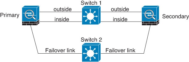
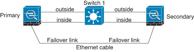
シナリオ 2:推奨
フェールオーバー リンクには、データ インターフェイスと同じスイッチを使用しないことを推奨します。代わりに、次の図に示すように、異なるスイッチを使用するか直接ケーブルを使用して、フェールオーバー リンクを接続します。
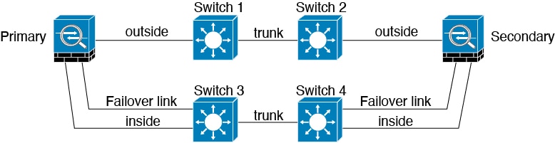
シナリオ 3:推奨
Firewall Threat Defense データ インターフェイスが複数セットのスイッチに接続されている場合、フェールオーバー リンクはいずれかのスイッチに接続できます。できれば、次の図に示すように、ネットワークのセキュアな側(内側)のスイッチに接続します。
MAC Addresses and IP Addresses in High availability
When you configure your interfaces, you can specify an active IP address and a standby IP address on the same network. Generally, when a failover occurs, the new active unit takes over the active IP addresses and MAC addresses. Because network devices see no change in the MAC to IP address pairing, no ARP entries change or time out anywhere on the network.
(注) |
Although recommended, the standby address is not required. Without a standby IP address, the active unit cannot perform network tests to check the standby interface health; it can only track the link state. You also cannot connect to the standby unit on that interface for management purposes. |
The IP address and MAC address for the state link do not change at failover.
Active/Standby IP Addresses and MAC Addresses
For Active/Standby High availability, see the following for IP address and MAC address usage during a failover event:
-
The active unit always uses the primary unit's IP addresses and MAC addresses.
-
When the active unit fails over, the standby unit assumes the IP addresses and MAC addresses of the failed unit and begins passing traffic.
-
When the failed unit comes back online, it is now in a standby state and takes over the standby IP addresses and MAC addresses.
However, if the secondary unit boots without detecting the primary unit, then the secondary unit becomes the active unit and uses its own MAC addresses, because it does not know the primary unit MAC addresses. When the primary unit becomes available, the secondary (active) unit changes the MAC addresses to those of the primary unit, which can cause an interruption in your network traffic. Similarly, if you swap out the primary unit with new hardware, a new MAC address is used.
If you disable high availability and set the failover configurations to a disabled state, you will need to manually resume high availability, or reboot the device. It is recommended to use the command configure high-availability resume and resume the high availability instead of rebooting the device. If you reload the standby unit with the failover configuration disabled, the standby unit boots up as the active unit and uses the primary unit's IP addresses and MAC addresses. This leads to duplicate IP addresses and causes network traffic disruptions. Use the command configure high-availability resume to enable failover and restore the traffic flow.
(注) |
If you enable failover on a standalone device, the data interfaces go down at negotiation state of failover, interrupting traffic. |
Virtual MAC addresses guard against this disruption, because the active MAC addresses are known to the secondary unit at startup, and remain the same in the case of new primary unit hardware. We recommend that you configure the virtual MAC address on both the primary and secondary units to ensure that the secondary unit uses the correct MAC addresses when it is the active unit, even if it comes online before the primary unit. If you do not configure virtual MAC addresses, you might need to clear the ARP tables on connected routers to restore traffic flow. The Firewall Threat Defense device does not send gratuitous ARPs for static NAT addresses when the MAC address changes, so connected routers do not learn of the MAC address change for these addresses.
Virtual MAC Addresses
The Firewall Threat Defense device has multiple methods to configure virtual MAC addresses. We recommend using only one method. If you set the MAC address using multiple methods, the MAC address used depends on many variables, and might not be predictable.
For multi-instance capability, the FXOS chassis autogenerates only primary MAC addresses for all interfaces. You can overwrite the generated MAC address with a virtual MAC address with both the primary and secondary MAC addresses, but predefining the secondary MAC address is not essential; setting the secondary MAC address does ensure that to-the-box management traffic is not interrupted in the case of new secondary unit hardware.
MAC Address Table Update in Failover
During failover, the device that is designated as the new active device generates multicast packets for each MAC address entry in the MAC table and sends them to all the bridge group interfaces. This action prompts the upstream switches in the bridge group to update their routing tables with the new active device's interface to ensure accurate traffic forwarding.
The time taken to generate multicast packets and update the routing tables of the upstream switches depends on the number of entries in the MAC address table and the number of bridge group interfaces. Use the show failover statistics state-switch-delay command to display statistics related to the delays encountered during failover events.
Stateful Failover
During Stateful Failover, the active unit continually passes per-connection state information to the standby unit. After a failover occurs, the same connection information is available at the new active unit. Supported end-user applications are not required to reconnect to keep the same communication session.
Supported Features
For Stateful Failover, the following state information is passed to the standby Firewall Threat Defense device:
-
NAT translation table.
-
TCP and UDP connections and states, including HTTP connection states. Other types of IP protocols, and ICMP, are not parsed by the active unit, because they get established on the new active unit when a new packet arrives.
-
Snort connection states, inspection results, and pin hole information, including strict TCP enforcement.
-
The ARP table
-
The Layer 2 bridge table (for bridge groups)
-
The ISAKMP and IPsec SA table
-
GTP PDP connection database
-
SIP signaling sessions and pin holes.
-
Static and dynamic routing tables—Stateful Failover participates in dynamic routing protocols, like OSPF and EIGRP, so routes that are learned through dynamic routing protocols on the active unit are maintained in a Routing Information Base (RIB) table on the standby unit. Upon a failover event, packets travel normally with minimal disruption to traffic because the active secondary unit initially has rules that mirror the primary unit. Immediately after failover, the re-convergence timer starts on the newly active unit. Then the epoch number for the RIB table increments. During re-convergence, OSPF and EIGRP routes become updated with a new epoch number. Once the timer is expired, stale route entries (determined by the epoch number) are removed from the table. The RIB then contains the newest routing protocol forwarding information on the newly active unit.
(注)
Routes are synchronized only for link-up or link-down events on an active unit. If the link goes up or down on the standby unit, dynamic routes sent from the active unit may be lost. This is normal, expected behavior.
-
DHCP Server—DHCP address leases are not replicated. However, a DHCP server configured on an interface will send a ping to make sure an address is not being used before granting the address to a DHCP client, so there is no impact to the service. State information is not relevant for DHCP relay or DDNS.
-
Access control policy decisions—Decisions related to traffic matching (including URL, URL category, geolocation, and so forth), intrusion detection, malware, and file type are preserved during failover. However, for connections being evaluated at the moment of failover, there are the following caveats:
-
AVC—App-ID verdicts are replicated, but not detection states. Proper synchronization occurs as long as the App-ID verdicts are complete and synchronized before failover occurs.
-
Intrusion detection state—Upon failover, once mid-flow pickup occurs, new inspections are completed, but old states are lost.
-
File malware blocking—The file disposition must become available before failover.
-
File type detection and blocking—The file type must be identified before failover. If failover occurs while the original active device is identifying the file, the file type is not synchronized. Even if your file policy blocks that file type, the new active device downloads the file.
-
-
User identity decisions from the identity policy, including the user-to-IP address mappings gathered passively through ISE Session Directory, and active authentication through captive portal. Users who are actively authenticating at the moment of failover might be prompted to authenticate again.
-
Network AMP—Cloud lookups are independent from each device, so failover does not affect this feature in general. Specifically:
-
Signature Lookup—If failover occurs in the middle of a file transmission, no file event is generated and no detection occurs.
-
File Storage—If failover occurs when the file is being stored, it is stored on the original active device. If the original active device went down while the file was being stored, the file does not get stored.
-
File Pre-classification (Local Analysis)—If failover occurs in the middle of pre-classification, detection fails.
-
File Dynamic Analysis (Connectivity to the cloud)—If failover occurs, the system might submit the file to the cloud.
-
Archive File Support—If failover occurs in the middle of an analysis, the system loses visibility into the file/archive.
-
Custom Blocking—If failover occurs, no events are generated.
-
-
Security Intelligence decisions. However, DNS-based decisions that are in process at the moment of failover are not completed.
-
RA VPN—Remote access VPN end users do not have to reauthenticate or reconnect the VPN session after a failover. However, applications operating over the VPN connection could lose packets during the failover process and not recover from the packet loss.
-
From all the connections, only established ones will be replicated on the Standby device.
Unsupported Features
For Stateful Failover, the following state information is not passed to the standby Firewall Threat Defense device:
-
Sessions in plaintext tunnels other than GREv0 and IPv4-in-IP. Sessions inside tunnels are not replicated and the new active node will not be able to reuse existing inspection verdicts to match the correct policy rules.
-
Decrypted TLS/SSL connections—The decryption states are not synchronized, and if the active unit fails, then decrypted connections will be reset. New connections will need to be established to the new active unit. Connections that are not decrypted (in other words, those that match a TLS/SSL Do Not Decrypt rule action) are not affected and are replicated correctly.
-
Multicast routing.
ハイ アベイラビリティのためのブリッジ グループの要件
ブリッジ グループを使用する場合は、ハイ アベイラビリティに関して特別な考慮事項があります。
アクティブ装置がスタンバイ装置にフェールオーバーするときに、スパニング ツリー プロトコル(STP)を実行しているスイッチ ポートは、トポロジ変更を検出すると 30 ~ 50 秒間ブロッキング状態に移行できます。ポートがブロッキング状態の間のブリッジ グループ メンバー インターフェイスでのトラフィックの損失を回避するために、次の回避策のいずれかを設定できます。
-
アクセス モードのスイッチ ポート:スイッチで STP PortFast 機能を有効にします。
interface interface_id
  spanning-tree portfast
PortFast 機能を設定すると、リンクアップと同時にポートが STP フォワーディング モードに遷移します。ポートは STP に参加し続けます。したがって、ポートがループの一部になる場合、最終的には STP ブロッキング モードに遷移します。
-
スイッチ ポートがトランク モードになっている場合、または STP PortFast を有効にできない場合は、フェールオーバー機能または STP の安定性に影響を与える、次のあまり望ましくない回避策のいずれかを使用できます。
-
ブリッジ グループおよびメンバー インターフェイスでインターフェイス モニタリングを無効にします。
-
フェールオーバー基準のインターフェイス保留時間を、ユニットがフェールオーバーする前に STP が収束できる大きな値に増やします。
-
スイッチの STP タイマーを短くして、STP がインターフェイス保留時間よりも早く収束できるようにします。
-
Failover Health Monitoring
The Firewall Threat Defense device monitors each unit for overall health and for interface health. This section includes information about how the Firewall Threat Defense device performs tests to determine the state of each unit.
Unit Health Monitoring
The Firewall Threat Defense device determines the health of the other unit by monitoring the failover link with hello messages. When a unit does not receive three consecutive hello messages on the failover link, the unit sends LANTEST messages on each data interface, including the failover link, to validate whether or not the peer is responsive. The action that the Firewall Threat Defense device takes depends on the response from the other unit. See the following possible actions:
-
If the Firewall Threat Defense device receives a response on the failover link, then it does not fail over.
-
If the Firewall Threat Defense device does not receive a response on the failover link, but it does receive a response on a data interface, then the unit does not failover. The failover link is marked as failed. You should restore the failover link as soon as possible because the unit cannot fail over to the standby while the failover link is down.
-
If the Firewall Threat Defense device does not receive a response on any interface, then the standby unit switches to active mode and classifies the other unit as failed.
(注) |
During a high-availability failover event, the Firewall Threat Defense device device may briefly appear as Offline in the device's health monitoring dashboard. This happens because health alerts are cleared during the process and are only updated after the process is complete. Wait for the failover operation to finish. |
Heartbeat Module Redundancy
Each unit in the HA periodically sends a broadcast keepalive heartbeat packet over the cluster control link. If the control plane is too busy handling traffic, sometimes the heartbeat packets do not reach the peers, or the peers do not process the heartbeat packets due to CPU overloading. When peers cannot communicate the keepalive status within the configurable timeout period, a false failover or split-brain scenario occurs.
The heartbeat module in the data plane helps to avoid the occurrence of false failover or split-brain due to traffic congestion in the control plane.
-
The additional heartbeat module works similarly to the control plane module but sends and receives heartbeat messages using the data plane transport infrastructure.
-
When the peer receives heartbeat packets in the data plane, a counter gets incremented.
-
If the heartbeat transfer in the control plane fails, the node checks the heartbeat counter in the data plane. If the counter is incrementing, then the peer is alive, and the cluster does not perform a failover in this situation.
(注) |
|
Interface Monitoring
When a unit does not receive hello messages on a monitored interface for 15 seconds, it runs interface tests. If one of the interface tests fails for an interface, but this same interface on the other unit continues to successfully pass traffic, then the interface is considered to be failed, and the device stops running tests.
If the threshold you define for the number of failed interfaces is met (see , and then ), and the active unit has more failed interfaces than the standby unit, then a failover occurs. If an interface fails on both units, then both interfaces go into the “Unknown” state and do not count towards the failover limit defined by failover interface policy.
An interface becomes operational again if it receives any traffic. A failed device returns to standby mode if the interface failure threshold is no longer met.
If an interface has IPv4 and IPv6 addresses configured on it, the device uses the IPv4 addresses to perform the health monitoring. If an interface has only IPv6 addresses configured on it, then the device uses IPv6 neighbor discovery instead of ARP to perform the health monitoring tests. For the broadcast ping test, the device uses the IPv6 all nodes address (FE02::1).
Interface Tests
The Firewall Threat Defense device uses the following interface tests. The duration of each test is approximately 1.5 seconds.
-
Link Up/Down test—A test of the interface status. If the Link Up/Down test indicates that the interface is down, then the device considers it failed, and testing stops. If the status is Up, then the device performs the Network Activity test.
-
Network Activity test—A received network activity test. At the start of the test, each unit clears its received packet count for its interfaces. As soon as a unit receives any eligible packets during the test, then the interface is considered operational. If both units receive traffic, then testing stops. If one unit receives traffic and the other unit does not, then the interface on the unit that does not receive traffic is considered failed, and testing stops. If neither unit receives traffic, then the device starts the ARP test.
-
ARP test—A test for successful ARP replies. Each unit sends a single ARP request for the IP address in the most recent entry in its ARP table. If the unit receives an ARP reply or other network traffic during the test, then the interface is considered operational. If the unit does not receive an ARP reply, then the device sends a single ARP request for the IP address in the next entry in the ARP table. If the unit receives an ARP reply or other network traffic during the test, then the interface is considered operational. If both units receive traffic, then testing stops. If one unit receives traffic, and the other unit does not, then the interface on the unit that does not receive traffic is considered failed, and testing stops. If neither unit receives traffic, then the device starts the Broadcast Ping test.
-
Broadcast Ping test—A test for successful ping replies. Each unit sends a broadcast ping, and then counts all received packets. If the unit receives any packets during the test, then the interface is considered operational. If both units receive traffic, then testing stops. If one unit receives traffic, and the other unit does not, then the interface on the unit that does not receive traffic is considered failed, and testing stops. If neither unit receives traffic, then testing starts over again with the ARP test. If both units continue to receive no traffic from the ARP and Broadcast Ping tests, then these tests will continue running in perpetuity.
Interface Status
Monitored interfaces can have the following status:
-
Unknown—Initial status. This status can also mean the status cannot be determined.
-
Normal—The interface is receiving traffic.
-
Normal (Waiting)—The interface is up, but has not yet received a hello packet from the corresponding interface on the peer unit.
-
Normal (Not-Monitored)—The interface is up, but is not monitored by the failover process.
-
Testing—Hello messages are not heard on the interface for five poll times.
-
Link Down—The interface or VLAN is administratively down.
-
Link Down (Waiting)—The interface or VLAN is administratively down and has not yet received a hello packet from the corresponding interface on the peer unit.
-
Link Down (Not-Monitored)—The interface or VLAN is administratively down, but is not monitored by the failover process.
-
No Link—The physical link for the interface is down.
-
No Link (Waiting)—The physical link for the interface is down and has not yet received a hello packet from the corresponding interface on the peer unit.
-
No Link (Not-Monitored)—The physical link for the interface is down, but is not monitored by the failover process.
-
Failed—No traffic is received on the interface, yet traffic is heard on the peer interface.
Failover Triggers and Detection Timing
The following events trigger failover in a Firepower high availability pair:
-
More than 50% of the Snort instances on the active unit are down.
-
Disk space on the active unit is more than 90% full.
-
The no failover active command is run on the active unit or the failover active command is run on the standby unit.
-
The active unit has more failed interfaces than the standby unit.
-
Interface failure on the active device exceeds the threshold configured.
By default, failure of a single interface causes failover. You can change the default value by configuring a threshold for the number of interfaces or a percentage of monitored interfaces that must fail for the failover to occur. If the threshold breaches on the active device, failover occurs. If the threshold breaches on the standby device, the unit moves to Fail state.
To change the default failover criteria, enter the following command in global configuration mode:
表 2. Command
Purpose
failover interface-policy num [%]
hostname (config)# failover interface-policy 20%Changes the default failover criteria.
When specifying a specific number of interfaces, the num argument can be from 1 to 250.
When specifying a percentage of interfaces, the num argument can be from 1 to 100.
The following table shows the failover triggering events and associated failure detection timing. If failover occurs, you can view the reason for the failover in the Message Center, along with various operations pertaining to the high availability pair. You can configure these thresholds to a value within the specified minimum-maximum range.
|
Failover Triggering Event |
Minimum |
Default |
Maximum |
|---|---|---|---|
|
Active unit loses power, hardware goes down, or the software reloads or crashes. When any of these occur, the monitored interfaces or failover link do not receives any hello message. |
800 milliseconds |
15 seconds |
45 seconds |
|
Active unit interface physical link down. |
500 milliseconds |
5 seconds |
15 seconds |
|
Active unit interface up, but connection problem causes interface testing. |
5 seconds |
25 seconds |
75 seconds |
About Active/Standby Failover
Active/Standby failover lets you use a standby Firewall Threat Defense device to take over the functionality of a failed unit. When the active unit fails, the standby unit becomes the active unit.
Primary/Secondary Roles and Active/Standby Status
When setting up Active/Standby failover, you configure one unit to be primary and the other to be secondary. During configuration, the primary unit's policies are synchronized to the secondary unit. At this point, the two units act as a single device for device and policy configuration. However, for events, dashboards, reports and health monitoring, they continue to display as separate devices.
The main differences between the two units in a failover pair are related to which unit is active and which unit is standby, namely which IP addresses to use and which unit actively passes traffic.
However, a few differences exist between the units based on which unit is primary (as specified in the configuration) and which unit is secondary:
-
The primary unit always becomes the active unit if both units start up at the same time (and are of equal operational health).
-
The primary unit MAC addresses are always coupled with the active IP addresses. The exception to this rule occurs when the secondary unit becomes active and cannot obtain the primary unit MAC addresses over the failover link. In this case, the secondary unit MAC addresses are used.
Active Unit Determination at Startup
The active unit is determined by the following:
-
If a unit boots and detects a peer already running as active, it becomes the standby unit.
-
If a unit boots and does not detect a peer, it becomes the active unit.
-
If both units boot simultaneously, then the primary unit becomes the active unit, and the secondary unit becomes the standby unit.
Failover Events
In Active/Standby failover, failover occurs on a unit basis.
The following table shows the failover action for each failure event. For each failure event, the table shows the failover policy (failover or no failover), the action taken by the active unit, the action taken by the standby unit, and any special notes about the failover condition and actions.
|
Failure Event |
Policy |
Active Unit Action |
Standby Unit Action |
Notes |
|---|---|---|---|---|
|
Active unit failed (power or hardware) |
Failover |
n/a |
Become active Mark active as failed |
No hello messages are received on any monitored interface or the failover link. |
|
Formerly active unit recovers |
No failover |
Become standby |
No action |
None. |
|
Standby unit failed (power or hardware) |
No failover |
Mark standby as failed |
n/a |
When the standby unit is marked as failed, then the active unit does not attempt to fail over, even if the interface failure threshold is surpassed. |
|
Failover link failed during operation |
No failover |
Mark failover link as failed |
Mark failover link as failed |
You should restore the failover link as soon as possible because the unit cannot fail over to the standby unit while the failover link is down. |
|
Failover link failed at startup |
No failover |
Become active Mark failover link as failed |
Become active Mark failover link as failed |
If the failover link is down at startup, both units become active. |
|
State link failed |
No failover |
No action |
No action |
State information becomes out of date, and sessions are terminated if a failover occurs. |
|
Interface failure on active unit above threshold |
Failover |
Mark active as failed |
Become active |
None. |
|
Interface failure on standby unit above threshold |
No failover |
No action |
Mark standby as failed |
When the standby unit is marked as failed, then the active unit does not attempt to fail over even if the interface failure threshold is surpassed. |


 フィードバック