- About this Guide
- ASR 5000 Hardware Platform Overview
- Installation Procedure Overview
- Chassis Installation
- Application Card Installation
- Line Card Installation
- Cabling the Switch Processor Input/Output Line Card
- Cabling the Fast Ethernet (10/100) Line Card
- Cabling the Gigabit Ethernet Line Cards
- Cabling the Optical (ATM) Line Cards
- Cabling the Channelized Line Cards
- Cabling the Power Filter Units
- Applying Power and Verifying the Installation
- System Monitoring
- Adding Application and Line Cards to an Existing Installation
- Removing and Installing SMC PC Cards
- Replacing the Chassis Air Filter
- Replacing a Power Filter Unit
- Replacing Upper or Lower Fan Tray
- Replacing Application Cards
- Replacing Line Cards
- Technical Specifications
- Safety, Electrical and EMC Certifications
- Environmental Specifications
- Hardware Product Support Matrix
- Preparing a Full-Height Line Card Slot
- RMA Shipping Procedures
- Spare Component Recommendations
Removing and Installing SMC PC Cards
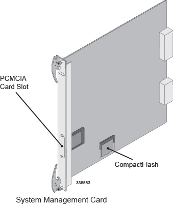
The ASR 5000 supports the use of PC Cards, also known as PCMCIA cards. These cards store software images, configuration files, and other data. Each SMC incorporates a single PCMCIA slot on its front panel.
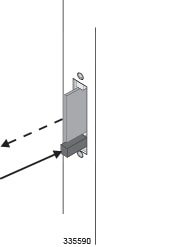
PC Cards are optional components. If your deployment requires the use of PC Cards, follow these instructions to safely install and remove the cards. The card slot accepts one ATA Type I or Type II PCMCIA card. Location of PCMCIA Slot
This chapter provides information and instructions for removing and installing the SMC's PCMCIA memory cards. It includes the following sections:
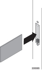
Installing PC Cards
This section provides instructions for installing a PC Card in the SMC.
If you are performing an initial installation of a PC Card, begin with step 1. If you are replacing a PC Card that you have removed according to the procedures in Removing PC Cards, begin with step 4.
 Caution | During installation, maintenance, and/or removal, wear a grounding wrist strap to avoid ESD damage to the components. Failure to do so could result in damage to sensitive electronic components and potentially void your warranty |
Removing PC Cards
Follow these instructions to remove a PC Card from the SMC.
Caution | During installation, maintenance, and/or removal, wear a grounding wrist strap to avoid ESD damage to the components. Failure to do so could result in damage to sensitive electronic components and potentially void your warranty. |
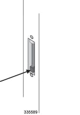
| Step 1 | Identify the slot from which the PC Card will be removed. |
| Step 2 | Use a Phillips
#1 screwdriver to remove the two screws securing the PC Card slot cover.
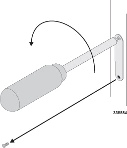
|
| Step 3 | Remove the PC
Card slot cover.
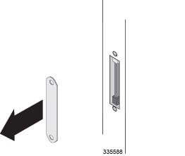
|
| Step 4 | Eject the PC Card from the slot. |
| Step 5 | Grasp the PC
Card and pull it out of the slot.
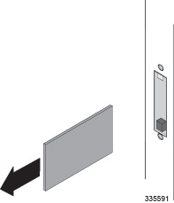
If you are installing a replacement PC Card, follow the instructions in Installing PC Cards. |
| Step 6 | Align the PC
Card slot cover over the open slot.
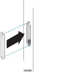
|
| Step 7 | Use the two
screws that you removed in step 2 of this procedure and a Phillips #1
screwdriver to fasten the PC Card slot cover.
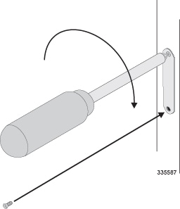
|
 Feedback