- About this Guide
- ASR 5000 Hardware Platform Overview
- Installation Procedure Overview
- Chassis Installation
- Application Card Installation
- Line Card Installation
- Cabling the Switch Processor Input/Output Line Card
- Cabling the Fast Ethernet (10/100) Line Card
- Cabling the Gigabit Ethernet Line Cards
- Cabling the Optical (ATM) Line Cards
- Cabling the Channelized Line Cards
- Cabling the Power Filter Units
- Applying Power and Verifying the Installation
- System Monitoring
- Adding Application and Line Cards to an Existing Installation
- Removing and Installing SMC PC Cards
- Replacing the Chassis Air Filter
- Replacing a Power Filter Unit
- Replacing Upper or Lower Fan Tray
- Replacing Application Cards
- Replacing Line Cards
- Technical Specifications
- Safety, Electrical and EMC Certifications
- Environmental Specifications
- Hardware Product Support Matrix
- Preparing a Full-Height Line Card Slot
- RMA Shipping Procedures
- Spare Component Recommendations
Installation Procedure Overview
This chapter briefly describes the steps and tools that are required for the physical installation of the chassis.
It includes the following sections:
- Chassis Components
- Installation at a Glance
- Required Tools and Equipment
- Site Prerequisites
- Protecting Against Electro-static Discharge
- Federal Communications Commission Warning
Chassis Components
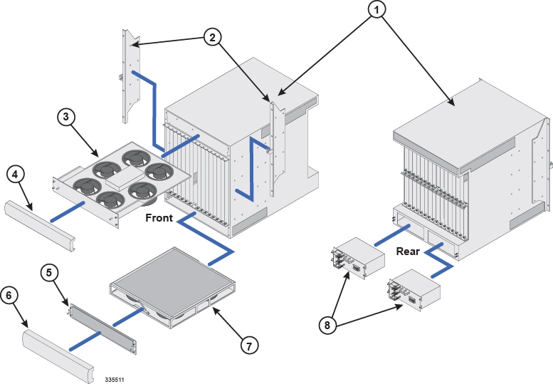
The following graphic and table illustrate the chassis and describe its subcomponents.
| Item | Description |
|---|---|
|
1 |
Chassis: Supports 16 front-loading slots for application cards and 32 rear-loading slots for line cards. The chassis ships with blanking panels over every slot except the following: 1, 8, 17, and 24. These are intentionally left uncovered for the initial installation of system components. |
|
2 |
Mounting brackets: Supports installation in a standard 19-inch rack or telecommunications cabinet. Standard and mid-mount options are supported. In addition, each bracket contains an electro-static discharge jack for use when handling equipment. |
|
3 |
Upper fan tray: Draws air up through the chassis for cooling and ventilation and exhausts the air through the vents at the upper-rear of the chassis. |
|
4 |
Upper bezel: Covers the upper fan tray bay. |
|
5 |
Lower fan tray cover/EMI shield: Secures the lower fan tray assembly in place and serves as an EMI shield. The cover also provides an air baffle allowing air to enter into the chassis. |
|
6 |
Lower bezel: Covers the lower fan tray bay. |
|
7 |
Lower fan tray assembly: Draws air into the chassis through the chassis' front and sides for cooling and ventilation. It is equipped with a particulate air filter to prevent dust and debris from entering the system. |
|
8 |
Power Filter Units (PFUs): Each of the system's two 165 amp PFUs provides -48 VDC power to the chassis and its associated cards. Each load-sharing PFU operates independently from the other to ensure maximum power feed redundancy. |
Installation at a Glance
The list below summarizes the installation process for the chassis.
 Note | Unpacking instructions are not provided in this document. Please refer to the Unpacking the ASR 5000 Chassis document shipped with the system, for information and instructions on this topic. The chassis and cards are shipped separately. |
-
Unpack the chassis and cards
-
Determine which chassis mounting option to use: standard or mid-mount.
-
Install the chassis into a standard 19-inch equipment rack or telecommunications cabinet.
- Connect the chassis to earth ground.
-
Install application cards into the front of the chassis.
-
Install line cards into the rear of the chassis.
-
Connect data cables to the line cards.
-
Connect power cables to the chassis.
-
Apply power to the chassis.
-
Verify that the installation was successful.
Once the installation has been validated, you will be directed to the System Administration Guide for instructions on how to configure the system for operation.
Required Tools and Equipment
This section lists the tools and equipment needed for installation.
Hand Tools
The following hand tools are required for installation of the chassis, application and line cards, fan tray assemblies, and power filter units:
Phillips #1 and #2 hand screwdrivers. Used to tighten thumb-screws on cards, fan tray assemblies, PFUs, and mounting brackets.

CautionThe inappropriate use of electric or pneumatic torque drivers, or power drill/impact drivers to loosen or tighten fasteners may result in damage to system components.
9/16-inch nut driver or ratchet and socket set. Used to connect power and return cables.
3/8-inch nut driver or ratchet and socket set. Used to connect grounding cables.
Torque wrench (rated 50 in-lb [5.65 N-m]) with 9/16-inch socket for tightening lugs to power terminals.
Grounding wrist and/or heel straps. Used to prevent Electro-Static Discharge (ESD) as discussed in the Protecting Against Electro-static Discharge section that follows.
Caution | During installation, maintenance, and/or removal, wear grounding wrist and/or heel straps to avoid ESD damage to the components. Failure to do so could result in damage to sensitive electronic components and potentially void your warranty. |
Equipment
The following equipment is necessary to install the chassis and verify that it is ready for configuration:
Standard 19-inch (48.26 cm) equipment rack or telecommunications cabinet with mounting hardware. Additional hardware, such as extension brackets (not supplied), may be used to install the chassis in a standard 23-inch (58.42 cm) cabinet or rack.
Voltmeter to measure input voltages at the PFU terminals.
Heat gun for installing shrink wrap tubing over power cable lugs.
Console cable supplied with the Switch Processor I/O (SPIO) line card.
A computer or terminal server with a 9-pin RS-232C serial port, or 25-to-9-pin male RS-232C adapter. It will be connected to the SPIO's Console port for accessing the command line interface (CLI) for initial system configuration.
Pallet jack and/or chassis lift to move and position the ASR 5000 chassis. Without such mechanical assistance, moving and positioning the chassis will require multiple craftpersons trained to safely handle heavy rack-mounted units.
Site Prerequisites
This section summarizes power, grounding, environment, and clearance requirements that must be met prior to installing and operating the ASR 5000. For detailed information, refer to the Technical Specifications chapter.
Power and Grounding
Each PFU requires a power feed of 160A @ -48VDC (nominal). The feeds should be routed to the installation rack from the site power supply using adequately sized conductors and circuit breakers in accordance with local electrical codes.
The chassis must be grounded to a site ground point using the recommended conductors and lugs. The ground point should be in close proximity to the ASR 5000 chassis to assure adequate conductivity.
Environment
The site's heating ventilation and air conditioning (HVAC) systems must be sized to maintain the operating temperatures and relative humidity specified in the Technical Specifications chapter. HVAC capacity requirements will vary based on the system configuration and associated power draw, as well as the operational characteristics of other equipment installed at the site.
Clearance
Adequate clearance must be maintained at the front and rear of the ASR 5000 chassis to assure proper air flow and allow maintenance access for the installation, removal and replacement of components. The recommended clearance is 30 to 36 inches (76 to 92 centimeters) at the front and rear of the chassis.
Protecting Against Electro-static Discharge
Electro-Static Discharge (ESD) can cause serious damage to sensitive components on the chassis, its sub-components, and/or the cards installed in the chassis. To prevent damage from ESD, you must take proper grounding precautions before handling the chassis or any of its components.
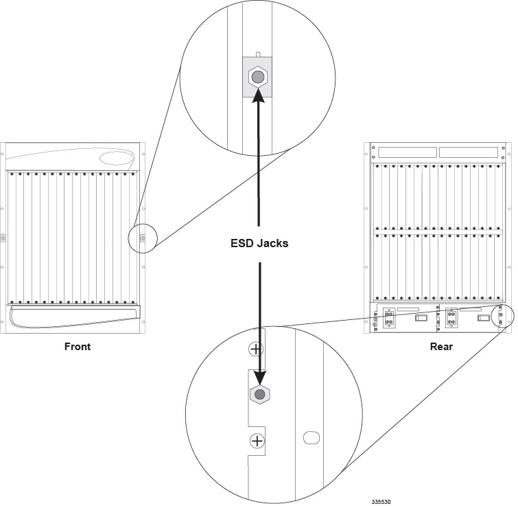
To aid in the prevention of ESD damage, the chassis and its mounting brackets are equipped with ESD jacks. Use the jacks in conjunction with grounding wrist straps when handling the chassis and/or its components. The following figure shows the location of the jacks.
Before using the ESD jacks on the chassis and its mounting brackets to provide protection, you must first connect the chassis to earth ground as described in the Chassis Installation chapter of this document.
Federal Communications Commission Warning
This device complies with the limits for a Class A digital device, pursuant to Part 15 of the FCC Rules and Regulations. Operation is subject to the following two conditions:
This device may not cause harmful interference.
This device must withstand any interference received, including interference that may cause undesired operation.
The system platform has been tested and found to comply with the limits for a Class A digital device pursuant to Part 15 of the FCC Rules and Regulations. These limits are designed to provide reasonable protection against harmful interference when this equipment is operated in a commercial environment. This equipment generates, uses, and can radiate radio-frequency energy and, if not installed and used in accordance with the instruction manual, may cause harmful interference to radio and television communications. Operation of this equipment in a residential area is likely to cause interference in which case the user will be required to correct the interference at his or her own expense.
Modifications to this product not authorized by Cisco could void the FCC approval and negate your authority to operate the product.
Shielded cables must be used with this unit to ensure compliance with the FCC Class A limits.
ICS Notice
This Class A digital apparatus complies with Canadian ICES-003.
Cet appareil numérique de la classe A est conforme à la norme NMB-003 du Canada.
Laser Notice
The lasers in this equipment are Class 1 devices. Class 1 laser devices are not considered to be hazardous.
 Feedback