- About this Guide
- ASR 5000 Hardware Platform Overview
- Installation Procedure Overview
- Chassis Installation
- Application Card Installation
- Line Card Installation
- Cabling the Switch Processor Input/Output Line Card
- Cabling the Fast Ethernet (10/100) Line Card
- Cabling the Gigabit Ethernet Line Cards
- Cabling the Optical (ATM) Line Cards
- Cabling the Channelized Line Cards
- Cabling the Power Filter Units
- Applying Power and Verifying the Installation
- System Monitoring
- Adding Application and Line Cards to an Existing Installation
- Removing and Installing SMC PC Cards
- Replacing the Chassis Air Filter
- Replacing a Power Filter Unit
- Replacing Upper or Lower Fan Tray
- Replacing Application Cards
- Replacing Line Cards
- Technical Specifications
- Safety, Electrical and EMC Certifications
- Environmental Specifications
- Hardware Product Support Matrix
- Preparing a Full-Height Line Card Slot
- RMA Shipping Procedures
- Spare Component Recommendations
Replacing Line Cards
This chapter provides information on replacing a failed line card.
 Caution | During installation, maintenance, and/or removal, wear a grounding wrist strap to avoid ESD damage to the components. Failure to do so could result in damage to sensitive electronic components and potentially void your warranty. |
This chapter includes the following sections:
- Determining Whether a Line Card has Failed
- Removing the Line Card
- Installing the Line Card
- What to do with the Failed Line Card
Determining Whether a Line Card has Failed
There are several ways the chassis indicates a line card failure. The first indicator is that the Status LED on the System Management Card (SMC) turns red to indicate the failure of a chassis component. Another is that the Run/Fail LED turns red or turns off on a line card that has a problem.
If you see either of these indicators, use the CLI or check the Simple Network Management Protocol (SNMP) traps to determine the nature of the problem.
Using the CLI
Enter the following CLI commands in Exec mode to monitor line cards:
show card diag slot_#
slot_# is the chassis slot number in which a particular card that you wish to monitor is installed. For line cards, slot_# would is an integer between 17 and 48. The following is a sample output for this command issued to monitor the card in chassis slot 24:
Card 24:
    Card Usable                       : Yes
    Card Tests                        : Pass
show card info slot_#
Use the upper slot number to specify the location of an XGLC. Slot numbering for other installed half-height cards is maintained: 17 to 32 and 33 to 48, regardless of the number of installed XGLCs.
Card 24:
    Slot Type                : SPIO
    Card Type                : Switch Processing I/O Card
    Operational State        : Active
    Redundancy Mode          : Port Mode
    Last State Change        : Thursday January 27 16:28:49 EST 2011
    Administrative State     : Enabled
    Card Lock                : Locked
    Halt Issued              : No
    Reboot Pending           : No
    Upgrade In Progress      : No
    Card Usable              : Yes
    Single Point of Failure  : No
    Attachment               : 8 (Switch Management Card)
    Temperature              : 32 C (limit 85 C)
    Voltage:                 : Good
    Card LEDs                : Run/Fail: Green | Active: Green | Standby: Off
If any of the above information appears to be erroneous such as the operational state or an LED state, check for any of the SNMP alarms listed in Using SNMP Traps.
Using SNMP Traps
The system supports SNMP traps that are triggered for conditions that may indicate the need to replace a line card. The system provides the traps listed in the table below.
| SNMP Trap | Description |
|---|---|
starCardVoltageFailure |
A voltage regulation failure has been detected in a card. |
starCardBootFailed |
A card has failed to start up properly. The card is not operational. |
starCardFailed |
The card has failed and is no longer operational. |
starCardSWFailed |
An unrecoverable software error has occurred on the card. |
starCardRCCFailed |
The RCC has failed. |
Removing the Line Card
This section describes how to remove a line card.
Before removing and replacing a line card on an active system, refer to the System Administration Guide for instructions on how to switch services to a redundant (standby) card.
Installing the Line Card
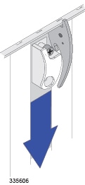
| Step 1 | Slide the interlock switch on the card fully downward. Flip the ejector levers outward and away from the card's faceplate. | ||||||||||||||
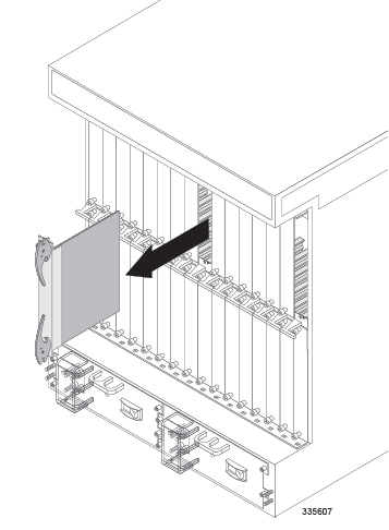
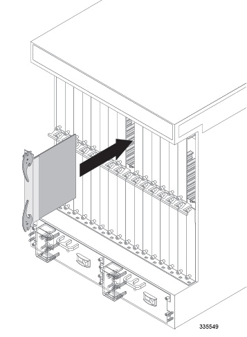
| Step 2 | Hold the card by
its ejector levers and align it with the upper and lower card guides of the
chassis slot. Gently slide the card into the slot until the levers touch the
chassis frame.
| ||||||||||||||
| Step 3 | Push the ejector levers inward firmly and straight until the card is firmly seated in the chassis midplane and the ejector levers can be pushed in no further. Press firmly on the card's faceplate to ensure that it is fully seated. The card's front panel should be flush against the chassis' upper and lower card mounts for the slot. | ||||||||||||||
| Step 4 | Slide the
interlock switch on the front panel of the line card upward to lock the ejector
tab in place. The flange on the left-side of the interlock switch prevents
movement of the ejector tab when raised completely.
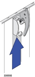
You must slide the interlock switch upward before securing the card's top screw to the mounting rail. | ||||||||||||||
| Step 5 | Use a Phillips #2 screwdriver to tighten the screws at the top and bottom of the line card's front panel to secure the card to the chassis. | ||||||||||||||
| Step 6 | Refer to the
destination label on each cable and re-attach the cables to the line card.
Refer to the following table to locate the chapter of this guide that provides
information and instructions on cabling the line card.
|
What to do with the Failed Line Card
If the failed line card is still under warranty, return it to the vendor for repair.
If the failed line card is out of warranty, contact Cisco to determine if you can send it in for repair at an additional cost.
Disposal of this product should be performed in accordance with all national laws and regulations
Refer to the support area of http://www.cisco.com for up-to-date product documentation pertaining to installation, configuration, and maintenance. A valid username and password are required to use this site. Please contact your local sales or service representative for additional information.
For additional information on the RMA process, see the RMA Shipping Procedures appendix.
 Feedback