- About this Guide
- ASR 5000 Hardware Platform Overview
- Installation Procedure Overview
- Chassis Installation
- Application Card Installation
- Line Card Installation
- Cabling the Switch Processor Input/Output Line Card
- Cabling the Fast Ethernet (10/100) Line Card
- Cabling the Gigabit Ethernet Line Cards
- Cabling the Optical (ATM) Line Cards
- Cabling the Channelized Line Cards
- Cabling the Power Filter Units
- Applying Power and Verifying the Installation
- System Monitoring
- Adding Application and Line Cards to an Existing Installation
- Removing and Installing SMC PC Cards
- Replacing the Chassis Air Filter
- Replacing a Power Filter Unit
- Replacing Upper or Lower Fan Tray
- Replacing Application Cards
- Replacing Line Cards
- Technical Specifications
- Safety, Electrical and EMC Certifications
- Environmental Specifications
- Hardware Product Support Matrix
- Preparing a Full-Height Line Card Slot
- RMA Shipping Procedures
- Spare Component Recommendations
Replacing a Power Filter Unit
Up to two -48 VDC Power Filter Unit (PFU) assemblies can be installed in the ASR 5000 chassis. Two PFUs provide load-balancing and redundancy. The PFUs are located in the lower-rear of the chassis.
 Caution | Although a single PFU can provide power for a fully loaded chassis, it is strongly recommended that two PFUs always remain installed for load-balancing and redundancy. |
Caution | During installation, maintenance, and/or removal, wear a grounding wrist strap to avoid ESD damage to the components. Failure to do so could result in damage to sensitive electronic components and potentially void your warranty. |
This chapter provides instructions for replacing a PFU in the event of failure. It includes the following sections:
- Determining that a PFU has Failed
- Removing the Failed PFU
- Installing the Replacement PFU
- What to do with the Failed PFU
Determining that a PFU has Failed
The chassis can use one of several mechanisms to indicate a PFU failure. The first indicator is when the POWER LED on the PFU is off. If the LED is off and a starPowerState SNMP trap is generated with a value of Failed (2), the PFU must be replaced.
Verify that the power switch is in the ON position.
Verify that the RTN and -VDC lugs are attached according to the instructions provided in this document.
Verify that the ground lug is attached according to the instructions provided in this document.
Verify that the power source is on and is supplying the correct voltage and sufficient current.
Check the cables from the power source to the rack for continuity.
If a fuse panel is installed between the Power Distribution Frame (PDF) and the chassis, verify that the fuses are intact.
If a fuse panel is installed between the PDF and the chassis, check the cables from the fuse panel to the chassis for continuity.
Removing the Failed PFU
In the event of a PFU failure, follow these instructions to safely remove the PFU from the chassis.
| Step 1 | Power down the
PFU by flipping the circuit breaker on the PFU to the OFF position. If the
circuit breaker on your PFU is equipped with a locking clip, move the clip to
the right to unlock the circuit breaker's actuator.
| ||
| Step 2 | Shut down the
power source to the failed PFU.
| ||
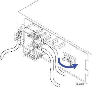
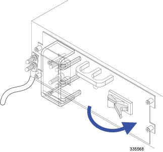
| Step 3 | Use a Phillips #2 screwdriver to remove the plastic cover from the power terminals. | ||
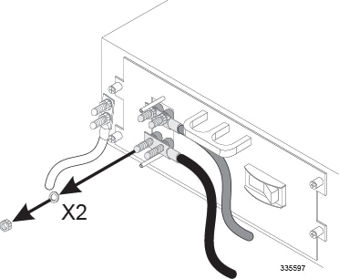
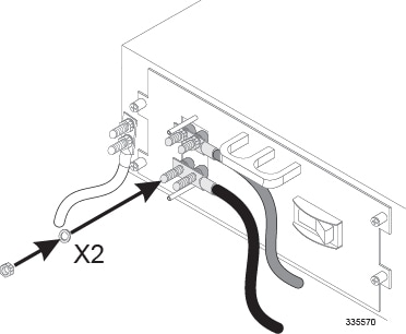
| Step 4 | Remove the cable from the -VDC terminals as described below. The -VDC terminals are the two terminals located at the bottom of the PFU. | ||
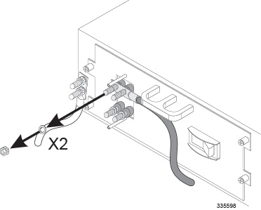
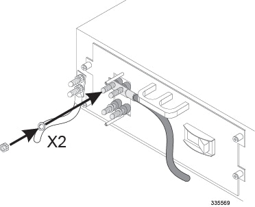
| Step 5 | Remove the cables from both RTN terminals as described below. The RTN terminals are the two terminals located directly above the -VDC terminals. | ||
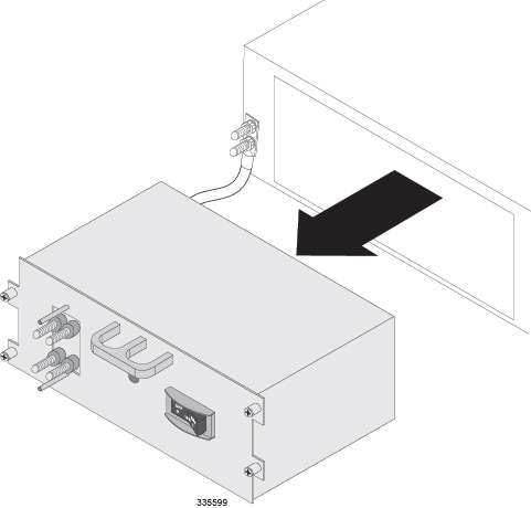
| Step 6 | Use a Phillips #2 screwdriver to loosen the four screws that secure the PFU to the chassis. | ||
| Step 7 | Grasp the handle
on the PFU and gently pull it toward you. The PFU should easily slide out of
the chassis.
| ||
| Step 8 | Proceed to Installing the Replacement PFU. |
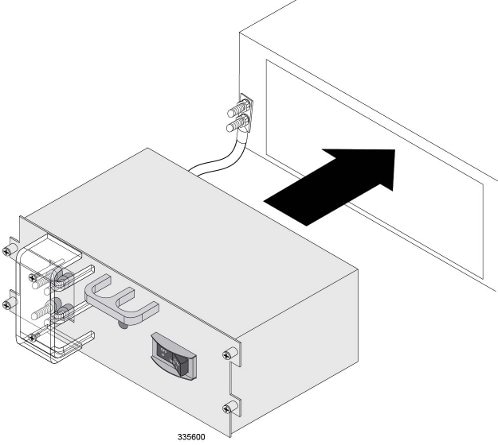
Installing the Replacement PFU
Follow the instructions below to install the replacement PFU in the chassis.
What to do with the Failed PFU
If the failed PFU is still under warranty, return it to the vendor for repair.
If the failed PFU is out of warranty, contact Cisco to determine if it can be sent in for repair at an additional cost.
Disposal of this product should be performed in accordance with all national laws and regulations.
Refer to the support area of http://www.cisco.com for up-to-date product documentation pertaining to installation, configuration, and maintenance. A valid username and password is required to use this site. Please contact your local sales or service representative for additional information.
For additional information on the RMA process, see the RMA Shipping Procedures appendix.
 Feedback