- About this Guide
- ASR 5000 Hardware Platform Overview
- Installation Procedure Overview
- Chassis Installation
- Application Card Installation
- Line Card Installation
- Cabling the Switch Processor Input/Output Line Card
- Cabling the Fast Ethernet (10/100) Line Card
- Cabling the Gigabit Ethernet Line Cards
- Cabling the Optical (ATM) Line Cards
- Cabling the Channelized Line Cards
- Cabling the Power Filter Units
- Applying Power and Verifying the Installation
- System Monitoring
- Adding Application and Line Cards to an Existing Installation
- Removing and Installing SMC PC Cards
- Replacing the Chassis Air Filter
- Replacing a Power Filter Unit
- Replacing Upper or Lower Fan Tray
- Replacing Application Cards
- Replacing Line Cards
- Technical Specifications
- Safety, Electrical and EMC Certifications
- Environmental Specifications
- Hardware Product Support Matrix
- Preparing a Full-Height Line Card Slot
- RMA Shipping Procedures
- Spare Component Recommendations
- Understanding the System Boot Process
- Applying Power to the Chassis
- Verifying the Installation
- Checking the LED on the PFU
- Checking the LEDs on the SMC(s)
- Checking the LEDs on Packet Processing Cards
- Checking the LEDs on the SPIO(s)
- Checking the LEDson the Ethernet Line Cards
- Checking the Card-Level LEDs on the Optical (ATM) Line Card
- Checking the Alarm and Link LEDs on the Optical (ATM/POS OC-3) Line Card
- Card-Level LEDs on the Channelized (STM-1/OC-3) Line Card
- Checking the Alarm and Link LEDs on the Channelized Line Card 2
- Checking the LEDs on the RCC(s)
Applying Power and Verifying the Installation
This chapter provides information and instructions for understanding the boot process, applying power to the chassis, and verifying that the installation was successful.
This chapter assumes that the ASR 5000 chassis, its sub-components, as well as application and line cards have been physically installed. The system has also been cabled to interoperate with management and traffic networks.
This chapter includes the following sections:
- Understanding the System Boot Process
- Applying Power to the Chassis
- Verifying the Installation
- Completing Initial System Configuration
Understanding the System Boot Process
Before you apply power to the system, it is important that you understand the boot process and how the hardware components are brought on line.
The following figure provides a flowchart that explains each step in the startup process.
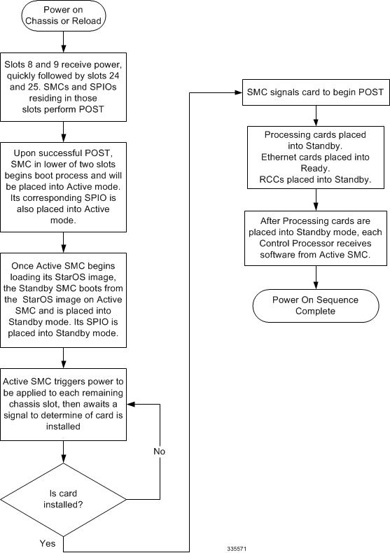
 Caution | Never operate the chassis if any slots are uncovered. This reduces airflow through the chassis and could cause it to overheat. Make sure a card or blanking panel is installed in every chassis slot at all times. |
Applying Power to the Chassis
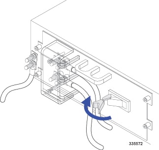
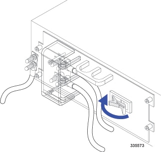
Once you have properly connected all power and ground cables to the chassis according to the instructions in "Cabling the Power Filter Units", follow the instructions below to apply power to the system.
Verifying the Installation
When power is applied to the chassis, power is provided to the upper and lower fan trays, and every installed application and line card.
Each PFU, application card, and line card installed in the chassis has light emitting diodes (LEDs) that indicate its status. This section describes how to interpret the LEDs to verify that all of the installed components are functioning properly.
As the system progresses through its boot process, some cards may have no immediate LED activity. Line cards have sporadic Link and Activity LED activity. It is recommended that you allow several minutes to elapse prior to checking the LEDs on the various cards to verify the installation.
- Checking the LED on the PFU
- Checking the LEDs on the SMC(s)
- Checking the LEDs on Packet Processing Cards
- Checking the LEDs on the SPIO(s)
- Checking the LEDs on the Ethernet Line Cards
- Checking the Card-Level LEDs on the Optical (ATM) Line Card
- Checking the Alarm and Link LEDs on the Optical (ATM/POS OC-3) Line Card
- Card-Level LEDs on the Channelized (STM-1/OC-3) Line Card
- Checking the Alarm and Link LEDs on the Channelized Line Card 2
- Checking the LEDs on the RCC(s)
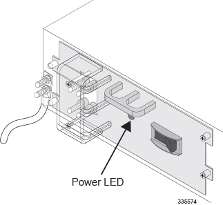
Checking the LED on the PFU
Each PFU has a single status LED labeled POWER. This LED is green during normal operating conditions.
| Color | Description | Troubleshooting |
|---|---|---|
|
Green |
PFU powered with no errors detected |
None needed. |
|
None |
PFU is not receiving power |
Verify that the power switch is in the ON position. |
|
Verify that the RTN and -VDC lugs are attached properly according to the instructions provided in this document. |
||
|
Verify that the ground lug is attached properly. |
||
|
Verify that the power source is on and is supplying the correct voltage and sufficient current. |
||
|
Check the cables from the power source to the rack for continuity. |
||
|
If a fuse panel is installed between the Power Distribution Frame (PDF) and the chassis, verify that the fuses are intact. |
||
|
If a fuse panel is installed between the PDF and the chassis, check the cables from the fuse panel to the chassis for continuity. |
||
|
If all of the above suggestions have been verified, then it is likely that the PFU is not functional. Please contact your service representative. |
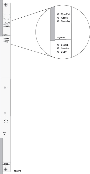
Checking the LEDs on the SMC(s)
Each SMC is equipped with the following LEDs as shown in the following figure:
The possible states for all SMC LEDs are described in the sections that follow.
- SMC Run/Fail LED States
- SMC Active LED States
- SMC Standby LED States
- SMC Status LED States
- SMC Service LED States
- SMC Busy LED States
SMC Run/Fail LED States
The SMC's Run/Fail LED indicates the overall status of the card. This LED is illuminated steady green for normal operation.
| Color | Description | Troubleshooting |
|---|---|---|
|
Green |
Card powered with no errors detected |
None needed. |
|
Blinking Green |
Card is initializing and/or loading software |
This is normal operation during boot-up. |
|
Red |
Card powered with error(s) detected |
Errors were detected during the POSTs. It is likely that the errors were logged to the system's command line interface during boot. Refer to the System Administration Guide for troubleshooting information. |
|
None |
Card is not receiving power |
Verify that the POWER LEDs on the PFUs are green. If they are not, refer to Checking the LED on the PFU for troubleshooting information. |
|
Verify that the power source is supplying ample voltage and current to the chassis. |
||
|
Verify that the card is properly installed per the instructions in this document. |
||
|
If all of the above suggestions have been verified, it is possible that the SMC is not functional. Please contact your service representative. |
SMC Active LED States
The Active LED on the SMC indicates that the software is loaded on the card and it is ready for operation. For the SMC installed in slot 8, this LED is illuminated green during normal operation. For the SMC installed in slot 9, this LED is off during normal operation.
| Color | Description | Troubleshooting |
|---|---|---|
|
Green |
Card is active |
None needed for the SMC in slot 8. If green for the SMC in slot 9, verify that the SMC in slot 8 is installed properly according to the instructions in this document. |
|
Blinking Green |
Tasks or processes being migrated from the active SMC to the redundant/secondary SMC |
Verify that the Standby LED on the redundant SMC is also blinking green. If so, there is an issue with the active SMC. |
|
None |
Card is not receiving power OR Card in Standby Mode |
Verify that the Run/Fail LED is green. If so, the card is receiving power and POST test results are positive. If it is off, refer to SMC Run/Fail LED States for troubleshooting information. |
|
Check the state of the Standby LED. If it is green, the card is in standby mode. |
SMC Standby LED States
The Standby LED on the SMC indicates that software is loaded on the card and it is serving as a redundant component. For the SMC installed in slot 9, this LED is illuminated steady green during normal operation. For the SMC installed in slot 8, this LED is off during normal operation.
| Color | Description | Troubleshooting |
|---|---|---|
|
Green |
Card is in redundant mode |
None needed for the SMC in slot 9. If green for the SMC in slot 8, then verify it is installed properly according to the instructions in this document. |
|
Blinking Green |
Tasks or processes are being migrated from the active SMC to the redundant/secondary SMC |
Verify that the Active LED on the redundant SMC is also blinking green. If so, there is an issue with the active SMC. |
|
None |
Card is not receiving power OR Card in Active Mode |
Verify that the Run/Fail LED is green. If so, the card is receiving power and POST test results are positive. If it is off, refer to SMC Run/Fail LED States for troubleshooting information. |
|
Check the state of the Active LED. If it is green, the card is in active mode. |
SMC Status LED States
The Status LEDs on the SMC indicate the status of system level hardware, such as installed cards, fans, and PFUs. This LED is illuminated steady green during normal operation.
| Color | Description | Troubleshooting |
|---|---|---|
|
Green |
No system errors detected |
None needed. |
|
Red |
Failures Detected |
Check the Run/Fail LEDs for all installed application cards, and line cards. If any are red or off, refer to the troubleshooting information in this chapter pertaining to that device. |
|
None |
Card is not receiving power |
Verify that the Run/Fail LED is green. If so, the card is receiving power and POST test results are positive. If it is off, refer to SMC Run/Fail LED States for troubleshooting information. |
SMC Service LED States
The Service LEDs on the SMCs indicate that the system requires maintenance or service. Examples are that the system could not locate a a valid software image at boot-up, or that a high temperature condition exists.
This LED is off during normal operation.
The possible states for this LED are described in the following table. Use the troubleshooting information in the table to diagnose the problem.
| Color | Description | Troubleshooting |
|---|---|---|
Yellow |
System requires maintenance (fan filter, temperature warning, PFU outage etc.) |
Refer to the appropriate section of this guide for troubleshooting information. |
None |
Card is not receiving power |
No maintenance needed. |
SMC Busy LED States
The Busy LEDs on the SMCs indicate that there is activity on one of their memory devices:
-
CompactFlash module
-
PCMCIA device
-
Nand Flash (used to store SMC firmware)
-
Hard drive
The possible states for this LED are described in the following table. If the LED is not green, use the troubleshooting information in the table to diagnose the problem.
| Color | Description | Troubleshooting |
|---|---|---|
|
Green/ Blinking Green |
Data is being read from or written to one of the memory devices. |
No maintenance needed. |
|
NOTE: If you are removing an SMC from the chassis, it is recommended that you wait until this LED is off to ensure the integrity of all data being transferred to or from the memory device. |
||
|
None |
The memory devices are not in use. |
No maintenance needed. |
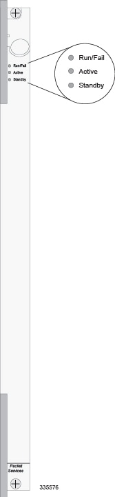
Checking the LEDs on Packet Processing Cards
Each packet processing card is equipped with status LEDs as shown in the following figure:
The possible states for all of the packet processing card's LEDs are described in the sections that follow.
- PSCA, PSC2, PSC3 and PPC Run/Fail LED States
- PSCA, PSC2, PSC3 and PPC Active LED States
- PSCA, PSC2, PSC3 and PPC Card Standby LED States
PSCA, PSC2, PSC3 and PPC Run/Fail LED States
The packet processing card's Run/Fail LED indicates the overall status of the card. This LED is illuminated steady green during normal operation.
| Color | Description | Troubleshooting |
|---|---|---|
|
Green |
Card powered with no errors detected |
None needed. |
|
Blinking Green |
Card is initializing and/or loading software |
None needed. |
|
Red |
Card powered with error(s) detected |
Errors were detected during the POSTs. It is likely that the errors were logged to the system's command line interface during the boot process. |
|
None |
Card is not receiving power |
Verify that the POWER LEDs on the PFUs are green. If they are not, refer to Checking the LED on the PFU for troubleshooting information. |
|
Verify that the power source is supplying ample voltage and current to the chassis. |
||
|
Verify that the card is properly installed per the instructions in this document. |
||
|
If all of the above suggestions have been verified, it is possible that the packet processing card is not functional. Please contact your service representative. |
PSCA, PSC2, PSC3 and PPC Active LED States
The Active LED on the packet processing card indicates that the software is loaded on the card and that the card is ready for operation. When the system first boots up, all installed packet processing cards are booted into standby mode. You must then configure the system to designate which packet processing cards are to serve as redundant components (in standby mode) and which are to function as active components.
| Color | Description | Troubleshooting |
|---|---|---|
|
Green |
Card is active |
The first time power is applied to the system, all of the packet processing cards should be booted into the standby mode. Therefore, this LED should be off. |
|
Blinking Green |
Tasks or processes are being migrated from an active packet processing card to a redundant/secondary packet processing card |
Verify that the Standby LED on a redundant packet processing card is also blinking green. If so, there is an issue with the packet processing card that was active and is transferring its processes. |
|
None |
Card is not receiving power OR Card in Standby Mode |
Verify that the Run/Fail LED is green. If so, the card is receiving power and POST test results are positive. If it is off, refer to the PSCA, PSC2, PSC3 and PPC Run/Fail LED States for troubleshooting information. |
|
Check the state of the Standby LED. If it is green, the card is in standby mode. This is normal operation for the initial power-up. |
PSCA, PSC2, PSC3 and PPC Card Standby LED States
The Standby LED on the packet processing card indicates that software is loaded on the card and the card is serving as a redundant component. When the system first boots up, all installed packet processing cards are booted into standby mode. You must then configure the system to designate which packet processing cards are to serve as redundant components (in standby mode) and which are to function as active components.
| Color | Description | Troubleshooting |
|---|---|---|
|
Green |
Card is in redundant mode |
The first time power is applied to the system, all of the packet processing cards should be booted into the standby mode. This is normal operation. |
|
Blinking Green |
Tasks or processes being migrated from the active SMC to the redundant/secondary SMC |
Verify that the Active LED on the redundant packet processing card is also blinking green. If so, there is an issue with the active packet processing card and the system is transferring its processes. |
|
None |
Card is not receiving power OR Card is in Active Mode |
Verify that the Run/Fail LED is green. If so, the card is receiving power and POST test results are positive. If it is off, refer to PSCA, PSC2, PSC3 and PPC Run/Fail LED States for troubleshooting information. |
|
Check the state of the Active LED. If it is green, the card is in active mode. |
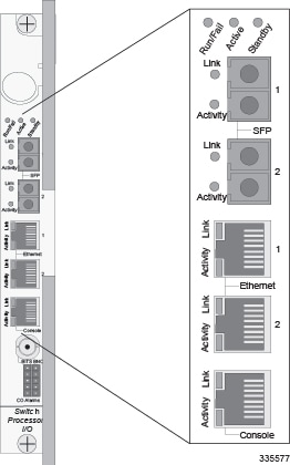
Checking the LEDs on the SPIO(s)
Each SPIO is equipped with status LEDs:
-
Link
-
Activity
The following figure shows the LEDs on the SPIO.
The possible states for all of the SPIO's LEDs are described in the sections that follow.
- SPIO Run/Fail LED States
- SPIO Active LED States
- SPIO Standby LED States
- SPIO Interface Link LED States
- SPIO Interface Activity LED States
SPIO Run/Fail LED States
The SPIO's Run/ Fail LED indicates the overall status of the card. This LED is illuminated steady green for normal operation.
| Color | Description | Troubleshooting |
|---|---|---|
|
Green |
Card powered with no errors detected |
None needed. |
|
Red |
Card powered with error(s) detected |
Errors were detected during the POSTs. It is likely that the errors were logged to the system's command line interface during the boot process. Refer to the System Administration Guide for troubleshooting information. |
|
None |
Card is not receiving power |
Verify that the POWER LEDs on the PFUs are green. If they are not, refer to Checking the LED on the PFU for troubleshooting information. |
|
Verify that the power source is supplying ample voltage and current to the chassis. |
||
|
Verify that the card is properly installed per the instructions in this document. |
||
|
If all of the above suggestions have been verified, it is possible that the SPIO is not functional. Please contact your service representative. |
SPIO Active LED States
The Active LED on the SPIO indicates that the software is loaded on the card and that the card is ready for operation. For the SPIO installed in chassis slot 24, this LED is steady green during normal operation. For the SPIO installed in slot 25, this LED is off during normal operation.
| Color | Description | Troubleshooting |
|---|---|---|
|
Green |
Card is active |
None needed for SPIO in slot 24. If green for SPIO in slot 25, verify that SPIO in slot 24 is installed according to the instructions in this document. |
|
None |
Card is not receiving power. OR Card is in Standby Mode. |
Verify that the Run/Fail LED is green. If so, the card is receiving power and POST test results are positive. If it is off, refer to SPIO Run/Fail LED States for troubleshooting information. |
|
Check the state of the Standby LED. If it is green, the card is in standby mode. Refer to the System Administration Guide for information on making the card active |
SPIO Standby LED States
The Standby LED on the SPIO indicates that software is loaded on the card and that it is serving as a redundant component. For the SPIO installed in slot 25, this LED is illuminated steady green during normal operation. For the SPIO installed in slot 24, this LED is off during normal operation.
| Color | Description | Troubleshooting |
|---|---|---|
|
Green |
Card is in redundant mode |
None needed for SPIO in slot 25. If green for SPIO in slot 24, check the status of the SMC installed in slot 8. If the SMC in slot 8 is in standby mode, it is possible that there is a configuration problem. |
|
None |
Card is not receiving power. OR Card is in Active Mode. |
Verify that the Run/Fail LED is green. If so, the card is receiving power and POST test results are positive. If it is off, refer to SPIO Run/Fail LED States for troubleshooting information. |
|
Check the state of the Active LED. If it is green, the card is in active mode. |
SPIO Interface Link LED States
The Link LED, associated with a particular SPIO interface indicates the status of the network link. This LED is illuminated steady green during normal operation.
If the LED is not green, use the troubleshooting information in the table to diagnose the problem.
During system startup, some Link and/or Activity LEDs may momentarily illuminate. This activity is normal and does not indicate any network link or data transfer status. The line card has not yet been initialized and placed into a stable operational state by the system.
| Color | Description | Troubleshooting |
|---|---|---|
|
Green |
Link is up |
None needed. NOTE: This LED will not indicate the presence of a network link until the interface parameters are set during the software configuration process. |
|
None |
No power to card OR Link is down. |
Verify that the Run/Fail LED is green. If so, the card is receiving power. If it is off, refer to SPIO Run/Fail LED States for troubleshooting information. |
|
Verify that the device on which the interface is located is cabled and powered properly. |
SPIO Interface Activity LED States
The Activity LED associated with a particular SPIO interface indicates the presence of traffic on the network link. This LED is illuminated steady green when data is being transmitted or received over the interface.
If the LED is not green, use the troubleshooting information in the table to diagnose the problem.
During system startup, some Link and/or Activity LEDs may momentarily illuminate. This activity is normal and does not indicate any network link or data transfer status. The line card has not yet been initialized and placed into a stable operational state by the system.
| Color | Description | Troubleshooting |
|---|---|---|
Flashing Green |
Traffic is present on the link |
None needed. |
None |
No traffic is present on the link |
None needed if there is no activity on the link. Prior to configuration, this is normal operation. |
Checking the LEDs on the Ethernet Line Cards
This section describes the LEDs for the following Ethernet cards:
Fast Ethernet 10/100 Line Card (FLC2)
Gigabit Ethernet 1000 (GLC2)
Quad Gigabit Ethernet Line Card (QGLC)
10 Gigabit Ethernet Line Card (XGLC)
Run/Fail
Active
Standby
Link
Activity
The possible states for all LEDs on the Ethernet line cards are described in the sections that follow.
- Ethernet Line Card Run/Fail LED States
- Ethernet Line Card Active LED States
- Ethernet Line Card Standby LED States
- Ethernet Line Card Interface Link LED States
- Ethernet Line Card Activity LED States
Ethernet Line Card Run/Fail LED States
The Run/Fail LEDs on the Ethernet Line Cards indicate the overall status of the cards. These LEDs are illuminated steady green during normal operation.
| Color | Description | Troubleshooting |
|---|---|---|
|
Green |
Card powered with no errors detected |
None needed. |
|
Red |
Card powered with error(s) detected |
Errors were detected during the POSTs. It is likely that the errors were logged to the system's command line interface during the boot process. Refer to the System Administration Guide for troubleshooting information. |
|
None |
Card is not receiving power |
Verify that the POWER LEDs on the PFUs are green. If they are not, refer to Checking the LED on the PFU for troubleshooting information. |
|
Verify that the power source is supplying ample voltage and current to the chassis. |
||
|
Verify that the card is properly installed per the instructions in this document. |
||
|
If all of the above suggestions have been verified, it is possible that the line card is not functional. Please contact your service representative. |
Ethernet Line Card Active LED States
The Active LEDs on the Ethernet Line Cards indicate that the operating software is loaded on the card and that the card is ready for operation.
The line cards installed remain in ready mode until their corresponding packet processing card is activated during configuration. While in ready mode, the Active LED is off. When the packet processing card is activated, the line card installed in the upper-rear chassis slot behind the packet processing card is also activated. The line card installed in the lower-rear chassis slot behind the packet processing card enters standby mode.
| Color | Description | Troubleshooting |
|---|---|---|
|
Green |
Card is active |
None needed for line cards installed in slots 17 through 23 and 26 through 32 after configuration. If green for line cards in slots 33 through 39 and 42 through 48, verify that the corresponding line card installed in the upper-rear chassis slot is installed properly according to the instructions in this document. For example, if this LED is green for a line card in slot 33, verify that the line card in slot 17 is installed properly. |
|
None |
Card is in Ready Mode OR Card is not receiving power OR Card is in Standby Mode |
This is normal prior to configuration. Neither the Active or the Standby LED on the card will be on. |
|
Verify that the Run/Fail LED is green. If so, the card is receiving power and POST test results are positive. If it is off, refer to Ethernet Line Card Run/Fail LED States for troubleshooting information. |
||
|
Check the state of the Standby LED. If it is green, the card is in standby mode. Refer to the System Administration Guide for information on making the card active. |
Ethernet Line Card Standby LED States
The Standby LEDs on the Ethernet Line Cards indicate that software is loaded on the cards and that they are serving as redundant components.
The line cards remain in ready mode until their corresponding packet processing card is activated during configuration. While in ready mode, the Active LED is off. After the packet processing card activated, the line card installed in the upper-rear chassis slot behind the packet processing card is also activated. The line card installed in the lower-rear chassis slot behind the packet processing card enters standby mode.
| Color | Description | Troubleshooting |
|---|---|---|
|
Green |
Card is in redundant mode |
None needed for line cards installed in slots 33 through 39 and 42 through 48 after configuration. If green for line cards installed in slots 17 through 23 and 26 through 32, refer to the System Administration Guide for troubleshooting information. |
|
None |
Card in Ready Mode OR Card is not receiving power OR Card in Active Mode |
This is normal prior to configuration. Neither the Active nor Standby LEDs on the card will be on. |
|
Verify that the Run/Fail LED is green. If so, the card is receiving power and POST test results are positive. If it is off, refer to Ethernet Line Card Run/Fail LED States for troubleshooting information. |
||
|
Check the state of the Active LED. If it is green, the card is in standby mode. |
Ethernet Line Card Interface Link LED States
The Link LEDs, associated with a particular network interface on the Ethernet Line Cards, show the status of the network link. These LEDs are illuminated steady green for normal operation.
If the LED is not green, use the troubleshooting information in the table to diagnose the problem.
During system startup, some Link and/or Activity LEDs may momentarily illuminate. This activity is normal and does not indicate any current network link or data transfer status. The line card has not yet been initialized and placed into a stable operational state by the system.
| Color | Description | Troubleshooting |
|---|---|---|
Green |
Link is up |
None needed. NOTE: This LED will not indicate the presence of a network link until the interface parameters are set during the software configuration process. |
None |
No power to card OR Link is down |
Verify that the Run/Fail LED is green. If so, the card is receiving power. If it is off, refer to Ethernet Line Card Run/Fail LED States section for troubleshooting information. |
Verify that the interface is cabled properly. |
||
Verify that the device where the interface is connected to is cabled and powered properly. |
||
Check the cable for continuity. |
Ethernet Line Card Activity LED States
The Activity LEDs are associated with a particular network interface on the Ethernet line cards. The LEDs are illuminated steady green when data is being transmitted or received on the network link.
If the LED is not green, use the troubleshooting information in the following table to diagnose the problem.
During system startup, some Link and/or Activity LEDs may momentarily illuminate. This activity is normal and does not indicate any current network link or data transfer status. The line card has not yet been initialized and placed into a stable operational state by the system.
| Color | Description | Troubleshooting |
|---|---|---|
Flashing Green |
Traffic is present on the link |
None needed. |
None |
No traffic is present on the link |
None needed if there is no activity on the link. Prior to configuration, this is normal operation. |
Checking the Card-Level LEDs on the Optical (ATM) Line Card
Each Optical (ATM) line card (OLC2) is equipped with card-level status LEDs:
The location of these LEDs is displayed in the figure below and the various states are described in the following three tables.
- Optical (ATM) Line Card Run/Fail LED States
- Optical ATM Line Card Active LED States
- Standby LED States
Optical (ATM) Line Card Run/Fail LED States
The Run/Fail LED on the ATM line card indicates the overall status of the card. These LEDs are illuminated steady green for normal operation.
| Color | Description | Troubleshooting |
|---|---|---|
|
Green |
Card powered with no errors detected |
None needed. |
|
Red |
Card powered with error(s) detected |
Errors were detected during the POSTs. It is likely that the errors were logged to the system's command line interface during the boot process. Refer to the System Administration Guide for troubleshooting information. |
|
None |
Card is not receiving power |
Verify that the POWER LEDs on the PFUs are green. If they are not, refer to Checking the LED on the PFU for troubleshooting information. |
|
Verify that the power source is supplying ample voltage and current to the chassis. |
||
|
Verify that the card is properly installed per the instructions in this document. |
||
|
If all of the above suggestions have been verified, it is possible that the line card is not functional. Please contact your service representative. |
Optical ATM Line Card Active LED States
The Active LED on the Optical (ATM) line card indicates that the operating software is loaded on the card and that the card is ready for operation.
The line cards installed will remain in a ready mode until their corresponding packet processing card is made active via configuration. While in ready mode the Active LED is off. After the packet processing card is made active, the line card installed in the upper-rear chassis slot behind the packet processing card is also active. The line card installed in the lower-rear chassis slot behind the packet processing card enters standby mode.
| Color | Description | Troubleshooting |
|---|---|---|
|
Green |
Card is active |
None needed for line cards installed in slots 17 through 23 and 26 through 32 after configuration. If green for line cards in slots 33 through 39 and 42 through 48, verify that the corresponding line card installed in the upper-rear chassis slot is installed properly according to the instructions in this document. For example, if this LED is green for a line card in slot 33, verify that the line card in slot 17 is installed properly. |
|
None |
Card in Ready Mode OR Card is not receiving power OR Card in Standby Mode |
This is normal prior to configuration. Neither the Active or the Standby LED on the card will be on. |
|
Verify that the Run/Fail LED is green. If so, the card is receiving power and POST test results are positive. If it is off, refer toOptical (ATM) Line Card Run/Fail LED States for troubleshooting information. |
||
|
Check the state of the Standby LED. If it is green, the card is in standby mode. |
Standby LED States
The Standby LED on the Optical (ATM) line card indicates that software is loaded on the card, but that it is serving as a redundant component.
The installed line cards remain in ready mode until their corresponding packet processing card is activated during configuration. While in ready mode, the Active LED is off. After the packet processing card is activated, the line card installed in the upper-rear chassis slot behind the packet processing card is also activated. The line card installed in the lower-rear chassis slot behind the packet processing card enters standby mode.
| Color | Description | Troubleshooting |
|---|---|---|
|
Green |
Card is in Redundant mode |
None needed for line cards installed in slots 33 through 39 and 42 through 48 after configuration. If green for line cards installed in slots 17 through 23 and 26 through 32, refer to the System Administration Guide for troubleshooting information. |
|
None |
Card is in Ready Mode OR Card is not receiving power OR Card is in Active Mode |
This is normal prior to configuration. Neither the Active nor Standby LEDs on the card will be on. |
|
Verify that the Run/Fail LED is green. If so, the card is receiving power and POST test results are positive. If it is off, refer to Optical (ATM) Line Card Run/Fail LED States for troubleshooting information. |
||
|
Check the state of the Active LED. If it is green, the card is in standby mode. Refer to the System Administration Guide for information configuring the card to serve as a redundant component. |
Checking the Alarm and Link LEDs on the Optical (ATM/POS OC-3) Line Card
Each Optical (ATM) line card provides alarm LEDs for each of its four ports. These LEDs are located directly below the fourth port, as illustrated in the figure below.
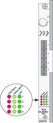
| LED | LED Color | Description |
|---|---|---|
|
Red Alarm |
Red (ON) OFF |
Illuminates when the port is in a fault condition, such as LOS or LOF. Off when there is no alarm for this port. |
|
Yellow Alarm |
Yellow (ON) OFF |
Illuminates when the port is receiving a signal indicating a problem at the remote end, for example, RDI. Off when there is no alarm for this port. |
|
Link |
Green (On) Yellow (On) OFF |
Illuminates Green when a fiber optic cable is plugged into the port and the receive signal is detected by the SFP module. Illuminates Yellow when an SFP module is plugged into the port. Off indicates that there is no SFP module plugged into the port. |
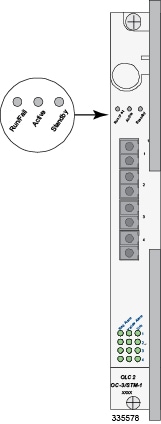
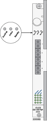
Card-Level LEDs on the Channelized (STM-1/OC-3) Line Card
Each Channelized line card (CLC2) is equipped with card-level status LEDs:
-
Run/Fail
-
Active
-
Standby
The location of these LEDs is displayed in the figure below. The various states are described in the following three tables.
- Channelized Line Card Run/Fail LED States
- Channelized Line Card Active LED States
- Channelized Line Card Standby LED States
Channelized Line Card Run/Fail LED States
The Run/Fail LED on the Channelized line card indicates the overall status of the card. These LEDs are illuminated steady green during normal operation.
| Color | Description | Troubleshooting |
|---|---|---|
|
Green |
Card powered with no errors detected |
None needed. |
|
Red |
Card powered with error(s) detected |
Errors were detected during the POSTs. It is likely that the errors were logged to the system's command line interface during the boot process. |
|
None |
Card is not receiving power |
Verify that the POWER LEDs on the PFUs are green. If they are not, refer to Checking the LED on the PFU for troubleshooting information. |
|
Verify that the power source is supplying ample voltage and current to the chassis. |
||
|
Verify that the card is properly installed per the instructions in this document. |
||
|
If all of the above suggestions have been verified, it is possible that the line card is not functional. Please contact your service representative. |
Channelized Line Card Active LED States
The Active LED on the channelized line card indicates that the operating software is loaded on the card and that the card is ready for operation.
Installed line cards remain in ready mode until their corresponding packet processing card is activated during configuration. While in ready mode the Active LED is off. After the packet processing card is activated, the line card installed in the upper-rear chassis slot behind the packet processing card is also activated. The line card installed in the lower-rear chassis slot behind the packet processing card enters standby mode.
| Color | Description | Troubleshooting |
|---|---|---|
|
Green |
Card is active |
None needed for line cards installed in slots 17 through 23 and 26 through 32 after configuration. If green for line cards in slots 33 through 39 and 42 through 48, verify that the corresponding line card installed in the upper-rear chassis slot is installed properly according to the instructions in this document. For example, if this LED is green for a line card in slot 33, verify that the line card in slot 17 is installed properly. |
|
None |
Card in Ready Mode OR Card is not receiving power OR Card in Standby Mode |
This is normal prior to configuration. Neither the Active or the Standby LED on the card will be on. |
|
Verify that the Run/Fail LED is green. If so, the card is receiving power and POST test results are positive. If it is off, refer to Channelized Line Card Run/Fail LED States for troubleshooting information. |
||
|
Check the state of the Standby LED. If it is green, the card is in standby mode. Refer to the System Administration Guide for information on making the card active. |
Channelized Line Card Standby LED States
The Standby LED on the channelized line card indicates that software is loaded on the card and it is serving as a redundant component.
The installed line cards remain in ready mode until their corresponding packet processing card is activated via configuration. While in ready mode, the Active LED is off. After the packet processing card is activated, the line card installed in the upper-rear chassis slot behind the packet processing card is activated. The line card installed in the lower-rear chassis slot behind the packet processing card enters standby mode.
| Color | Description | Troubleshooting |
|---|---|---|
|
Green |
Card is in redundant mode |
None needed for line cards installed in slots 33 through 39 and 42 through 48 after configuration. If green for line cards installed in slots 17 through 23 and 26 through 32, refer to the System Administration Guide for troubleshooting information. |
|
None |
Card in Ready Mode OR Card is not receiving power OR Card in Active Mode |
This is normal prior to configuration. Neither the Active nor Standby LEDs on the card will be on. |
|
Verify that the Run/Fail LED is green. If so, the card is receiving power and POST test results are positive. If it is off, refer to Channelized Line Card Run/Fail LED States for troubleshooting information. |
||
|
Check the state of the Active LED. If it is green, the card is in standby mode. |
Checking the Alarm and Link LEDs on the Channelized Line Card 2
Each CLC2 provides alarm and link LEDs that indicate the status of each port. These LEDs are located at the bottom of the front panel, as illustrated in the figure below.
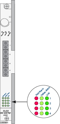
| LED | LED Color | Description |
|---|---|---|
|
Red Alarm |
Red (ON) OFF |
Illuminates when the port is in a fault condition, such as LOS or LOF. Off when there is no alarm for this port. |
|
Yellow Alarm |
Yellow (ON) OFF |
Illuminates when the port is receiving a signal experiences a problem at the remote end, such as RDI. Off when there is no alarm for this port. |
|
Link |
Green (ON) Yellow (ON) OFF |
Illuminates Green when a fiber optic cable is plugged into the port and the receive signal is detected by the SFP module. Illuminates Yellow when an SFP module is plugged into the port. Off indicates that there is no SFP module plugged into the port. |
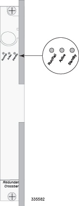
Checking the LEDs on the RCC(s)
Each RCC is equipped with status LEDs shown in the following figure:
The possible states for all of the SPIO's LEDs are described in the sections that follow.
RCC Run/Fail LED States
The RCC Run/Fail LED indicates the overall status of the card. This LED is illuminated steady green during normal operation.
| Color | Description | Troubleshooting |
|---|---|---|
|
Green |
Card powered with no errors detected |
None needed. |
|
Red |
Card powered with error(s) detected |
Errors were detected during the POSTs. It is likely that the errors were logged to the system's command line interface during the boot process. |
|
None |
Card powered with error(s) detected |
Verify that the POWER LEDs on the PFUs are green. If they are not, refer to Checking the LED on the PFU for troubleshooting information. |
|
Verify that the power source is supplying ample voltage and current to the chassis. |
||
|
Verify that the card is properly installed per the instructions in this document. |
||
|
If all of the above suggestions have been verified, it is possible that the RCC is not functional. Please contact your service representative. |
RCC Active LED States
The Active LED on the RCC indicates that the card is being used. During normal operation, this LED is off on both RCCs.
| Color | Description | Troubleshooting |
|---|---|---|
|
Green |
Card is active |
The RCC is actively routing traffic from a line card installed behind a packet processing card that has failed to a redundant packet processing card. The RCC installed in chassis slot 40 processes traffic for the line cards in chassis slots 17 through 23 and 26 through 32. The RCC installed in chassis slot 41 processes traffic for the line cards in slots 33 through 39 and 42 through 48. See Checking the LEDs on Packet Processing Cards to determine which packet processing card has failed. Information on determining the cause of the failure can be found in the System Administration Guide. |
|
None |
Card is not receiving power OR Card in Standby Mode |
Verify that the Run/Fail LED is green. If so, the card is receiving power and POST test results are positive. If it is off, refer to RCC Run/Fail LED States for troubleshooting information. |
|
Check the state of the Standby LED. If it is green, the card is in standby mode. This is the normal operating mode. |
RCC Standby LED States
The Standby LED on the RCC indicates that software is loaded on the card. The card is ready to provide a path for data or signalling traffic from a line card to a redundant packet processing card. This LED is on during normal operation for both installed RCCs.
| Color | Description | Troubleshooting |
|---|---|---|
|
Green |
Card is in standby mode |
This is the normal operating mode. |
|
None |
Card is not receiving power OR Card in Active Mode |
Verify that the Run/Fail LED is green. If so, the card is receiving power and POST test results are positive. If it is off, refer to RCC Run/Fail LED States for troubleshooting information. |
|
Check the state of the Active LED. If it is green, the card is in active mode and the RCC is actively routing traffic from a line card installed behind a packet processing card that has failed. See Checking the LEDs on Packet Processing Cards to determine which packet processing card has failed. |
Completing Initial System Configuration
After power is applied to the chassis and the ASR 5000 has successfully booted, the command line interface (CLI) appears on a terminal connected to the Console port of the SPIO.
Configuring the system for remote access
Configuring the management interface with a second IP Address (optional)
Configuring system timing
Enabling CLI timestamping
Configuring system administrative users
Configuring TACACS+ for system administrative users (optional)
Configuring a chassis key
Configuring virtual MAC addresses
Configuring packet processing and line card availability
Configuring line card and SPIO port redundancy
Configuring ASR 5000 link aggregation (optional)
Configuring ORBEM and the Web Element Manager (optional)
Configuring SNMP support and trap generation
The Getting Started, Configuring System Settings and Configuring Management Settings chapters of the System Administration Guide provide detailed procedures for completing the above tasks.
 Feedback