- About this Guide
- ASR 5000 Hardware Platform Overview
- Installation Procedure Overview
- Chassis Installation
- Application Card Installation
- Line Card Installation
- Cabling the Switch Processor Input/Output Line Card
- Cabling the Fast Ethernet (10/100) Line Card
- Cabling the Gigabit Ethernet Line Cards
- Cabling the Optical (ATM) Line Cards
- Cabling the Channelized Line Cards
- Cabling the Power Filter Units
- Applying Power and Verifying the Installation
- System Monitoring
- Adding Application and Line Cards to an Existing Installation
- Removing and Installing SMC PC Cards
- Replacing the Chassis Air Filter
- Replacing a Power Filter Unit
- Replacing Upper or Lower Fan Tray
- Replacing Application Cards
- Replacing Line Cards
- Technical Specifications
- Safety, Electrical and EMC Certifications
- Environmental Specifications
- Hardware Product Support Matrix
- Preparing a Full-Height Line Card Slot
- RMA Shipping Procedures
- Spare Component Recommendations
Cabling the Gigabit Ethernet Line Cards
This chapter provides cabling instructions and information for the interfaces on the Gigabit Ethernet Line Card (GLC2), the four-port Quad Gigabit Ethernet Line Card (QGLC), and 10 Gigabit Ethernet Line Card (XGLC).
These cards support 802.3z-compliant Gigabit Ethernet interface(s) which connect the chassis to other elements in the packet data network.
This chapter includes the following sections:
- Gigabit Ethernet Line Card (GLC2)
- Quad Gigabit Ethernet Line Card (QGLC)
- RJ-45 SFP Module Detail
- Cabling the Optical SFP+ Interface
- 10 Gigabit Ethernet Line Card (XGLC)
- Cabling the Optical SFP+ Interface
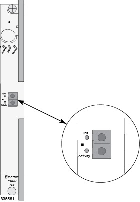
Gigabit Ethernet Line Card (GLC2)
The following figure shows the single-port GLC2. The front panel of this card is labeled "Ethernet 1000". This card supports a single fiber or copper Small Form-factor Plugin (SFP) transceiver module as described below:
The following SFP modules are hot-pluggable.
| Module Type | Card Identification | Interface Type | Cable Specifications |
|---|---|---|---|
|
1000Base-SX |
Ethernet 1000 SX |
Fiber, LC duplex female connector |
Fiber Type: Multi-mode fiber (MMF), 850 nm wavelength
Minimum Tx Power: -9.5 dBm Rx Sensitivity: -17 dBm |
|
1000Base-LX |
Ethernet 1000 LX |
Fiber, LC duplex female connector |
Fiber Type: Single-mode fiber (SMF), 1310 nm wavelength Core Size (microns)/Range: 9/32808.4 feet (10 Kilometers) Minimum Tx Power: -9.5 dBm Rx Sensitivity: -19 dBm |
|
1000Base-T |
Ethernet 1000 Copper |
RJ-45 |
Operates in full-duplex up to 100 meters of CAT-5 shielded twisted pair (STP) cable with BER less than 10e-10. NOTE: To comply with GR-1089 intra-building, lightning-immunity requirements and ensure compliance with Radiated Emissions Criteria, you must use shielded-twisted pair cable and ensure that it is properly terminated at both ends. |
The SFP interface is only certified to work with SFP transceiver modules purchased from Cisco for use with the GLC2.
Class 1 Laser Compliance Notice
Because of the optical SFP interface, this product has been tested and found to comply with the limits for Class 1 laser devices for IEC825, EN60825, and 21CFR1040 specifications.
Quad Gigabit Ethernet Line Card (QGLC)
The following figure shows the four-port Quad Gigabit Ethernet Line Card (QGLC). The front panel of this card is labeled "Ethernet 1000".
If you enter the show card table CLI command, the QGLC is listed as a Quad 1000 Ethernet Line Card.
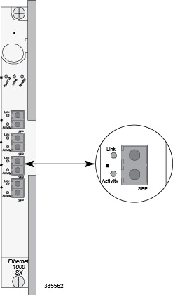
The QGLC supports four fiber or copper SFP transceiver modules as described below. The modules are hot-pluggable. However, they must all be the same type. You cannot mix-and-match SFP modules in one QGLC.
| Module Type | Card Identification | Interface Type | Cable Specifications |
|---|---|---|---|
|
1000Base-SX |
Ethernet 1000 SX |
Fiber, LC duplex female connector |
Fiber Type: Multi-mode fiber (MMF), 850 nm wavelength Minimum Tx Power: -9.5 dBm Rx Sensitivity: -17 dBm |
|
1000Base-LX |
Ethernet 1000 LX |
Fiber, LC duplex female connector |
Fiber Type: Single-mode fiber (SMF), 1310 nm wavelength Core Size (microns)/Range: 9/32808.4 feet (10 Kilometers) Minimum Tx Power: -9.5 dBm Rx Sensitivity: -19 dBm |
|
1000Base-T |
Ethernet 1000 Copper |
RJ-45 |
Operates in full-duplex up to 100 meters of CAT-5 shielded twisted pair (STP) cable with BER less than 10e-10. NOTE: To comply with GR-1089 intra-building, lightning-immunity requirements and ensure compliance with Radiated Emissions Criteria, you must use shielded-twisted pair cable and ensure that it is properly terminated at both ends. |
The SFP interface is only certified to work with SFP transceiver modules purchased from Cisco for use with the QGLC.
Because of the optical SFP interface, this product has been tested and found to comply with the limits for Class 1 laser devices for IEC825, EN60825, and 21CFR1040 specifications.
RJ-45 SFP Module Detail
The following describes the RJ-45 (copper) SFP module for the GLC2 and the QGLC with pinouts and definitions.
To comply with GR-1089 intra-building, lightning-immunity requirements and ensure compliance with FCC Radiated Emissions Criteria, you must use shielded-twisted pair (STP) cable and assure that it is properly terminated at both ends.
The 1000Base-TX interface is suitable for connection to intra-building or unexposed wiring or cabling only. These intra-building ports MUST NOT be metallically connected to interfaces that connect to the outside plant (OSP) or its wiring. These interfaces are designed for use as intra-building interfaces only (Type 2 or Type 4 ports as described in GR-1089-CORE, Issue 5) and require isolation from the exposed OSP cabling. The addition of Primary Protectors is not sufficient protection in order to connect these interfaces metallically to OSP wiring.
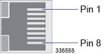
| Pin | 1000Base-Tx 1Gbps Cat5+ |
|---|---|
|
1 |
BI DA+ |
|
2 |
BI DA- |
|
3 |
BI DB+ |
|
4 |
BI DC+ |
|
5 |
BI DC- |
|
6 |
BI DB- |
|
7 |
BI DD+ |
|
8 |
BI DD- |
|
RX = Receive Data TX = Transmit Data BI = BI directional data DA, DB, DC, DD = Data Pair A, B, C, and D |
|
Cabling the Optical SFP+ Interface
To interconnect the optical SFP+ interface on the XGLC, follow the instructions below.
Be sure to label the interface cable with its destination prior to connecting it to the XGLC. This will assure proper reconnection should the card need to be serviced.
 Note | Only trained and qualified personnel should install, replace, or service this equipment. |
Note | Invisible laser radiation may be emitted from the aperture of the port when no cable is connected. Avoid exposure to laser radiation and do not look into open apertures. Be sure to keep the cover on the interface when it is not in use. |
Note | Laser Klasse 1 - nur speziell ausgebildetes Personal darf dieses Geraet warten. Nicht in den Laser schauen, um Augenverletzungen zu vermeiden. Nicht genutzte Buchsen mit der entsprechenden Kappe verschliessen. |
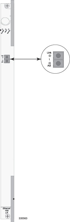
10 Gigabit Ethernet Line Card (XGLC)
The 10 Gigabit Ethernet Line Card or XGLC, is a full-height line card. The XGLC uses industry standard SFP+ transceiver modules to support various fiber types as required. The following diagram shows the XGLC's single SFP+ interface.
| Module Type | Card Identification | Interface Type | Cable Specifications |
|---|---|---|---|
|
10G Base-SR |
Ethernet 10G SR |
Fiber, LC duplex female connector |
Fiber Type: Multi-mode fiber (MMF), 850 nm wavelength
Minimum Tx Power: -7.3 dBm Rx Sensitivity: -11.1 dBm |
|
10G Base-LR |
Ethernet 10G LR |
Fiber, LC duplex female connector |
Fiber Type: Single-mode fiber (SMF), 1310 nm wavelength Core Size (microns)/Range: 9/32808.4 feet (10 Kilometers) Minimum Tx Power: -11.0 dBm Rx Sensitivity: -19 dBm |
XGLCs can be installed in chassis slots 17 through 23 and 26 through 32. These cards should always be installed directly behind their respective PSCs, PSC2s, or PPCs, but they are not required behind any redundant packet processing cards (those operating in Standby mode).
-
Link: This green LED shows whether or not the line card is connected to the network. The LED is illuminated when the card is connected.
-
Activity: This green LED shows when data is transmitted or received. The LED is illuminated when data is passing through the interface.
Because of the optical SFP interface, this product has been tested and found to comply with the limits for Class 1 laser devices for IEC825, EN60825, and 21CFR1040 specifications.
Cabling the Optical SFP+ Interface
To interconnect the optical SFP+ interface on the XGLC, follow the instructions below.
Be sure to label the interface cable with its destination prior to connecting it to the XGLC. This will assure proper reconnection should the card need to be serviced.
Note | Only trained and qualified personnel should install, replace, or service this equipment. |
Note | Invisible laser radiation may be emitted from the aperture of the port when no cable is connected. Avoid exposure to laser radiation and do not look into open apertures. Be sure to keep the cover on the interface when it is not in use. |
Note | Laser Klasse 1 - nur speziell ausgebildetes Personal darf dieses Geraet warten. Nicht in den Laser schauen, um Augenverletzungen zu vermeiden. Nicht genutzte Buchsen mit der entsprechenden Kappe verschliessen. |
 Feedback