- About this Guide
- ASR 5000 Hardware Platform Overview
- Installation Procedure Overview
- Chassis Installation
- Application Card Installation
- Line Card Installation
- Cabling the Switch Processor Input/Output Line Card
- Cabling the Fast Ethernet (10/100) Line Card
- Cabling the Gigabit Ethernet Line Cards
- Cabling the Optical (ATM) Line Cards
- Cabling the Channelized Line Cards
- Cabling the Power Filter Units
- Applying Power and Verifying the Installation
- System Monitoring
- Adding Application and Line Cards to an Existing Installation
- Removing and Installing SMC PC Cards
- Replacing the Chassis Air Filter
- Replacing a Power Filter Unit
- Replacing Upper or Lower Fan Tray
- Replacing Application Cards
- Replacing Line Cards
- Technical Specifications
- Safety, Electrical and EMC Certifications
- Environmental Specifications
- Hardware Product Support Matrix
- Preparing a Full-Height Line Card Slot
- RMA Shipping Procedures
- Spare Component Recommendations
Environmental Specifications
This chapter provides information related to environmental considerations and storage characteristics associated with the ASR 5000.
It includes the following sections:
Operating and Storage Parameters
Use the following information to plan your network installation for the ASR 5000 platform.
| Temperature | |
|
Operating |
0 degrees C to +55 degrees C (32 degrees F to +130 degrees F) |
|
Storage |
-40 degrees C to +70 degrees C (-40 degrees F to +158 degrees F) |
| Humidity | |
|
Operating |
20 to 80 percent non-condensing |
|
Storage |
10 to 95 percent non-condensing |
| Altitude | |
|
Operating |
197 ft. (60m) below to 13,123 ft. (4,000m) above sea level |
|
Non-operating |
197 ft. (60m) below to 49,212 ft. (15,000m) above sea level |
Supported Environmental Standards
Operational Thermal, Operating Conditions - GR-63 Criteria [72, 73]
Airborne Contaminants, Indoor Levels - GR-63 Criterion [125]
Operational Thermal, Short-term Conditions - GR-63 Criteria [72, 73]
Storage Environments, and Transportation and Handling - GR-63 Criteria [69-71, 107-109, 124]
Earthquake Zone 4 - GR-63 Criteria [110-112, 114, 115, 117, 119]
Airborne Contaminants, Outdoor Levels - GR-63 Criteria [126, 127]
Altitude - GR-63 Criteria [74, 76]
Thermal Heat Dissipation - GR-63 Criteria [77-79]
Acoustic Noise - GR-63 Criterion [128]
ESTI 300 019 - Environmental conditions and environmental tests for telecommunications equipment
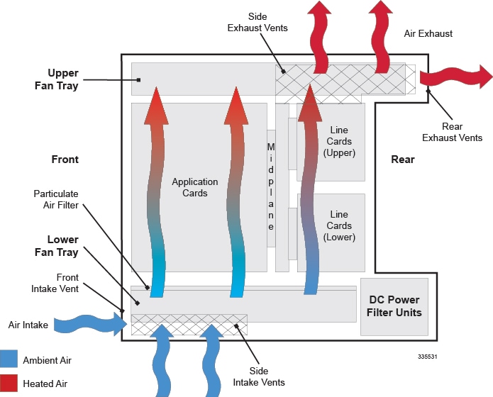
Chassis Air Flow
Airflow within the ASR 5000 is designed per Telcordia recommendations to ensure the proper vertical convection cooling of the system.
As shown in the figure below, the lower fan tray pulls ambient air into the chassis from the front and side intake vents located at the bottom of the chassis. The air is pushed upwards through the system and absorbs heat while passing over system components.
 Caution | When planning chassis installation, ensure that equipment rack or cabinet hardware does not hinder air flow at any of the intake or exhaust vents. Additionally, ensure that the rack/cabinet hardware, as well as the ambient environment, allow the system to function within the operating limits specified in this chapter. |
 Feedback