- About this Guide
- ASR 5000 Hardware Platform Overview
- Installation Procedure Overview
- Chassis Installation
- Application Card Installation
- Line Card Installation
- Cabling the Switch Processor Input/Output Line Card
- Cabling the Fast Ethernet (10/100) Line Card
- Cabling the Gigabit Ethernet Line Cards
- Cabling the Optical (ATM) Line Cards
- Cabling the Channelized Line Cards
- Cabling the Power Filter Units
- Applying Power and Verifying the Installation
- System Monitoring
- Adding Application and Line Cards to an Existing Installation
- Removing and Installing SMC PC Cards
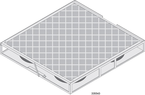
- Replacing the Chassis Air Filter
- Replacing a Power Filter Unit
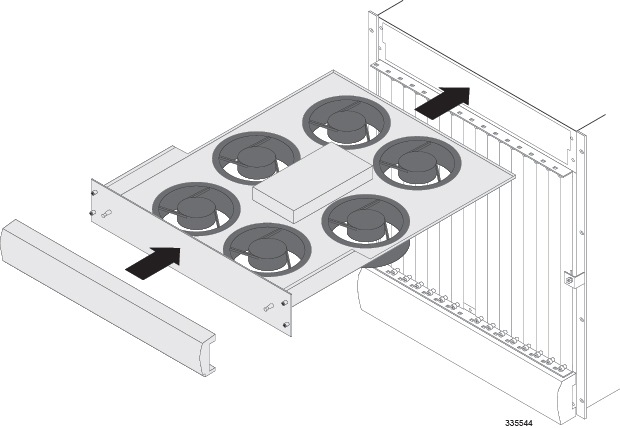
- Replacing Upper or Lower Fan Tray
- Replacing Application Cards
- Replacing Line Cards
- Technical Specifications
- Safety, Electrical and EMC Certifications
- Environmental Specifications
- Hardware Product Support Matrix
- Preparing a Full-Height Line Card Slot
- RMA Shipping Procedures
- Spare Component Recommendations
Chassis Installation
This chapter provides information on rack configurations and instructions for installing and removing the chassis and its sub-components – the upper and lower fan trays and the Power Filter Units (PFUs).
Prior to installation, personnel should review and be familiar with all recommendations for Central Office installations, as found in Telcordia GR-1275-CORE Central Office Environment Installation/Removal Generic Requirements, Issue 3, December 2001.
This chapter includes the following sections:
- Equipment Rack Configuration
- Weight Considerations
- Unpacking the ASR 5000 Chassis
- Installing the Chassis
Equipment Rack Configuration
The chassis is designed for installation in a standard 19-inch (48.26 cm) equipment rack. Additional rack hardware, such as extension brackets, may be used to install the chassis in a standard 23-inch (58.42 cm) rack. Each chassis is 24.50 inches (62.23 cm) high. This equates to roughly 14 Rack Mount Units (RMUs: 1 RMU = 1.75 in (4.45 cm).
You can mount a maximum of three chassis in a standard 48 RMU (7 ft.) equipment rack or telco cabinet provided that all system cooling and ventilation requirements are met. A fully-loaded rack with three chassis installed has approximately 5.5 inches (13.97 cm, 3.14 RMUs) of vertical space remaining.
 Caution | When planning chassis installation, take care to ensure that the equipment rack or cabinet hardware does not hinder air flow at any of the intake or exhaust vents. Additionally, ensure that the environmental control system (HVAC) allows the system to function within the required limits. |
Ventilation Considerations
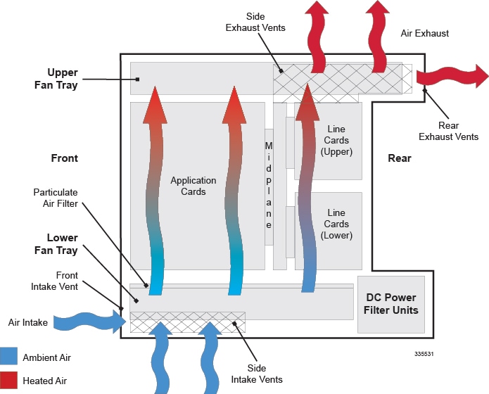
Airflow within the system is designed per Telcordia recommendations to ensure the proper vertical convection cooling of the system.
As shown in the figure below, the lower fan tray pulls ambient air inward from the front and side intake vents located at the bottom of the chassis. The air is pushed upwards through the system and absorbs heat as it passes over system components.
The upper fan tray pulls the heated air up through the chassis. The heated air exits through the side and rear exhaust vents located at the top of the chassis.
|
Operating Temperature |
0 degrees C to +55 degrees C 32 degrees F to +131 degrees F |
|
Operating Humidity |
20 percent to 80 percent, non-condensing |
Mounting Options
There are two options for mounting the chassis in a standard equipment rack or telecommunications cabinet:
-
Flush Mount: In this configuration, the flanges of the mounting brackets are flush with the front of the chassis. This is the default configuration as shipped as is commonly used with 4-post racks and equipment cabinets. Refer to Flush Mount Installation of the Chassis.
-
Mid-mount: In this configuration, the flanges of the mounting brackets are recessed from the front of the chassis. This configuration is required when mounting the chassis in a 2-post rack. To do this, install the mounting brackets toward the middle of the chassis on either side. Refer to Mid-Mount Installation of the Chassis.
Weight Considerations
The shipping weight of the chassis is approximately 160 pounds (72.57 kg). Please consider the following recommendations before proceeding:
-
If available, use an equipment lift to lift and move the chassis during the installation process.
-
If no lift is available, reduce the weight according to the instructions in the Reducing the Weight of the Chassis Prior to Installation. These procedures reduces the weight of the chassis to approximately 125 lbs. (56.7 kg).
-
At least two people are required to perform the installation. These individuals should be physically able to lift and control the weight of the chassis.
-
When lifting any heavy object, it is important to remember to bend at the knees and lift with your legs. Bending at the waist and lifting with your back could cause personal injury.
Unpacking the ASR 5000 Chassis
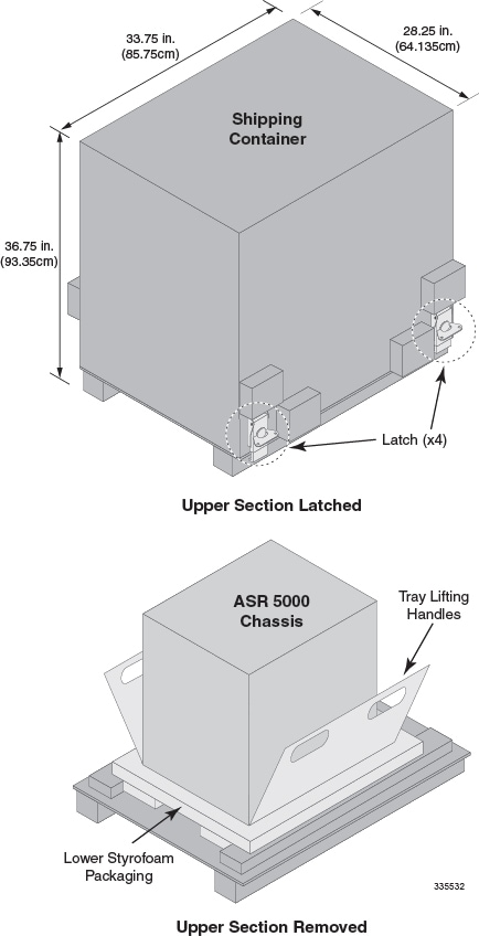
Before unpacking the chassis, use a pallet jack to move the container as close to the final installation site as possible.
The chassis ships in a wooden container that is 28.25 in. (64.135cm) wide by 36.75 in. (93.35cm) high by 33.75 in. (85.75cm) deep. The container consists of an upper and lower section. The upper section forms the sides and top of the container. The lower section serves as the bottom of the container. The upper and lower sections are secured together for shipping via four locking mechanisms located near the bottom corners of the container.
Refer to the printed instructions that come with the shipment for detailed unpacking procedures.
Installing the Chassis
If you are installing more than one chassis in an equipment rack, to ensure an easier installation, begin by installing the first chassis near the bottom of the rack.
Caution | When handling or moving the chassis, lift the chassis from the bottom only. Lifting it by any other part could result in damage to the chassis. |
Caution | During installation, maintenance, and/or removal, wear grounding wrist and/or heel straps to avoid ESD damage to the components. Failure to do so could result in damage to sensitive electronic components and potentially void your warranty. |
- Reducing the Weight of the Chassis Prior to Installation
- Flush Mount Installation of the Chassis
- Mid-Mount Installation of the Chassis
- Grounding the Chassis
- Re-Installing Chassis Sub-components
Reducing the Weight of the Chassis Prior to Installation
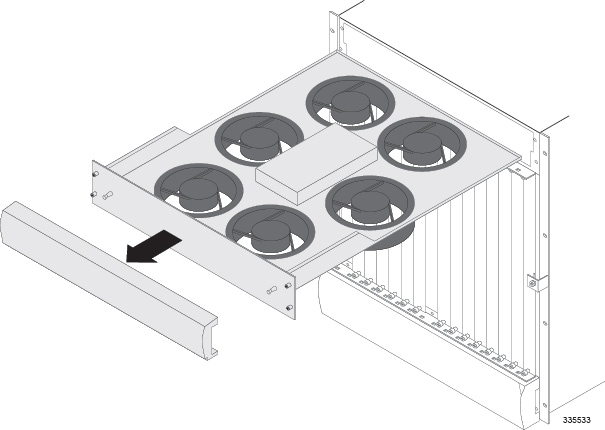
To make the installation process easier, you can reduce the weight of the chassis prior to installation by removing the upper and lower fan trays and the PFUs. Follow the instructions below to safely remove these components prior to installation.
Caution | During installation, maintenance, and/or removal, wear grounding wrist and/or heel straps to avoid ESD damage to the components. Failure to do so could result in damage to sensitive electronic components and potentially void your warranty. |
| Step 1 | Remove the upper
fan tray.
|
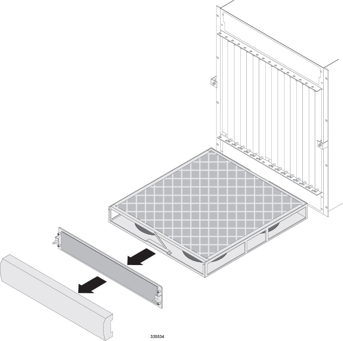
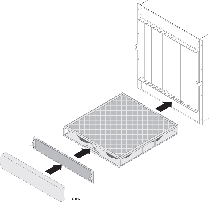
| Step 2 | Remove the lower
fan tray assembly.
|
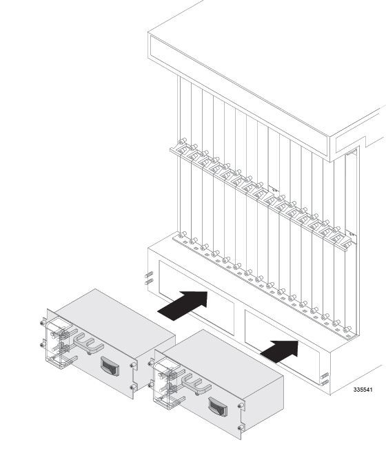
| Step 3 | Remove the PFUs
located in the lower-rear of the chassis.
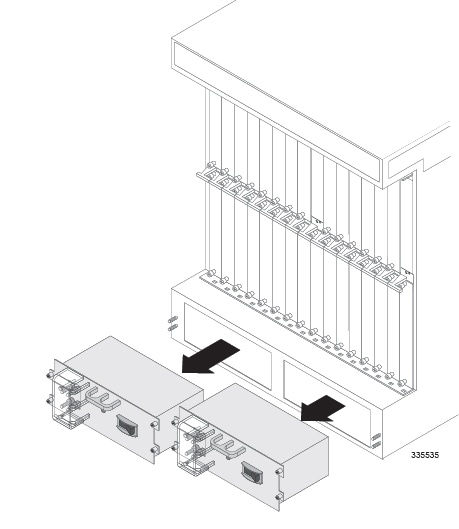
|
| Step 4 | Proceed to either the Flush Mount Installation of the Chassis or Mid-Mount Installation of the Chassis, based on the mounting option you are using. |
Flush Mount Installation of the Chassis
Follow the instructions below to perform the flush mount installation of the chassis.
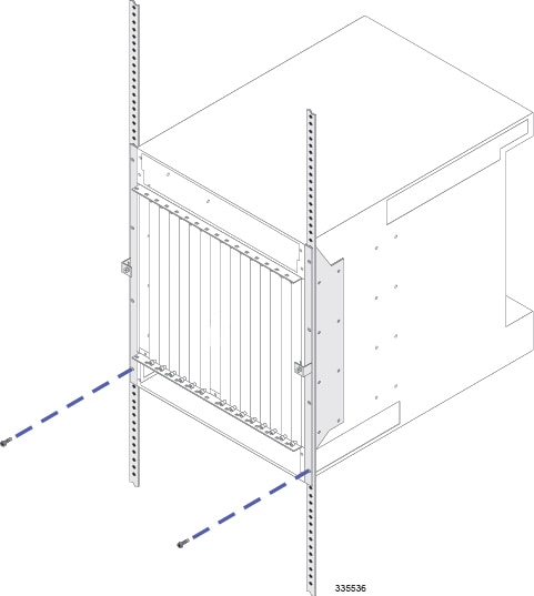
| Step 1 | Position the chassis in the equipment rack so that the flanges of the mounting brackets at the front of the chassis are flush with the mounting rails of the equipment rack. |
| Step 2 | Mount the
chassis to the rails of the equipment rack. Use the hardware that was supplied
with the equipment rack. Begin with the two bottom holes and work your way up
until all four holes on each flange are secured.
|
| Step 3 | Repeat step 1 and step 2 for any additional chassis you are installing in the equipment rack. |
| Step 4 | Proceed to the Grounding the Chassis section and ground the chassis. |
Mid-Mount Installation of the Chassis
Follow the instructions below to perform the mid-mount installation of the system.
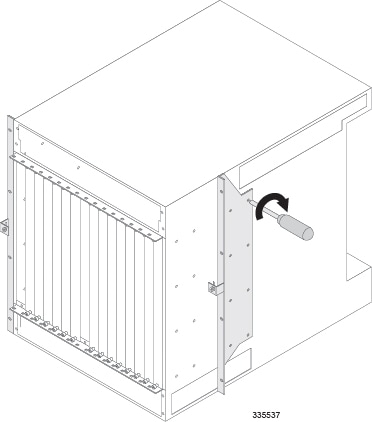
| Step 1 | On the side of the chassis, unfasten the eight Phillips #2 screws that secure the mounting bracket to the chassis. |
| Step 2 | Place the
mounting bracket over the middle set of mounting holes on the side of the
chassis and secure it to the chassis with the screws you removed in step 1.
|
| Step 3 | Repeat step 1 and step 2 for the bracket on the opposite side of the chassis. |
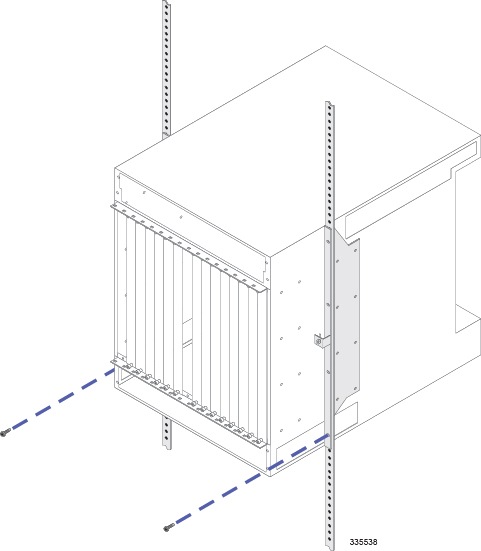
| Step 4 | Position the chassis in the equipment rack so that the flanges of the mounting brackets are flush with the mounting rails of the equipment rack. |
| Step 5 | Mount the
chassis to the rails of the equipment rack with the hardware that was supplied
with the equipment rack. Begin with the two bottom holes and work your way up
until all holes on each flange are secured.
|
| Step 6 | Repeat step 1 through step 5 for any additional chassis you are installing in the equipment rack. |
| Step 7 | Proceed to the Grounding the Chassis and ground the chassis. |
Grounding the Chassis
Make sure that the chassis is properly grounded prior to installing any chassis sub-components or cards. The chassis and the equipment rack or telecommunications cabinet that it is installed in must be connected to the same ground.
Caution | Failure to properly ground the chassis could result in personal injury and/or damage to the chassis and its components. |
There are two sets of grounding terminals located at the lower-rear of the chassis. The following figure and the table that follows show the location of these terminals and provide specifications for the appropriate lug and cable size.
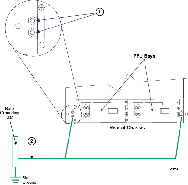
| Item | Description |
|---|---|
|
1 |
Ground Terminal: 2-hole lug (0.186-inch posts, spaced 0.630-inch on center). The method of connection is: chassis - lug - flat washer - nut (3/8-inch). The nut(s) must be torqued to 50 in-lb (5.65 N-m). |
|
2 |
Ground Cable: Cable length: Not more than 70 feet (21.336 meters) one way. Cable size: 6 AWG (minimum), stranded copper. |
Follow the instructions below to connect the chassis to earth ground.
| Step 1 | Locate the chassis ground terminal on the lower-left corner of the rear of the chassis next to Power Filter Unit 1. |
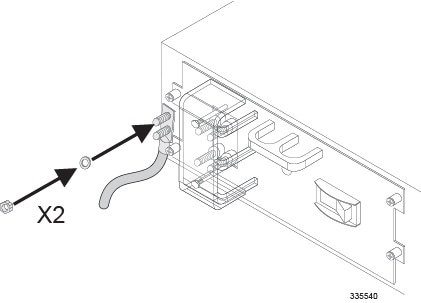
| Step 2 | Route the stranded copper ground cable to the chassis ground terminal. |
| Step 3 | Crimp a 2-hole lug (Panduit type LCC6-10A-L) to the end of the ground cable using Panduit crimp tool part number CT-1700 (die color: blue 24). |
| Step 4 | Use a 3/8-inch nut driver or socket wrench to remove the nuts and washers from each of the two posts. |
| Step 5 | Insert the lug connected to the grounding cable over the two posts. |
| Step 6 | Secure the lug
to the ground terminals with the nuts and washers you removed in step 4. The
nuts should be torqued to 50 in-lb (5.65 N-m).
|
| Step 7 | Repeat step 2 through step 6 to connect the second ground cable to the chassis ground terminal on the lower-right corner at the rear of the chassis next to Power Filter Unit 2. |
| Step 8 | If you took steps to reduce the weight of the chassis prior to installation, refer to the instructions in the Re-Installing Chassis Sub-components to re-install the components. Otherwise, proceed to the Application Card Installation chapter. |
Re-Installing Chassis Sub-components
If you performed the procedure in the Reducing the Weight of the Chassis Prior to Installation section, complete the procedures described below to re-install the sub-components of the chassis.
Caution | During installation, maintenance, and/or removal, wear grounding wrist straps to avoid ESD damage to the components. Failure to do so could result in damage to sensitive electronic components and potentially void your warranty. |
 Feedback