- About this Guide
- ASR 5000 Hardware Platform Overview
- Installation Procedure Overview
- Chassis Installation
- Application Card Installation
- Line Card Installation
- Cabling the Switch Processor Input/Output Line Card
- Cabling the Fast Ethernet (10/100) Line Card
- Cabling the Gigabit Ethernet Line Cards
- Cabling the Optical (ATM) Line Cards
- Cabling the Channelized Line Cards
- Cabling the Power Filter Units
- Applying Power and Verifying the Installation
- System Monitoring
- Adding Application and Line Cards to an Existing Installation
- Removing and Installing SMC PC Cards
- Replacing the Chassis Air Filter
- Replacing a Power Filter Unit
- Replacing Upper or Lower Fan Tray
- Replacing Application Cards
- Replacing Line Cards
- Technical Specifications
- Safety, Electrical and EMC Certifications
- Environmental Specifications
- Hardware Product Support Matrix
- Preparing a Full-Height Line Card Slot
- RMA Shipping Procedures
- Spare Component Recommendations
Cabling the Fast Ethernet (10/100) Line Card
This chapter provides information on the Fast Ethernet Line Card (FLC2) interfaces and instructions for installing the cables.
This chapter includes the following section:
FLC2 Interfaces
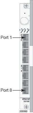
The Fast Ethernet Line Card (FLC2, Ethernet 10/100) has eight RJ-45 interfaces, as shown in the figure below. Each of these is an auto-sensing 10Base-T/100Base-TX Ethernet interface that terminates a shielded twisted-pair (STP) copper cable. The interfaces are labeled 1 through 8 from top to bottom.
To comply with GR-1089 intra-building, lightning-immunity requirements and ensure compliance with FCC Radiated Emissions Criteria, you must use shielded-twisted pair (STP) cable and ensure that it is properly terminated at both ends.
The 10/100Base-TX ports of the FLC2 are suitable for connection to intra-building or unexposed wiring or cabling only. These intra-building ports MUST NOT be metallically connected to interfaces that connect to the outside plant (OSP) or its wiring. These interfaces are designed for use as intra-building interfaces only (Type 2 or Type 4 ports as described in GR-1089-CORE, Issue 5) and require isolation from the exposed OSP cabling. The addition of Primary Protectors is not sufficient protection in order to connect these interfaces metallically to OSP wiring.
The system uses these interfaces to connect to other elements in the packet data network.
Refer to the following figure and table for pinouts for the RJ-45 Ethernet ports.
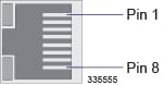
| Pin | 100Base-T 100Mbps Cat5 |
|---|---|
|
1 |
TX+ |
|
2 |
TX- |
|
3 |
RX+ |
|
4 |
Not applicable |
|
5 |
Not applicable |
|
6 |
RX- |
|
7 |
Not applicable |
|
8 |
Not applicable |
|
RX = Receive Data TX = Transmit Data |
|
Be sure to label the interface cables with their destinations prior to connecting them to the FLC2. This will assure proper reconnection should the card need to be serviced.
To cable the FLC2, simply plug an STC Ethernet cable from a network device into the desired port.
 Feedback