- About this Guide
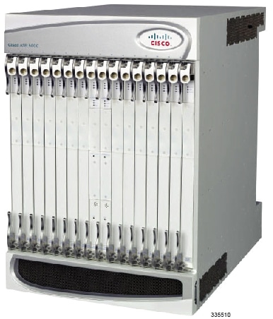
- ASR 5000 Hardware Platform Overview
- Installation Procedure Overview
- Chassis Installation
- Application Card Installation
- Line Card Installation
- Cabling the Switch Processor Input/Output Line Card
- Cabling the Fast Ethernet (10/100) Line Card
- Cabling the Gigabit Ethernet Line Cards
- Cabling the Optical (ATM) Line Cards
- Cabling the Channelized Line Cards
- Cabling the Power Filter Units
- Applying Power and Verifying the Installation
- System Monitoring
- Adding Application and Line Cards to an Existing Installation
- Removing and Installing SMC PC Cards
- Replacing the Chassis Air Filter
- Replacing a Power Filter Unit
- Replacing Upper or Lower Fan Tray
- Replacing Application Cards
- Replacing Line Cards
- Technical Specifications
- Safety, Electrical and EMC Certifications
- Environmental Specifications
- Hardware Product Support Matrix
- Preparing a Full-Height Line Card Slot
- RMA Shipping Procedures
- Spare Component Recommendations
ASR 5000 Hardware Platform Overview
This chapter describes the hardware components that comprise the ASR 5000.
It includes the following sections:
- The ASR 5000 Platform
- Chassis Configurations
- Chassis Description
- Power Filter Units
- Fan Tray Assemblies
- Application Cards
- Line Cards
- Card Interlock Switch
- Card Identifiers
The ASR 5000 Platform
The ASR 5000 multimedia core platform is designed for deployment in multimedia-enabled core networks. It features a distributed architecture that allows all tasks and services to be allocated across the entire platform. This platform allows operators to deploy more efficient mobile networks that support a greater number of concurrent calls, optimize resource usage, and deliver enhanced services, while providing scalability.
ASR 5000 hardware components support the following features:
Chassis Configurations
The system is designed to scale from a minimum configuration, as shown in the table below, to a fully-loaded redundant configuration containing a maximum of 48 cards.
If session recovery is enabled, the minimum number of packet processing cards per chassis increases from one to four cards. Three packet processing cards are active and one packet processing card is standby (redundant). This minimal configuration is designed to protect against software failures only.
| Component | Supported ASR 5000 Product | Redundant HW Configuration (Note 1) | Redundant HW + SW Configuration (Note 2) | Maximum per Chassis |
|---|---|---|---|---|
| Application Cards | ||||
| System Management Card (SMC) | All | 2 | 2 | 2 |
| Packet Services Card (PSC) | End of Life (not supported in Release 16.0+) | |||
| Packet Services Card Type A (PSCA) | End of Life (not supported in Release 16.0+) | |||
| Packet Services Card 2 (PSC2) | All |
3 (2 active +1 standby) |
4 (3 active +1 standby) See Note 3 below. |
14 |
| Packet Services Card 3 (PSC3) | ||||
| Packet Processing Card (PPC) | End of Life (not supported in Release 16.0+) | |||
| Chassis Subcomponents | ||||
| Power Filter Unit (PFU) | All | 2 | 2 | 2 |
| Upper Fan Tray Assembly | All | 1 | 1 | 1 |
| Lower Fan Tray Assembly | All | 1 | 1 | 1 |
| Line Cards | ||||
| Switch Processor I/O (SPIO) Card | All | 2 | 2 | 2 |
| Redundancy Crossbar Card (RCC) | All | 2 | 2 | 2 |
| Fast Ethernet Line Card (FELC) | End of Life (replaced by FLC2) | |||
| Fast Ethernet Line Card 2 (FLC2) | All | 2 | See Note 4 below. | 28* |
| Gigabit Ethernet Line Card (GELC) | End of Life (replaced by GLC2) | |||
| Gigabit Ethernet Line Card 2 (GLC2) | All | 2 | See Note 4 below. | 28* |
| Quad Gigabit Ethernet Line Card (QGLC) | All | 2 | 28* | |
| 10 Gigabit Ethernet Line Card (XGLC) | All | 2 | 14** | |
| Optical Line Card 2 (OLC2) | SGSN only | 2 | 28* | |
| Channelized Line Card 2 (CLC2) | SGSN only | 2 | 28* | |
Notes:
1. These numbers represent the minimum number of components for hardware redundancy. Additional components are required if Session Recovery is to be supported.
2. These numbers represent the minimum number of components for: a) hardware and software redundancy; b) platforms with combined services. Additional components are required if Session Recovery is to be supported.
3. This is the minimum configuration for redundant SGSN service and MME service.
4. This number varies based on network deployment requirements.
*The maximum number of half-height line cards you can install is 28. However, redundant configurations may use fewer than the physical maximum number of line cards since they are inactive behind standby packet service cards.
**The 10 Gigabit Ethernet Line Card (XGLX) is a full-height line card that takes up the upper and lower slots in the back of the chassis. When referring to an installed XGLC, use the upper slot number only. Slot numbering for other installed half-height cards is maintained: 17 to 32 and 33 to 48, regardless of the number of installed XGLCs.
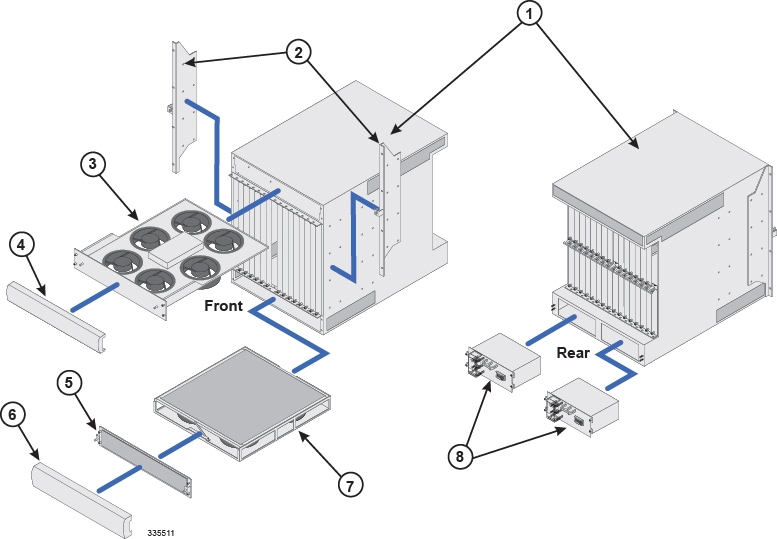
| Item | Description |
|---|---|
| 1 | Chassis: Supports 16 front-loading slots for application
cards and 32 rear-loading slots for line cards. To support the XGLC, a
full-height line card, remove the half-height guide from the rear slots.
The chassis ships with blanking panels over every slot except the following: 1, 8, 17, and 24. These are intentionally left uncovered for initial installation of application and line cards. |
| 2 | Mounting brackets: Support installation in a standard 19-inch rack or telecommunications cabinet. Flush and mid-mount options are supported. In addition, each bracket contains an electrostatic discharge jack for use when handling equipment. |
| 3 | Upper fan tray: Draws air through the chassis for cooling and ventilation. It then exhausts warmed air through the vents at the upper-rear of the chassis. |
| 4 | Upper bezel: Covers the upper fan tray bay. |
| 5 | Lower fan tray cover/EMI shield: Secures the lower fan tray assembly in place and serves as an EMI shield. The cover also provides an air baffle allowing air to enter into the chassis. |
| 6 | Lower bezel: Covers the lower fan tray bay. |
| 7 | Lower fan tray assembly: Draws ambient air through the chassis' front and sides for cooling and ventilation. It is equipped with a particulate air filter to prevent dust and debris from entering the system. |
| 8 | Power Filter Units (PFUs): Each of the system's two PFUs provides -48 VDC power to the chassis and its associated cards. Each load-sharing PFU operates independently of the other to ensure maximum power feed redundancy. |
Chassis Description
Slot Numbering
The ASR 5000 chassis features a 48-slot design with 16 front-loading slots for application cards and 32 rear-loading slots (16 upper and 16 lower) for line cards. ASR 5000.
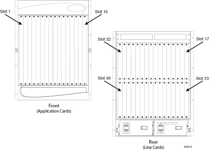
| Position | Slot Number | |||||||||||||||
|---|---|---|---|---|---|---|---|---|---|---|---|---|---|---|---|---|
| Front | 16 | 15 | 14 | 13 | 12 | 11 | 10 | 9 | 8 | 7 | 6 | 5 | 4 | 3 | 2 | 1 |
| Rear Top Slots | 32 | 31 | 30 | 29 | 28 | 27 | 26 | 25 | 24 | 23 | 22 | 21 | 20 | 19 | 18 | 17 |
| Rear Bottom Slots | 48 | 47 | 46 | 45 | 44 | 43 | 42 | 41 | 40 | 39 | 38 | 37 | 36 | 35 | 34 | 33 |
Rear Slot Numbering for Half-Height Line Cards
Rear-installed line cards must be installed directly behind their respective front-loaded application card. For example, an application card in Slot 1 must have a corresponding line card in Slot 17. The redundant line card for this configuration would be placed in Slot 33. This establishes a directly mapped communication path through the chassis midplane between the application and line cards.
To help identify which rear slot corresponds with the front-loaded application card, the upper rear slot numbers are equal to the slot number of the front-loaded card plus 16. For example, to insert a line card to support an application card installed in slot 1, add 16 to the slot number of the front-loaded application card (Slot 1 + 16 slots = Slot 17). Slot 17 is the upper right-most slot on the rear of the chassis, directly behind Slot 1.
For lower rear slot numbers, add 32. Again, a redundant line card for an application card in Slot 1 would be (Slot 1 + 32 = Slot 33). Slot 33 is the lower right-most slot on the rear of the chassis, also behind Slot 1.
Rear Slot Numbering with Full-height Line Cards
ASR 5000 systems may be configured with 10 Gigabit Ethernet Line Cards (XGLCs). These are full-height line cards that require the removal of the half-height card guides to accommodate the cards. In this case, only the upper slot number is used to refer to the XGLC. For half-height cards installed with the XGLCs, the half-height slot numbering scheme is maintained.
For example, XGLCs installed in slots 17 and 32 also take up slots 33 and 48, but are referred to as cards in slots 17 and 32 only. The slots in which the SPIOs and RCCs are installed in the same configuration, are slots 24 and 25, and 40 and 41, respectively.
Mounting Options
The chassis is designed for installation in a standard (EIA-310-D, IEC 60297) 19-inch wide (482.6 mm) equipment rack or telco cabinet. Additional rack hardware (such as extension brackets) may be used to install the chassis in a 23-inch (584.2 mm) rack. Each chassis is 24.50 inches (62.23 cm) high. This equates to 14 Rack Units (1 RU = 1.75 in. [44.5 mm]).
You can mount a maximum of three ASR 5000 chassis in a 2- or 4-post equipment rack, or telco cabinet, provided that all system cooling and ventilation requirements are met. Three stacked chassis will occupy a minimum of 42 RUs.
Flush mount: In this configuration, the flanges of the mounting brackets are flush with the front of the chassis. This method is typically used with 4-post racks and telco equipment cabinets. This is the default configuration as shipped.
Mid-mount: In this configuration, the flanges of the mounting brackets are recessed from the front of the chassis. This method is typically used with 2-post racks. You must remove and re-install the mounting brackets in the middle of the chassis on both sides.
 Caution | The equipment rack or cabinet hardware must not hinder air flow at any of the intake or exhaust vents. The ambient environment (conditioned space) must allow the system to function within its specified operating limits. |
Midplane Architecture
The midplane separates the front and rear chassis slots. The connectors on the midplane provide intra-chassis communications, power connections, and data transport paths between the various installed cards.
The midplane also contains two independent -48 VDC busses (not shown) that distribute redundant power to each card within the chassis.
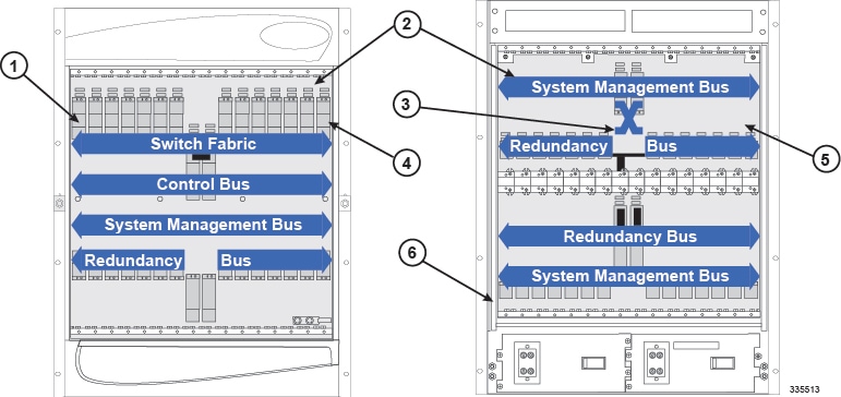
| Item | Description |
|---|---|
| 1 | Slot number 1 (left-most application card slot) |
| 2 | Chassis midplane: provides intra-chassis communications and data transport paths between the various installed cards |
| 3 | SPIO cross-connect bus |
| 4 | Chassis slot number 16: right-most application card slot |
| 5 | Chassis slot number 17: upper right-most line card slot. The 10 Gigabit Ethernet Line Card (XGLC) is a full-height line card that takes up the upper and lower slots in the back of the chassis. Use the upper slot number only when referring to installed XGLCs. Slot numbering for other half-height lines cards is maintained: 17 to 32 and 33 to 48, regardless of the number of installed XGLCs. |
| 6 | Chassis slot number 48: lower left-most line card slot |
The following subsections describe each bus.
- 320 Gbps Switch Fabric
- 32 Gbps Control Bus
- System Management Bus
- 280 Gbps Redundancy Bus
- OC-48 TDM Bus
- SPIO Cross-Connect Bus
320 Gbps Switch Fabric
The System Management Card (SMC) is an IP-based (packetized) switch fabric that provides a transport path for user data throughout the system. Its 320 Gbps switch fabric establishes inter-card communication between the SMCs and other application cards within the chassis along with their associated line cards.
32 Gbps Control Bus
The Control Bus features redundant 32 Gbps Ethernet paths that interconnect all control and management processors within the system. The bus uses a full-duplex Gigabit Ethernet (GigE) switching hierarchy from both SMCs to each of the 14 application card slots in the chassis. Each application card is provisioned with a GigE switch to meet its specific needs. This bus also interconnects the two SMC modules.
System Management Bus
The System Management Bus supports management access to each component within the chassis. It provides a communication path from each SMC to every card in the system with a 1 Mbps transfer rate to each card. This allows the SMCs to manage several low-level system functions (such as, supplying power, monitoring temperature, board status, pending card removals, data path errors, redundant/secondary path switchovers, card resets and failovers). Additionally, the System Management Bus monitors and controls the fan trays, PFUs, and alarming functions.
280 Gbps Redundancy Bus
The Redundancy Bus consists of multiple, full-duplex serial links providing packet processing card-to-line card redundancy through the chassis' Redundancy Crossbar Cards (RCCs) as shown below.
Each serial link facilitates up to 5 Gbps symbol rate, equivalent to 4 Gbps of user data traffic, in each direction. Therefore, the Redundancy Bus provides 140 Gbps symbol rate (112 Gbps user data) of throughput per RCC, 280 Gbps symbol rate (224 Gbps user data) total for both.
OC-48 TDM Bus
The system also hosts a dual OC-48 TDM bus consisting of 128 independent TDM paths each consisting of 512 DS0 channels. This bus supports voice services on the system. Higher speed TDM traffic requirements are addressed using the system's data fabric.
SPIO Cross-Connect Bus
To provide redundancy between Switch Processor I/O (SPIO) cards, the system possesses a physical interconnect between the ports on the SPIOs. This cross-connect allows management traffic or alarm outputs to be migrated from an active SPIO experiencing a failure to the redundant SPIO.
While an SPIO should be installed directly behind its corresponding SMC, this bus allows either SMC to utilize either SPIO.
Power Filter Units
Located at the bottom rear of the chassis are slots for two 165-amp Power Filter Unit (PFU) assemblies. Each PFU provides DC power from the site's power distribution frame (PDF) to the chassis and its associated cards. Each load-sharing PFU operates independently of the other to ensure maximum power feed redundancy. The maximum input operating voltage range of the PFU is -40 VDC to -60 VDC; the nominal range is -48 VDC to -60 VDC.
The ASR 5000 does not offer an AC power supply option. If only AC power is available at the installation site, an adequately sized AC-to-DC converter will be required to supply -48 VDC power to the chassis.
The following drawing shows the PFU and its connectors.
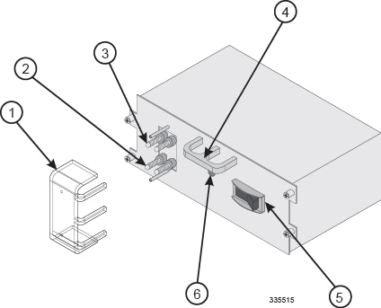
| Item | Description |
|---|---|
| 1 | Plastic terminal cover |
| 2 | VDC (-48 VDC input terminals) |
| 3 | RTN (voltage return terminals) |
| 4 | PFU handle |
| 5 | Circuit breaker (On/Off) rated at 165A |
| 6 | Power LED |
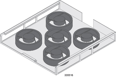
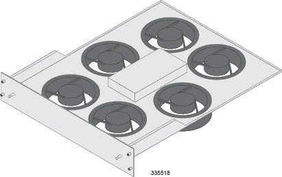
Fan Tray Assemblies
There are two fan tray assemblies within the chassis. A lower fan tray intakes ambient air and an upper fan tray exhausts warmed air from the chassis. Each fan tray is connected to both PFUs to ensure power feed redundancy. Both fan tray assemblies are variable speed units that automatically adjust fan speed based on temperature or failover situations.
Thermal sensors monitor temperatures within the chassis. In the event of a fan failure or other temperature-related condition, the SMC notifies all operable fans in the system to switch to high speed, and generates an alarm.
Lower Fan Tray
The lower fan tray assembly contains multiple fans and pulls ambient air into the chassis from the lower front and sides of the chassis. The air is then pushed upward across the cards and midplane to support vertical convection cooling.
Air Filter Assembly
The chassis supports a replaceable particulate air filter that meets UL 94-HF-1 standards for NEBS-compliant electronics filtering applications. This filter mounts above the lower fan tray assembly and removes contaminants before they enter the system. Temperature sensors measure the temperature at various points throughout the chassis. The system monitors this information, and generates a maintenance alarm, if necessary.
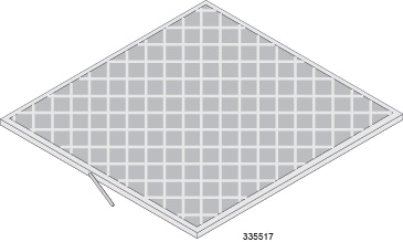
A replacement air filter is shipped with each chassis. A minimum of one replacement air filter for each deployed chassis should be kept on site. This allows qualified service personnel to quickly replace the filter when necessary.
Upper Fan Tray
The upper fan tray unit contains multiple fans that exhaust air from the upper rear and sides of the chassis.
Chassis Airflow
Airflow within the chassis complies with Telcordia recommendations to ensure proper vertical convection cooling of the system.
Application Cards
The following application cards are supported by the system.
System Management Card (SMC)
The SMC serves as the primary system controller, initializing the entire system and loading the software's configuration image into other cards in the chassis as applicable.
SMCs are installed in the chassis slots 8 and 9. During normal operation, the SMC in slot 8 serves as the primary card and the SMC in slot 9 serves as the secondary. Each SMC has a dual-core central processing unit (CPU) and 4 GB of random access memory (RAM).
There is a single PC-card slot on the front panel of the SMC that supports removable ATA Type I or Type II PCMCIA cards. Use these cards to load and store configuration data, software updates, buffer accounting information, and store diagnostic or troubleshooting information.
There is also a Type II CompactFlash™ slot on the SMC that hosts configuration files, software images, and the session limiting/feature use license keys for the system.
-
Non-blocking low latency inter-card communication
-
1:1 or 1:N redundancy for hardware and software resources
-
System management control
-
Persistent storage via CompactFlash and PCMCIA cards (for field serviceability), and a hard disk drive for greater storage capabilities
-
Internal gigabit Ethernet switch fabrics for management and control plane communication
The front panel of the SMC with its major components is shown below:
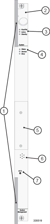
| Item | Description |
|---|---|
| 1 | Card Ejector Levers —Use to insert/remove card to/from chassis. |
| 2 | Interlock Switch —Sliding this switch downward on an active SMC initiates an immediate switchover to the standby SMC. |
| 3 | Card Level Status LEDs—Show the status of the card. See Applying Power and Verifying Installation for definitions. |
| 4 | System Level Status LEDs—Show the status of overall system health and/or maintenance requirements. See Applying Power and Verifying Installation for definitions. |
| 5 | PC-Card/PCMCIA Slot—Stores or moves software, diagnostics, and other information. |
| 6 | System Alarm Speaker—Sounds an audible alarm when specific system failures occur. |
| 7 | Alarm Cut-Off (ACO) —Press and release this recessed toggle switch to reset the system alarm speaker and other audible or visual alarm indicators connected to the CO Alarm interface on the SPIO. |
SMC RAID Support
Each SMC is equipped with a hard disk, commonly referred to as a Small Form Factor (SFF) disk.
The hard disk is not physically accessible. Disk failure constitutes an SMC failure.
If there is a redundant SMC in the chassis, the standby disk mirror the disk in the active SMC, forming an active Redundant Array of Inexpensive Disks (RAID).
HD RAID ids configurable via CLI commands. RAID control mechanisms allow xDR charging data to be written to the hard disks on both the active and standby SMCs for later upload to a suitable local or remote storage server.
Event logs related to disk and RAID include disk name, serial number and RAID UUID for reference. They are generated at the Critical, Error, Warning, and Informational levels.
RAID failure, including failures during runtime and various cases of initial RAID discovery and disk partition failures
File system failure when the system fails to initialize or mount file systems
Network failure for NFS server-related errors
RAID disk failure, including failures during runtime
Internal errors, including forking process failures
Overwriting a valid or invalid disk partition, RAID image, and file system
RAID construction in progress and possible failure
Low disk space
Files deleted to free up disk space
Disk partition completion
RAID discovery results without overwriting
RAID construction completion
RAID disk added or removed
File system initialization
NFS service start
Files copied/removed from CDR module to RAID disk
The hard disk supports SNMP notifications which are described in the SNMP MIB Reference.
When the hard-disk is filled, dynamically created records files in the folder /hd-raid/record will be deleted to free up space. Other user-created files on the disk should be cleaned up manually.
Packet Processing Cards: PSC2 and PSC3
The packet processing cards provide packet processing and forwarding capabilities within a system. Each card type supports multiple contexts, which allows an operator to overlap or assign duplicate IP address ranges in different contexts.
Caution | You cannot mix packet processing card types in the same chassis. |
Specialized hardware engines support parallel distributed processing for compression, classification, traffic scheduling, forwarding, packet filtering, and statistics.
- Provides "Fast-path" processing of frames using hardware classifiers to determine each packet's processing requirements
- Receives and transmits user data frames to and from various physical interfaces
- Performs IP forwarding decisions (both unicast and multicast)
- Provides per interface packet filtering, flow insertion, deletion, and modification
- Manages traffic and traffic engineering
- Modifies, adds, or strips datalink/network layer headers
- Recalculates checksums
- Maintains statistics
- Manages both external line card ports and the internal connections to the data and control fabrics
To take advantage of the distributed processing capabilities of the system, you can add packet processing cards to the chassis without their supporting line cards, if desired. This results in increased packet handling and transaction processing capabilities. Another advantage is a decrease in CPU utilization when the system performs processor-intensive tasks such as encryption or data compression.
Packet processing cards can be installed in chassis slots 1 through 7 and 10 through 16. Each card can either Active (available to the system for session processing) or redundant (a standby component available in the event of a failure).
The front panel of a packet processing card with its major components is shown below.
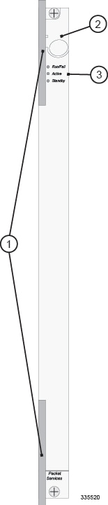
| Item | Description |
|---|---|
| 1 | Card Ejector Levers —Use to insert/remove card to/from chassis. |
| 2 | Interlock Switch —In its Down position the interlock switch notifies the system to safely power down the card prior to its removal. |
| 3 | Card Level Status LEDs —Show the current status of the card. See Applying Power and Verifying Installation for definitions. |
| 4 | Card Identification Label —Indicates the type of packet processing card. See the table at the end of this chapter. |
- Packet Services Card (PSC)
- Packet Services Card Type A (PSCA)
- Packet Services Card 2 (PSC2)
- Packet Services Card 3 (PSC3)
- Packet Processor Card (PPC) Description
Packet Services Card (PSC)
The PSC has reached its end of life and is no longer available for purchase. It is not supported in StarOS Release 16.0 and higher.
Packet Services Card Type A (PSCA)
The PSCA has reached its end of life and is no longer available for purchase. It is not supported in StarOS Release 16.0 and higher.
Packet Services Card 2 (PSC2)
The PSC2 uses a fast network processor unit, featuring two quad-core x86 CPUs and 32 GB of RAM. These processors run a single copy of the operating system. The operating system running on the PSC2 treats the two dual-core processors as a 4-way multi-processor.
The PSC2 has a dedicated security processor that provides the highest performance for cryptographic acceleration of next-generation IP Security (IPSec), Secure Sockets Layer (SSL) and wireless LAN/WAN security applications with the latest security algorithms.
PSC2s should not be mixed with PSC3s. Due to the different processor speeds and memory configurations, the PSC2 cannot be combined in a chassis with other packet processing card types.
The PSC2 can dynamically adjust the line card connection mode to support switching between XGLCs and non-XGLCs with minimal service interruption.
PSC2 is fully redundant with a spare PSC2.
Packet Services Card 3 (PSC3)
The PSC3 provides increased aggregate throughput and performance and a higher number of subscriber sessions than the PSC2. Specialized hardware engines support parallel distributed processing for compression, classification, traffic scheduling, forwarding, packet filtering, and statistics.
The PSC3 features two 6-core CPUs and 64 GB of RAM. These processors run a single copy of the operating system. The operating system running on the PSC3 treats the two core processors as a 6-way multi-processor.
To optimize network efficiency and minimize down time, the system supports 1:n redundancy for PSC3s. If session recovery is enabled, the minimum number of PSC3s per chassis increases from one to four cards. Three PSC3s are active and one PSC3 is standby (redundant). This minimum configuration protects against software failures only. In addition to increased hardware requirements, Session Recovery may reduce subscriber session capacity, performance, and data throughput.
In the event of PSC3 failure, tasks are migrated from the active PSC3 to the standby card. The line card installed behind the PSC3 that was formerly active maintains the interfaces to the external network equipment. Redundancy Crossbar Cards (RCCs) provide a path for signaling and data traffic between the line card and the now active packet processing card.
PSC3s must not be mixed with PSC2s.
The PSC3 is fully redundant with a spare PSC3.
Packet Processor Card (PPC) Description
The PSCA has reached its end of life and is no longer available for purchase. It is not supported in StarOS Release 16.0 and higher.
Line Cards
The following rear-loaded cards are currently supported by the system.
- Switch Processor I/O (SPIO) Card
- Redundancy Crossbar Card (RCC)
- Fast Ethernet Line Card (FLC2)
- Gigabit Ethernet Line Card (GLC2)
- Quad Gigabit Ethernet Line Card (QGLC)
- 10 Gigabit Ethernet Line Card (XGLC)
- Optical Line Card (OLC2)
- Channelized Line Card (CLC2)
Switch Processor I/O (SPIO) Card
The SPIO card provides connectivity for local and remote management, CO alarming, and Building Integrated Timing Supply (BITS) timing input. SPIOs are installed in chassis slots 24 and 25, behind SMCs. During normal operation, the SPIO in slot 24 works with the active SMC in slot 8. The SPIO in slot 25 serves as a redundant component. In the event that the SMC in slot 8 fails, the redundant SMC in slot 9 becomes active and works with the SPIO in slot 24. If the SPIO in slot 24 should fail, the redundant SPIO in slot 25 takes over.
The following shows the front panel of the SPIO card, its interfaces, and other major components.
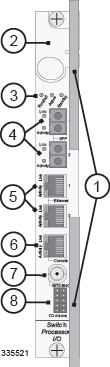
| Item | Description |
|---|---|
| 1 | Card Ejector Levers—Use to insert/remove card to or from the chassis. |
| 2 | Interlock Switch—In its Down position the interlock switch notifies the system to safely power down the card prior to its removal. |
| 3 | Card Level Status LEDs—Show the status of the card. See Applying Power and Verifying Installation for definitions. |
| 4 | Optical Gigabit Ethernet Management LAN Interfaces—Two Small Form-factor Pluggable (SFP) optical Gigabit Ethernet interfaces to connect optical transceivers. |
| 5 | 10/100/1000 Mbps Ethernet Management LAN Interfaces—Two RJ-45 interfaces, supporting 10/100 Mbps or 1 Gbps Ethernet. |
| 6 | Console Port—RJ-45 interface used for local connectivity to the command line interface (CLI). See Cabling the Switch Processor Input/Output Line Card for more information. |
| 7 | BITS Timing Interface (Optional) —Either an analog E1 BNC coaxial connector or T1 (DS-1) 3-pin wire-wrap connector. Used for application services that use either the OLC2 or CLC2 line cards. |
| 8 | CO Alarm Interface—Dry contact relay switches, allowing connectivity to central office, rack, or cabinet alarms. See Applying Power and Verifying Installation for more information. |
Management LAN Interfaces
SPIO management LAN interfaces connect the system to the carrier's management network and applications, normally located remotely in a Network Operations Center (NOC). You can use the RJ-45 copper 10/100/1000 Mbps Ethernet interfaces or optical SFP Gigabit Ethernet interfaces to connect to the management network.
When using the RJ-45 interfaces, use CAT5 shielded twisted pair (STP) cabling.
Use shielded cabling whenever possible to further protect the chassis and its installed components from ESD or other transient voltage damage.
| Module Type | Card Identification | Interface Type | Cable Specifications |
|---|---|---|---|
| 1000Base-SX | Ethernet 1000 SX | Fiber, LC duplex female connector | Fiber Type: Multi-mode fiber (MMF), 850 nm wavelength
Minimum Tx Power: -9.5 dBm Rx Sensitivity: -17 dBm |
Console Port
The console uses an RS-232 serial communications port to provide local management access to the command line interface (CLI). A 9-pin-to-RJ-45 console cable is supplied with each SPIO card. The console cable must provide carrier-detect when attached in a null modem configuration.
Should connection to a terminal server or other device requiring a 25-pin D-subminiature connector be required, a specialized cable can be constructed to support DB-25 to RJ-45 connectivity. The baud rate for this interface is configurable between 9600 bps and 115,200 bps (default is 9600 bps).
BITS Timing
The Building Integrated Timing Supply (BITS) timing interface is optional and required only when the system is used in support of non-data applications. A BITS module is available on two versions of the SPIO: one supports an analog E1 BNC coaxial interface (for 2048 kHZ clocking), and the other a T1 (DS1) 3-pin wire-wrap interface (for 1544 kHz clocking).
If your system is equipped with OLC2 or CLC2 line cards for SDH/SONET, you can configure it to derive system clocking from a port on either card. This functionality requires that the SPIO includes the optional Stratum 3 clocking module to distribute clocking to all line cards in the chassis.
Central Office Alarm Interface
The CO alarm interface is a 10-pin connector for up to three dry-contact relay switches for connection to a CO alarm monitoring panel. The three Normally Closed alarm relays can be wired to support Normally Open or Normally Closed devices, indicating minor, major, and critical alarms.
A CO alarm cable is shipped with the product so you can connect the CO Alarm interfaces on the SPIO card to your alarming devices. The "Y" cable design ensures CO alarm redundancy by connecting to both primary and secondary SPIO cards.
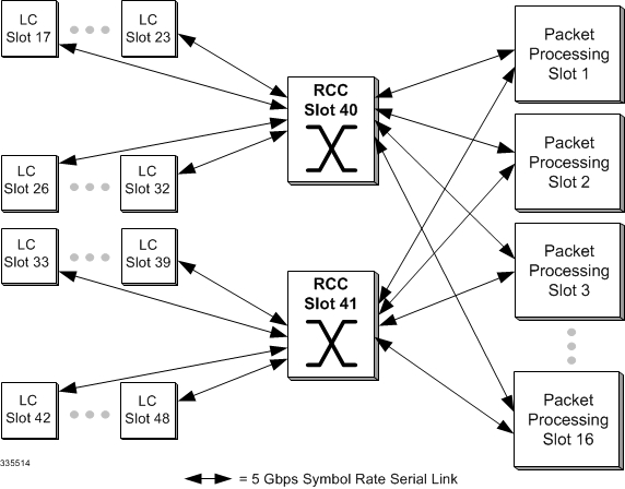
Redundancy Crossbar Card (RCC)
The RCC uses 5 Gbps serial links to ensure connectivity between rear-mounted line cards and every non-SMC front-loaded application card slot in the system. This creates a high availability architecture that minimizes data loss and ensures session integrity. If a packet processing card were to experience a failure, IP traffic would be redirected to and from the LC to the redundant packet processing card in another slot. Each RCC connects up to 14 line cards and 14 packet processing cards for a total of 28 bidirectional links or 56 serial 2.5 Gbps bidirectional serial paths.
The RCC provides each packet processing card with a full-duplex 5 Gbps link to 14 (of the maximum 28) line cards placed in the chassis. This means that each RCC is effectively a 70 Gbps full-duplex crossbar fabric, giving the two RCC configuration (for maximum failover protection) a 140 Gbps full-duplex redundancy capability.
The RCC located in slot 40 supports line cards in slots 17 through 23 and 26 through 32 (upper rear slots). The RCC in slot 41 supports line cards in slots 33 through 39 and 42 through 48 (lower rear slots):
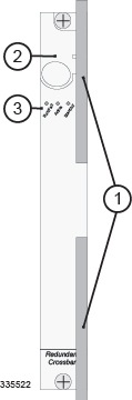
| Item | Description |
|---|---|
| 1 | Card Ejector Levers—Use to insert/remove a card to and from the chassis. |
| 2 | Interlock Switch—In its Down position the interlock switch notifies the system to safely power down the card prior to its removal. |
| 3 | Card Level Status LEDs—Show the status of the card. |
Fast Ethernet Line Card (FLC2)
The FLC2 installs directly behind its respective packet processing card, providing network connectivity to the RAN interface and the packet data network. Each FLC2 (Ethernet 10/100) has eight RJ-45 interfaces. Each of these IEEE 802.3-compliant interfaces supports auto-sensing 10/100 Mbps Ethernet. Allowable cabling includes:
The FELC has reached its end of life and is no longer available for purchase. It has been replaced by the FLC2.
Use shielded cabling whenever possible to further protect the chassis and its installed components from ESD or other transient voltage damage.
The FLC2 supports the Star Channel (1 Gbps) for faster FPGA upgrades and is Restriction of Hazardous Substances (RoHS) 6/6 compliant.
The FLC2 can be installed in chassis slots 17 through 23, 26 through 39, and 42 through 48. These cards are always installed directly behind their respective packet processing cards, but are not required to be placed behind any redundant packet processing cards (those operating in Standby mode).
The following shows the panel of the FLC2 with its interfaces and major components.
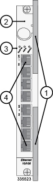
| Item | Description |
|---|---|
| 1 | Card Ejector Levers—Use to insert/remove card to/from chassis. |
| 2 | Interlock Switch—In its Down position the interlock switch notifies the system to safely power down the card prior to its removal. |
| 3 | Card Level Status LEDs—Show the status of the card. |
| 4 | RJ-45 10/100 Ethernet Interfaces—Eight auto-sensing RJ-45 interfaces for R-P interface connectivity carrying user data. Ports are numbered 1 through 8 from top to bottom. |
Gigabit Ethernet Line Card (GLC2)
The GLC2 installs directly behind its respective packet processing card, providing network connectivity to the packet data network. The GLC2 (Ethernet 1000) supports a variety of 1000 Mbps optical and copper interfaces based on the type of Small Form-factor Pluggable (SFP) modules installed on the card.
The GELC has reached its end of life and is no longer available for purchase. It has been replaced by the GLC2.
| Module Type | Card Identification | Interface Type | Cable Specifications |
|---|---|---|---|
| 1000Base-SX | Ethernet 1000 SX | Fiber, LC duplex female connector |
Fiber Type: Multi-mode fiber (MMF), 850 nm wavelength Minimum Tx Power: -9.5 dBm Rx Sensitivity: -17 dBm |
| 1000Base-LX | Ethernet 1000 LX | Fiber, LC duplex female connector |
Fiber Type: Single-mode fiber (SMF), 1310 nm wavelength Core Size (microns)/Range: 9/32808 feet (10 kilometers) Minimum Tx Power: -9.5 dBm Rx Sensitivity: -19 dBm |
| 1000Base-T | Ethernet 1000 Copper | RJ-45 |
Operates in full-duplex up to 100 meters of CAT-5 Shielded Twisted Pair (STP) cable with BER less than 10e-10. |
This product has been tested and found to comply with the limits for Class 1 laser devices for IEC825, EN60825, and 21CFR1040 specifications.
The GLC2 supports the Star Channel (1 Gbps) for faster FPGA upgrades and is Restriction of Hazardous Substances (RoHS) 6/6 compliant.
The GLC2s can be installed in chassis slots 17 through 23, 26 through 39, and 42 through 48. These cards are always installed directly behind their respective or packet processing cards, but they are not required behind any redundant packet processing cards (those operating in Standby mode).
The following diagram shows the front panel of the GLC2 with an optical connector, identifying its interfaces and major components.
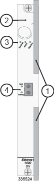
| Item | Description |
|---|---|
| 1 | Card Ejector Levers—Use to insert/remove card to/from chassis. |
| 2 | Interlock Switch—In its Down position, the interlock switch notifies system to safely power down card prior to removal. |
| 3 | Card Level Status LEDs—Show the status of the card. See Applying Power and Verifying Installation for definitions. |
| 4 |
Gigabit Ethernet Interface—Gigabit Ethernet (GE) SFP modules. 1000Base-SX, 1000Base-LX, and 1000Base-T interfaces are supported depending on the SFP module installed. |
Quad Gigabit Ethernet Line Card (QGLC)
The QGLC is a 4-port Gigabit Ethernet line card that installs directly behind its associated packet processing card to provide network connectivity to the packet data network. There are several different versions of Small Form-factor Pluggable (SFP) modules available for the QGLC.
| Module Type | Card Identification | Interface Type | Cable Specifications |
|---|---|---|---|
| 1000Base-SX | Ethernet 1000 SX | Fiber, LC duplex female connector |
Fiber Type: Multi-mode fiber (MMF), 850 nm wavelength Minimum Tx Power: -9.5 dBm Rx Sensitivity: -17 dBm |
| 1000Base-LX | Ethernet 1000 LX | Fiber, LC duplex female connector |
Fiber Type: Single-mode fiber (SMF), 1310 nm wavelength Core Size (microns)/Range: 9/32808 feet (10 kilometers) Minimum Tx Power: -9.5 dBm Rx Sensitivity: -19 dBm |
| 1000Base-T | Ethernet 1000 Copper | RJ-45 |
Operates in full-duplex up to 100 meters of CAT-5 Shielded Twisted Pair (STP) cable with BER less than 10e-10. |
This product has been tested and found to comply with the limits for Class 1 laser devices for IEC825, EN60825, and 21CFR1040 specifications.
The QGLC supports the Star Channel (1 Gbps) for faster FPGA upgrades and is Restriction of Hazardous Substances (RoHS) 6/6 compliant.
Install QGLCs in chassis slots 17 through 23, 26 through 39, and 42 through 48. Always install these cards directly behind their respective packet processing cards. They are not required behind any redundant packet processing cards (those operating in Standby mode).
The following shows the front panel of the QGLC, identifying its interfaces and major components:
| Item | Description |
|---|---|
| 1 | Card Ejector Levers—Use to insert/remove card to/from chassis. |
| 2 | Interlock Switch—In its Down position the interlock switch notifies system to safely power down the card prior to its removal. |
| 3 | Card Level Status LEDs—Show the status of the card. See Applying Power and Verifying Installation for definitions. |
| 4 |
Gigabit Ethernet Interface(s) —Gigabit Ethernet (GE) SFP modules. 1000Base-SX, 1000Base-LX, and 1000Base-T interfaces are supported depending on the SFP module installed. |
10 Gigabit Ethernet Line Card (XGLC)
The XGLC supports higher speed connections to packet core equipment, increases effective throughput between the ASR 5000 and the packet core network, and reduces the number of physical ports needed on the ASR 5000.
The XGLC (10G Ethernet) is a full-height line card, unlike the other line cards, which are half height. To install an XGLC, you must remove the half-height card guide to create a full-height slot.
The single-port XGLC supports the IEEE 802.3-2005 revision which defines full duplex operation of 10 Gigabit Ethernet. PSC2s or PSC3s are required to achieve maximum sustained rates with the XGLC.
The XGLC use a Small Form Factor Pluggable Plus (SFP+) module. The modules support one of two media types: 10GBASE-SR (Short Reach) 850nm, 300m over multimode fiber (MMF), or 10GBASE-LR (Long Reach) 1310nm, 10km over single mode fiber (SMF).
The XGLC is configured and monitored by the SMC via the system's control bus. If the firmware needs to be upgraded. the XGLC uses the Star Channel for a faster download.
Install XGLCs in chassis slots 17 through 23 and 26 through 32. These cards should always be installed directly behind their respective packet processing cards, but they are not required behind any redundant packet processing cards (those operating in Standby mode).
The supported redundancy schemes for XGLC are L3, Equal Cost Multi Path (ECMP) and 1:1 side-by-side redundancy.
Side-by-side redundancy allows two XGLC cards installed in neighboring slots to act as a redundant pair. Side-by-side pair slots are 17-18, 19-20, 21-22, 23-26, 27-28, 29-30, and 31-32.
Side-by-side redundancy only works with XGLC cards. When configured for non-XGLC cards, the cards are brought offline. If the XGLCs are not configured for side-by-side redundancy, they run independently without redundancy.
When you first configure side-by-side redundancy, the higher-numbered slot's configuration is erased and then duplicated from the lower-numbered slot. The lower-numbered top slot retains all other configuration settings. While side by side redundancy is configured, all other configuration commands work as if the side by side slots were top-bottom slots. Configuration commands directed at the bottom slots either fail with errors or are disallowed.
When you unconfigure side-by-side redundancy, the configuration for the higher-numbered top and bottom slots are initialized to the defaults. The configuration for the lower-numbered slot retains all other configuration settings. If you install non-XGLC cards in the slots, you may bring them back online.
| Module Type | Card Identification | Interface Type | Cable Specifications |
|---|---|---|---|
| 10GBase-SR | Ethernet 10G SR | Fiber, LC duplex female connector |
Fiber Type: Multi-mode fiber (MMF), 850 nm wavelength
Minimum Tx Power: -7.3 dBm Rx Sensitivity: -11.1 dBm |
| 10GBase-LR | Ethernet 10G LR | Fiber, LC duplex female connector |
Fiber Type: Single-mode fiber (SMF), 1310 nm wavelength Core Size (microns)/Range: 9/32808.4 feet (10 Kilometers) Minimum Tx Power: -11.0 dBm Rx Sensitivity: -19 dBm |
This product has been tested and found to comply with the limits for Class 1 laser devices for IEC825, EN60825, and 21CFR1040 specifications.
The following shows the front panel of the XGLC, identifying its interfaces and major components.
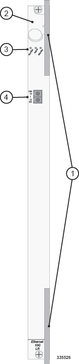
| Item | Description |
|---|---|
| 1 | Card Ejector Levers—Use to insert/remove card to/from chassis. |
| 2 | Interlock Switch—In its Down position the interlock switch notifies system to safely power down the card prior to its removal. |
| 3 | Card Level Status LEDs—Show the status of the card. See Applying Power and Verifying Installation for definitions. |
| 4 | Gigabit Ethernet Interface(s)—10 Gigabit Ethernet (GE) SFP+ modules. 10Base-SR and 10Base-LR interfaces are supported, depending on the SFP+ module installed. |
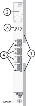
Optical Line Card (OLC2)
The OLC2 is labeled OLC2 OC-3/STM-1 Multi Mode (or Single Mode depending on SFP type). The OLC2 supports either OC-3 or STM-1 signaling and ATM.
The OLC2 support both SDH and SONET. The basic unit of framing in SDH is STM-1 (Synchronous Transport Module level - 1), which operates at 155.52 Mbps. SONET refers to this basic unit as STS-3c (Synchronous Transport Signal - 3, concatenated), but its high-level functionality, frame size, and bit-rate are the same as STM-1.
SONET offers an additional basic unit of transmission, STS-1 (Synchronous Transport Signal - 1), operating at 51.84 Mbps—exactly one third of an STM-1/STS-3c. The OLC2 concatenates three STS-1 (OC-1) frames to provide transmission speeds up to 155.52 Mbps with payload rates of 149.76 Mbps and overhead rates of 5.76 Mbps.
The OLC2 optical fiber line card supports network connectivity through Iu or IuPS interfaces to the UMTS Terrestrial Radio Access Network (UTRAN). These interfaces are commonly used with our SGSN products to provide either non-IP 3G traffic or all IP 3G traffic (for all-IP packet-based networking) over ATM (Asynchronous Transfer Mode).
| Module Type | Card Identification | Interface Type | Cable Specifications |
|---|---|---|---|
| Single-mode Optical Fiber | ATM/POS OC-3 SM IR-1 | Single-mode Fiber, LC duplex female connector |
Fiber Types: Single-mode optical fiber Wavelength: 1310 nm Core Size: 9 micrometers Cladding Diameter: 125 micrometers Range: Intermediate/21 kilometers Attenuation: 0.25 dB/KM Min/Max Tx Power: -15 dBm/-8 dBm Rx Sensitivity: -28 dBm |
| Multi-mode Optical Fiber | ATM/POS OC-3 Multi-Mode | Multi-mode Fiber, LC duplex female connector |
Fiber Types: Multi-mode optical fiber Wavelength: 1310 nm Core Size: 62.5 micrometers Cladding Diameter: 125 micrometers Range: Short/2 kilometers Min/Max Tx Power: -19 dBm/-14 dBm Rx Sensitivity: -30 dBm |
The OLC2 supports the Star Channel (1 Gbps) for faster FPGA upgrades and is Restriction of Hazardous Substances (RoHS) 6/6 compliant.
Install the OLC2 directly behind its respective (active) packet processing card. As with other line cards, install the Optical (ATM) Line Card in slots 17 through 23, 26 through 39, and 42 through 48.The following figures show the panel of the OLC2, indicating its ports and major components.
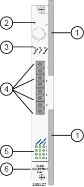
| Item | Description |
|---|---|
| 1 | Card Ejector Levers—Use to insert/remove card to/from chassis. |
| 2 | Interlock Switch—In its Down position, the interlock switch notifies the system to safely power down the card prior to its removal. |
| 3 | Card Level Status LEDs—Show the status of the card. |
| 4 |
Port connectors—Fiber LC duplex female connector. |
| 5 | Port Level Status LEDs—Show the status of a port. |
| 6 | Line Card
Label—Identifies the type of SFP modules and cabling supported:
|
Channelized Line Card (CLC2)
The CLC2 is also referred to as the Frame Relay line card. It provides frame relay over SONET or SDH. The CLC2 supports network connectivity through a gigabit interface to connect to the Packet Control Unit (PCU) of the base station subsystem (BSS) in a mobile network. These interfaces are commonly used with the SGSN product to support frame relay.
In North America, the card supplies ANSI SONET STS-3 (optical OC-3) signaling. In Europe, the card supplies SDH STM-1 (optical OC-3). The transmission rate for the card is 155.52 Mbps with 336 SONET channels for T1 and 252 SDH channels for E1.
Each CLC2 provides four optical fiber physical interfaces (ports). The ports are populated by a Small Form-factor Pluggable (SFP) modules which include an LC-type connector. The ports of the CLC2 supports two types of SFP modules and cabling, as shown in the following table.
| Module Type | Card Identification | Interface Type | Cable Specifications |
|---|---|---|---|
| Single-mode Optical Fiber | Channelized (STM-1/OC-3) SM IR-1 | Single-mode Fiber, LC duplex female connector |
Fiber Types: Single-mode optical fiber Wavelength: 1310 nm Core Size: 9 micrometers Cladding Diameter: 125 micrometers Range: Intermediate/21 kilometers Attenuation: 0.25 dB/KM Min/Max Tx Power: -15 dBm/-8 dBm Rx Sensitivity: -28 dBm |
| Multi-mode Optical Fiber | Channelized (STM-1/OC-3) Multi-Mode | Multi-mode Fiber, LC duplex female connector |
Fiber Types: Multi-mode optical fiber Wavelength: 1310 nm Core Size: 62.5 micrometers Cladding Diameter: 125 micrometers Range: Short/2 kilometers Min/Max Tx Power: -19 dBm/-14 dBm Rx Sensitivity: -30 dBm |
The CLC2 supports the Star Channel (1 Gbps) for faster FPGA upgrades and is Restriction of Hazardous Substances (RoHS) 6/6 compliant.
Install the CLC2 directly behind its respective (Active) packet processing card. You may optionally install CLC2s behind a redundant (Standby) packet processing card. As with other line cards, install the Channelized Line Cards in slots 17 through 23, 26 through 39, and 42 through 48.
The following figures show the panel of the CLC2 Channelized Line Cards, identifying their interfaces and major components.
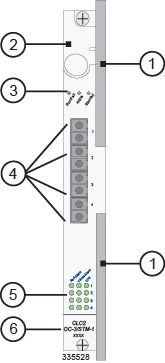
| Item | Description |
|---|---|
| 1 | Card Ejector Levers—Use to insert/remove card to/from chassis. |
| 2 | Interlock Switch—In its Down position the interlock switch notifies the system to safely power down the card prior to its removal. |
| 3 | Card Level Status LEDs—Show the status of the card. |
| 4 |
Port connectors—Fiber LC duplex female connector. |
| 5 | Port Level Status LEDs—Show the status of a port. |
| 6 | Line Card
Label—Identifies the type of SFP modules and cabling supported:
|
-
ITU-T - Recommendation G.704 - Synchronous Frame Structures Used at 1544, 6312, 2048, 8448 and 44736 kbps Hierarchical Levels, October, 1998.
-
ITU-T - Recommendation G.706 - Frame Alignment and Cyclic Redundancy Check (CRC) Procedures Relating to Basic Frame Structures Defined in Recommendation G.704, April 1991.
-
ITU-T - Recommendation G.707 Network Node Interface for the Synchronous Digital Hierarchy (SDH), December 2003.
-
ITU-T - Recommendation G.747 Second Order Digital Multiplex Equipment Operating at 6312 kbps and Multiplexing Three Tributaries at 2048 kbps, 1993.
-
ITU-T - Recommendation G.751 Digital Multiplex Equipment Operating at the Third Order Bit Rate of 34 368 kbps and the Fourth Order Bit Rate of 139 264 kbps and Using Positive Justification, 1993.
-
ITU-T - Recommendation G.775, - Loss of Signal (LOS) and Alarm Indication Signal (AIS) Defect Detection and Clearance Criteria, November 1994.
-
ITU-T - Recommendation G.783 Characteristics of Synchronous Digital Hierarchy (SDH) Equipment Functional Blocks, February 2004.
-
ITU-T - Recommendation G.823, -The Control of Jitter and Wander within Digital Networks which are based on the 2048 kbps Hierarchy, March 2000.
-
ITU-T - Recommendation G.824 The Control of Jitter and Wander within Digital Networks which are based on the 1544 kbps Hierarchy, March 2000.
-
ITU-T - Recommendation G.825 Control of Jitter and Wander within Digital Networks Which are Based on the Synchronous Digital Hierarchy (SDH) Series G: Transmission Systems and Media, Digital Systems and Networks Digital Networks - Quality and Availability Targets, March 2000.
-
ITU-T - Recommendation G.832 Transport of SDH elements on PDH networks Frame and multiplexing structures, October 1998.
-
ITU-T - Recommendation G.957 Optical interfaces for equipment and systems relating to the Synchronous Digital Hierarch, March 2006.
-
ITU-T - Recommendation I.431 - Primary Rate User-Network Interface Layer 1 Specification, March 1993.
-
ITU-T - Recommendation O.150 - General Requirements for Instrumentation Performance Measurements on Digital Transmission Equipment, May 1996.
-
ITU-T - Recommendation O.151 - Error Performance Measuring Equipment Operating at the Primary Rate and Above, October 1992.
-
ITU-T - Recommendation O.152 - Error Performance Measuring Equipment for Bit Rates of 64 kbps and N x 64 kbps, October 1992.
-
ITU-T - Recommendation O.153 - Basic Parameters for the Measurement of Error Performance at Bit Rates below the Primary Rate, October 1992.
-
ITU-T - Recommendation Q.921 - ISDN User-Network Interface - Data Link Layer Specification, September 1997.
-
ITU-T - Recommendation Q.922 - ISDN data link layer specification for frame mode bearer services.
-
ITU-T - Recommendation Q.933 Annex E.
-
Frame Relay Forum - FRF 1.2 - User-to-Network Interface (UNI).
-
Frame Relay Forum - FRF 2.1 - Frame Relay Network-to-Network Interface (NNI).
-
Frame Relay Forum - FRF 5.0 - Network Interworking.
-
Frame Relay Forum - FRF 8.1 - Service Interworking.
-
Frame Relay Forum - FRF 12.0 - Frame Relay Fragmentation.
Card Interlock Switch
Each card has a switch interlock mechanism that is integrated with the upper card ejector lever. The interlock ensures proper notification to the system before a card is removed. You cannot configure or place a card into service until you slide the card interlock switch upward. This locks the upper ejector lever in place and signals the system that the card is ready for use.
Sliding the interlock downward to the unlocked position allows you to operate the upper ejector lever. This sliding lock mechanism notifies the system to migrate various processes on the card prior to its removal.
The following figure shows how the card interlock switch works in conjunction with the ejector lever.
Card Identifiers
The table below cross-references ASR 5000 application and line cards by acronym, label, variant, and Cisco part identifier (PID).
| Descriptor | Acronym | Label | Variant |
|---|---|---|---|
| Application Cards | |||
| System Management Card | SMC | System Management | None |
| Packet Services Card 16GB | PSCA | End of Life (not supported in Release 16.0+) | |
| Packet Services Card 32GB | PSC2 | Packet Services 2 32GB | None |
| Packet Services Card 64GB | PSC3 | Packet Services 3 64GB | None |
| Packet Processing Card 16GB | PPC | End of Life (not supported in Release 16.0+) | |
| Switch Processor Input/Output | SPIO | Switch Processor I/O | SPIO, E1 BNC BITS |
| SPIO, T1 3-Pin BITS | |||
| SPIO, E1 BNC BITS with Stratum 3 module | |||
| SPIO, T1 3-Pin BITS with Stratum 3 module | |||
| Line Cards | |||
| Redundancy Crossbar | RCC | Redundancy Crossbar | None |
| FELC Ethernet 10/100 Line Card | End of life (replaced by FLC2) | ||
| FELC Ethernet 10/100 Line Card 2 | FLC2 | Ethernet 10/100 | None |
| GELC Ethernet 1000 Line Card | End of life (replaced by GLC2) | ||
| GLC2 Ethernet 1000 Line Card | GLC2 | Ethernet 1000 SX | with SX MM Short Haul SFP |
| Ethernet 1000 LX | with LX SM SFP | ||
| Ethernet 1000 T | with copper SFP | ||
| QGLC 4-Port Ethernet 1000 Line Card | QGLC | Ethernet 1000 SX | with SX MM Short Haul SFP |
| Ethernet 1000 LX | with LX SM SFP | ||
| Ethernet 1000 T | with copper SFP | ||
| QGLC Rev2 4-Port Ethernet 1000 Line Card | QGLC | Ethernet 1000 SX | with SX MM Short Haul SFP |
| Ethernet 1000 LX | with LX SM SFP | ||
| Ethernet 1000 T | with copper SFP | ||
| XGLC 1-Port 10 Gigabit Ethernet Line Card | XGLC | Ethernet 10G SR | with MM SFP+ |
| Ethernet 10G LR | with SM SFP+ | ||
| Channelized 4-port Line Card | CLC2 | CLC2 OC-3/STM-1 | with MM SFP |
| with SM SFP | |||
| Optical 4-port (ATM) Line Card | OLC2 | OLC2 OC-3/STM-1 | with MM SFP |
| with SM SFP | |||
 Feedback