- About this Guide
- ASR 5000 Hardware Platform Overview
- Installation Procedure Overview
- Chassis Installation
- Application Card Installation
- Line Card Installation
- Cabling the Switch Processor Input/Output Line Card
- Cabling the Fast Ethernet (10/100) Line Card
- Cabling the Gigabit Ethernet Line Cards
- Cabling the Optical (ATM) Line Cards
- Cabling the Channelized Line Cards
- Cabling the Power Filter Units
- Applying Power and Verifying the Installation
- System Monitoring
- Adding Application and Line Cards to an Existing Installation
- Removing and Installing SMC PC Cards
- Replacing the Chassis Air Filter
- Replacing a Power Filter Unit
- Replacing Upper or Lower Fan Tray
- Replacing Application Cards
- Replacing Line Cards
- Technical Specifications
- Safety, Electrical and EMC Certifications
- Environmental Specifications
- Hardware Product Support Matrix
- Preparing a Full-Height Line Card Slot
- RMA Shipping Procedures
- Spare Component Recommendations
Cabling the Channelized Line Cards
This chapter provides information about the physical interfaces and instructions for installing the cables on the CLC2 (STM-1/OC-3).
This chapter includes the following sections:
Channelized Line Card Interfaces
The CLC2 card supports two types of Small Form-factor Pluggable (SFP) transceiver modules. The type of optical fiber interface on the line card is dictated by the SFP modules installed on the card. The SFP modules are hot-pluggable.
| Module Type | Card Identification | Interface Type | Cable Specifications |
|---|---|---|---|
|
Single-mode Optical Fiber |
Channelized (STM-1/OC-3) SM IR-1 |
Single-mode Fiber, LC duplex female connector |
Fiber Types: Single-mode optical fiber Wavelength: 1310 nm Core Size: 9 micrometers Cladding Diameter: 125 micrometers Range: Intermediate/21 kilometers Attenuation: 0.25 dB/KM Min/Max Tx Power: -15 dBm/-8 dBm Rx Sensitivity: -28 dBm |
|
Multi-mode Optical Fiber |
Channelized (STM-1/OC-3) Multi-Mode |
Multi-mode Fiber, LC duplex female connector |
Fiber Types: Multi-mode optical fiber Wavelength: 1310 nm Core Size: 62.5 micrometers Cladding Diameter: 125 micrometers Range: Short/2 kilometers Min/Max Tx Power: -19 dBm/-14 dBm Rx Sensitivity: -30 dBm |
The SFP interface is only certified to work with SFP transceiver modules purchased from Cisco for use with the CLC2.
Because of the optical SFP interface, this product has been tested and found to comply with the limits for Class 1 laser devices for IEC825, EN60825, and 21CFR1040 specifications.
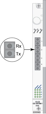
The following figure shows the LC-connectors for the CLC2. Each SFP fiber interface provides both transmit (TX) and receive (RX) on the port.
Cabling the Optical SFP Interface
To use the optical SFP interface on the a channelized line card, follow the instructions below.
Be sure to label the interface cables with their destination prior to connecting them to the CLC2. This will assure proper reconnection should the card need to be serviced.
 Note | Only trained and qualified personnel should install, replace, or service this equipment. Invisible laser radiation may be emitted from the aperture of the port when no cable is connected. Avoid exposure to laser radiation and do not look into open apertures. Be sure to keep the cover on the interface when it is not in use. Laser Klasse 1 - nur speziell ausgebildetes Personal darf dieses Geraet warten. Nicht in den Laser schauen, um Augenverletzungen zu vermeiden. Nicht genutzte Buchsen mit der entsprechenden Kappe verschliessen. |
 Feedback