- About this Guide
- ASR 5000 Hardware Platform Overview
- Installation Procedure Overview
- Chassis Installation
- Application Card Installation
- Line Card Installation
- Cabling the Switch Processor Input/Output Line Card
- Cabling the Fast Ethernet (10/100) Line Card
- Cabling the Gigabit Ethernet Line Cards
- Cabling the Optical (ATM) Line Cards
- Cabling the Channelized Line Cards
- Cabling the Power Filter Units
- Applying Power and Verifying the Installation
- System Monitoring
- Adding Application and Line Cards to an Existing Installation
- Removing and Installing SMC PC Cards
- Replacing the Chassis Air Filter
- Replacing a Power Filter Unit
- Replacing Upper or Lower Fan Tray
- Replacing Application Cards
- Replacing Line Cards
- Technical Specifications
- Safety, Electrical and EMC Certifications
- Environmental Specifications
- Hardware Product Support Matrix
- Preparing a Full-Height Line Card Slot
- RMA Shipping Procedures
- Spare Component Recommendations
Cabling the Switch Processor Input/Output Line Card
This chapter provides information on the Switch Processor Input/Output (SPIO) line card interfaces and instructions for installing the cables.
Class 1 Laser Compliance Notice Because of the SFP interfaces, this product has been tested and found to comply with the limits for Class 1 laser devices for IEC825, EN60825, and 21CFR1040 specifications.
This chapter includes the following sections:
- SPIO Interfaces
- Connecting to the Management LAN
- Connecting to the Serial Console Port
- Connecting to a BITS Timing Source
- Connecting to the CO Alarm Interface
SPIO Interfaces
The SPIO is available with the following types of interfaces:
Two Gigabit Ethernet, fiber optical (SFP)
Two 1000Base-T Ethernet, copper (RJ-45)
One RS-232 interface (RJ-45)
One Central Office alarms (10-pin Molex))
One BITS (BNC or 3-pin connector)
E1 BNC BITS Interface Version
The figure and table that follow provide information on the various interfaces in this version of the SPIO.
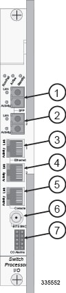
| Item | Label | Connector Type | Description |
|---|---|---|---|
|
1 |
SFP 1 |
Optical fiber, Small Form-factor Pluggable |
Gigabit Ethernet interface for connecting to management LAN |
|
2 |
SFP 2 |
Optical fiber, Small Form-factor Pluggable |
Gigabit Ethernet interface for connecting to management LAN |
|
3 |
Ethernet 1 |
RJ-45 |
10/100/1000 Ethernet interface for connecting to management LAN |
|
4 |
Ethernet 2 |
RJ-45 |
10/100/1000 Ethernet for connecting to management LAN |
|
5 |
Console |
RJ-45 |
RS-232 interface for local administration of the system |
|
6 |
BITS BNC |
75W BNC |
Building Integrated Timing Supply (BITS) interface for analog E1 clock source [software selectable] NOTE: This interface is not used for systems supporting data applications. |
|
7 |
CO Alarms |
10-pin Molex |
Isolated dry-contact relay interfaces for connection to Central Office (CO) alarm monitoring panel |
T1 3-Pin BITS Interface Version
The figure and table that follow provide information on the various interfaces in this version of the SPIO.
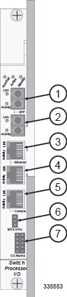
| Item | Label | Connector Type | Description |
|---|---|---|---|
|
1 |
SFP 1 |
Optical fiber, Small Form-factor Pluggable |
Gigabit Ethernet interface for connecting to management LAN |
|
2 |
SFP 2 |
Optical fiber, Small Form-factor Pluggable |
Gigabit Ethernet interface for connecting to management LAN |
|
3 |
Ethernet 1 |
RJ-45 |
10/100/1000 Ethernet for connecting to management LAN |
|
4 |
Ethernet 2 |
RJ-45 |
10/100/1000 Ethernet for connecting to management LAN |
|
5 |
Console |
RJ-45 |
RS-232 interface for local administration of the system |
|
6 |
BITS 3-Pin |
3-pin Wire Wrap |
BITS interface for T1 (DS1) clock source [software selectable] NOTE: This interface is not used for systems supporting data applications. |
|
7 |
CO Alarms |
10-pin Molex ® |
Isolated dry-contact relay interfaces for connection to Central Office (CO) alarm monitoring panel |
Connecting to the Management LAN
The SPIO provides two types of interfaces for physical connection to the management LAN: the fiber optic SFP and the Ethernet (RJ-45) interfaces.
Be sure to label the interface cables with their destination prior to connecting them to the SPIO. This will assure proper reconnection should the card need to be serviced.
Using the SFP Interfaces
The two optical 1000Base-SX SFP interfaces are hot-pluggable 802.3z-compliant Gigabit Ethernet interfaces that take their configuration from the inserted cable type. Refer to the following table for information about supported cable specifications.
| Module Type | Connector Type | Cable Specifications |
|---|---|---|
|
1000Base-SX |
Fiber, LC duplex female connector |
Fiber Type: Multi-mode fiber (MMF), 850 nm wavelength Minimum Tx Power: -9.5 dBm Rx Sensitivity: -17 dBm |
The SFP interface is only certified to work with SFP transceiver modules purchased from Cisco for use with the SPIO card.
Be sure to label the interface cables with their destination prior to connecting them to the SPIO card. This will assure proper reconnection should the card need to be serviced.
 Note | Class 1 Laser Device Only trained and qualified personnel should be allowed to install, replace, or service this equipment. Invisible laser radiation may be emitted from the aperture of the port when no cable is connected. Avoid exposure to laser radiation and do not look into open apertures. Be sure to keep the cover on the interface when it is not in use. Laser Klasse 1 - nur speziell ausgebildetes Personal darf dieses Geraet warten. Nicht in den Laser schauen, um Augenverletzungen zu vermeiden. Nicht genutzte Buchsen mit der entsprechenden Kappe verschliessen. |
Each optical SFP interface is equipped with a transmit (TX) port and a receive (RX) port as shown in the following figure.
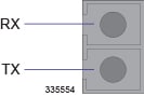
Additionally, the SPIO provides two light emitting diode (LED) status indicators for this interface:
Connect to the SFP interfaces by following the instructions below.
Using the Ethernet RJ-45 Interfaces
The two RJ-45 interfaces are auto-sensing 10/100/1000Base-TX Ethernet interfaces. Refer to the figure and table that follow for pinouts for the RJ-45 Ethernet ports.
To comply with GR-1089 intra-building, lightning-immunity requirements and ensure compliance with Radiated Emissions Criteria, you must use shielded-twisted pair (STP) copper cable and ensure that it is properly terminated at both ends.
The 1000Base-TX (RJ-45) management ports of the SPIO are suitable for connection to intra-building or unexposed wiring or cabling only. These intra-building ports MUST NOT be metallically connected to interfaces that connect to the outside plant (OSP) or its wiring. These interfaces are designed for use as intra-building interfaces only (Type 2 or Type 4 ports as described in GR-1089-CORE, Issue 5) and require isolation from the exposed OSP cabling. The addition of Primary Protectors is not sufficient protection in order to connect these interfaces metallically to OSP wiring.
Be sure to label the interface cables with their destination prior to connecting them to the SPIO card. This will assure proper reconnection should the card need to be serviced.
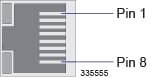
| Pin | 100Base-TX 100Mbps Cat5 | 1000Base-TX 1Gbps Cat5+ |
|---|---|---|
|
1 |
TX+ |
BI DA+ |
|
2 |
TX- |
BI DA- |
|
3 |
RX+ |
BI DB+ |
|
4 |
No used |
BI DC+ |
|
5 |
No used |
BI DC- |
|
6 |
RX- |
BI DB- |
|
7 |
No used |
BI DD+ |
|
8 |
No used |
BI DD- |
|
RX = Receive Data TX = Transmit Data BI = BI directional data DA, DB, DC, DD = Data Pair A, B, C, and D |
||
To use the RJ-45 interfaces, simply plug the Ethernet cable into either the Ethernet 1 or Ethernet 2 interface.
Connecting to the Serial Console Port
The Console port is an RJ-45 RS-232 interface that provides access to the system's command line interface (CLI). This serial interface communicates at 9600 to 115200 bps (default = 115200 bps).
The RJ-45 pinout of tis interface is described in the figure and table that follow.
To ensure compliance with Radiated Emissions Criteria, you must use shielded-twisted pair (STP) copper cable and ensure that it is properly terminated at both ends.
| RJ-45 Pin | Signal Description | Signal Type |
|---|---|---|
|
1 |
Clear to Send (CTS) |
Input |
|
2 |
Data set Ready (DSR) |
Input |
|
3 |
Receive Data (RX) |
Input |
|
4 |
Signal Ground (SGND) |
N/A |
|
5 |
Ready to Send (RTS) |
Output |
|
6 |
Transmit Data (TX) |
Output |
|
7 |
Data Carrier Detect (DCD) |
Input |
|
8 |
Data Terminal Ready (DTR) |
Output |
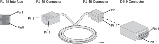
DB-9 to RJ-45 Adapter
SPIOs are shipped with an RJ-45-to-RJ-45 serial cable and an RJ-45-to-DB-9 adapter. The DB-9S conductor on the adapter is female. If you use the cable and adaptor together, refer to the following figure and table.
If the console cable is to be used in a null-modem configuration, the workstation or terminal server must provide a carrier-detect signal.
| SPIO Console Port Interface | Console Cable | RJ-45-to-DB-9 Adapter | |||
|---|---|---|---|---|---|
| Signal | Signal Type | RJ-45 Pin | RJ-45 Pin | DB-9S Pin | Signal |
|
Clear to Send (CTS) |
Input |
1 |
1 |
7 |
RTS |
|
Data Set Ready (DSR) |
Input |
2 |
2 |
4 |
DTR |
|
Receive Data (RxD) |
Input |
3 |
3 |
3 |
TxD |
|
Signal Ground (SGND) |
N/A |
4 |
4 |
5 |
SGND |
|
Ready To Send (RTS) |
Output |
5 |
5 |
8 |
CTS |
|
Transmit Data (TxD) |
Output |
6 |
6 |
2 |
RxD |
|
Data Carrier Detect (DCD) |
Input |
7 |
7 |
1 |
DCD |
|
Data Terminal Ready (DTR) |
Output |
8 |
8 |
6 |
DSR |
USB to DB-9 Adapter
A USB to Serial DB-9 adapter is supplied with each system. The DB-9 connector on the adapter is male and can be used in conjunction with the Console RJ-45 Cable and DB-9 Adapter to connect a laptop or workstation to the R-J45 port on the SPIO.
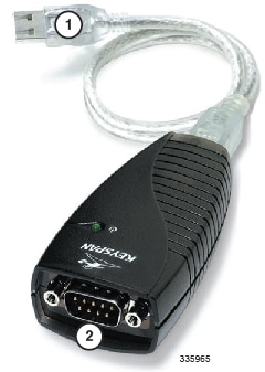
| 1 | USB 1.1 Type B connector | 2 | DB-9 connector (male) |
| DB-9 Pin | Signal Description | Signal type | Console Port |
|---|---|---|---|
| 1 | Data Carrier Detect (DCD) | Input | Unused |
| 2 | Receive Data (RxD) | Input | TxD |
| 3 | Transmit Data (TxD) | Output | RxD |
| 4 | Data Terminal Ready (DTR) | Output | Unused |
| 5 | Signal Ground (SGND) | Ground | Ground |
| 6 | Data Set Ready (DSR) | Input | Unused |
| 7 | Request To Send (RTS) | Output | Unused |
| 8 | Clear To Send (CTS) | Input | Unused |
| 9 | Ring Indicator (RI) | Input | Unused |
This adapter provides a serial port on a laptop or workstation that does not have one. It draws power from the USB port.
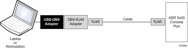
Connecting to the Console Port
The following instructions assume that you are using the RJ-45-to-RJ-45 cable with the RJ-45-to-DB-9 serial (EIA-232) adapter shipped with the SPIO to connect to the Console port. Use these components to connect to a workstation running a communications application that can access the workstation's serial port, such as Minicom for Linux® or HyperTerminal® for Windows.
Connecting to a BITS Timing Source
The SPIO can be optionally equipped with a BITS interface that derives a 1544 kHz (SONET T1 framing) or 2048 kHz (SDH E1 framing) clock signal from an external Building Integrated Timing Supply to synchronize line card timing. The BITS source derives its timing from a primary reference source (PRS), such as a Stratum 1 clock or Global Positioning System (GPS) signal.
Connection to the BITS is via a BNC coaxial cable (E1) or 3-pin wire-wrap connector (T1).
External BITS timing is an alternative to using clock signals derived from an ATM port on an OLC2, or an ANSI SONET STS-3/SDH STM-1 port on a CLC2. (Line-derived clocking requires that the SPIO be equipped with the optional Stratum 3 clock module.) For additional information, refer to the ATM Port Configuration Mode Commands and Channelized Port Configuration Mode Commands chapters of the Command Line Interface Reference.
Always refer to the interface and signaling specifications in the OEM documentation supplied with the BITS source. Your NOC may also have detailed specifications for distributing the BITS clock signals to network devices such as the ASR 5000.
BITS E1 BNC Interface
The BNC version of the SPIO employs a 75-ohm coaxial BNC connector that accepts an analog E1 BITS signal. The following figure shows the BITS BNC timing interface.
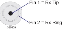
Use 75-ohm coaxial cable (RG-59/U) between the BITS and the SPIO BNC interface to carry the E1 signal.At the SPIO, terminate the cable with a 75-ohm BNC male connector.
BITS T1 3-Pin Interface
The 3-pin version of the SPIO employs a wire-wrap connector that accepts a T1 (DS1) BITS data signal (all ones). The following figure shows the BITS timing interface wire-wrap pin-out.
Use 22 AWG, twisted-pair, 100-ohm shielded cable between the BITS and SPIO wire-wrap interface to carry the DS1 signal.
BITS Timing Configuration
For additional information on BITS configuration, refer to the BITS Port Configuration Mode Commands chapter of the Command Line Interface Reference.
Connecting to the CO Alarm Interface
The Central Office (CO) Alarm interface utilizes a 10-pin Molex female-connector fro interconnection with the three normally closed dry-contact relays. These relays trigger external audio and/or visual indicators for the following three alarm levels:
-
Minor Alarm: This alarm is triggered when a high temperature is detected on a card, causing the fan tray to switch its fans to high speed.
-
Major Alarm: This alarm is triggered by a: -
Critical Alarm: This alarm is triggered when a severe degradation in service is detected. For example, if the system is supporting a large number of subscribers and packet processing cards are removed thus significantly reducing the amount of available CPU and memory resources.
The CO alarm interface pinout is provided in the following figure and table.
| Pin | Signal |
|---|---|
|
1 |
Major Alarm - Normally closed |
|
2 |
Major Alarm - Common |
|
3 |
Major Alarm - Normally open |
|
4 |
Minor Alarm - Normally closed |
|
5 |
Minor Alarm - Common |
|
6 |
Minor Alarm - Normally open |
|
7 |
Signal |
|
8 |
Major Alarm - Normally closed |
|
9 |
Major Alarm - Common |
|
10 |
Major Alarm - Normally open |
The 8-foot (2.4 meter) CO alarm cable shipped with the chassis supports redundant SPIO card installations. This "Y" cable has two Molex connectors on one end that are keyed to fit into the CO Alarm interfaces in one direction only. Each connector mates with one of the side-by-side SPIO cards. On the opposite end is a 9-pin terminal block that you can mount to the telco cabinet or equipment rack frame.
The following figure and table display this cable assembly and its pinouts.
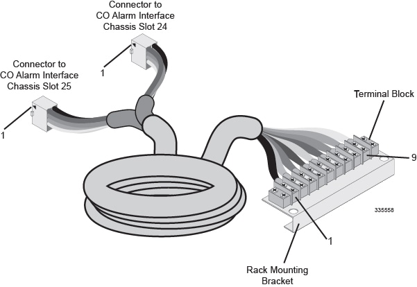
| SPIO CO Alarms IF Pin Number | Cable Wire Color | Terminal Block Position No. | Signal |
|---|---|---|---|
|
1 |
Black |
1 |
Major Alarm - Normally closed |
|
2 |
Orange |
2 |
Major Alarm - Common |
|
3 |
Red |
3 |
Major Alarm - Normally open |
|
4 |
Brown |
4 |
Minor Alarm - Normally closed |
|
5 |
Yellow |
5 |
Minor Alarm - Common |
|
6 |
Green |
6 |
Minor Alarm - Normally open |
|
7 |
Blue |
7 |
Critical Alarm - Normally closed |
|
8 |
Violet |
8 |
Critical Alarm - Common |
|
9 |
Gray |
9 |
Critical Alarm - Normally open |
|
10 |
Not wired |
Not equipped |
Unused |
Electrical Characteristics
Each of the three dry-contact relay switches is rated to support a maximum switching current of 1A@30VDC. The relay contacts should not directly connected to high current devices such as sirens and flashing lamps.
The CO alarm interface of the SPIO is suitable for connection to intra-building or unexposed wiring or cabling only. This interface MUST NOT be metallically connected to interfaces that connect to the outside plant (OSP) or its wiring. This interface is designed for use as an intra-building interface only (Type 2 or Type 4 ports as described in GR-1089-CORE, Issue 5) and requires isolation from the exposed OSP cabling. The addition of Primary Protectors is not sufficient protection in order to connect these interfaces metallically to OSP wiring.
Central Office Alarm Wiring Example
The following figure depicts how the dry-contact relays can each control up to two external alarm indicators. In this example, the CO alarm interface is connected to a CO Alarm Panel, where green LEDs are wired to indicate normal operation, and red LEDs are wired to indicate an alarm condition.
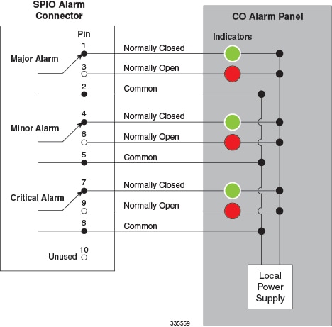
With all relays de-energized (normally closed), the green LED is illuminated. If an alarm relay is energized, the NO (normally open) contact closes and the red LED is illuminated.
 Feedback