- About this Guide
- ASR 5000 Hardware Platform Overview
- Installation Procedure Overview
- Chassis Installation
- Application Card Installation
- Line Card Installation
- Cabling the Switch Processor Input/Output Line Card
- Cabling the Fast Ethernet (10/100) Line Card
- Cabling the Gigabit Ethernet Line Cards
- Cabling the Optical (ATM) Line Cards
- Cabling the Channelized Line Cards
- Cabling the Power Filter Units
- Applying Power and Verifying the Installation
- System Monitoring
- Adding Application and Line Cards to an Existing Installation
- Removing and Installing SMC PC Cards
- Replacing the Chassis Air Filter
- Replacing a Power Filter Unit
- Replacing Upper or Lower Fan Tray
- Replacing Application Cards
- Replacing Line Cards
- Technical Specifications
- Safety, Electrical and EMC Certifications
- Environmental Specifications
- Hardware Product Support Matrix
- Preparing a Full-Height Line Card Slot
- RMA Shipping Procedures
- Spare Component Recommendations
Application Card Installation
This chapter provides information on chassis configurations and instructions for installing application cards. Line cards are discussed in the Line Card Installation chapter.
This chapter includes the following sections:
Chassis Slot Numbering and Assignments
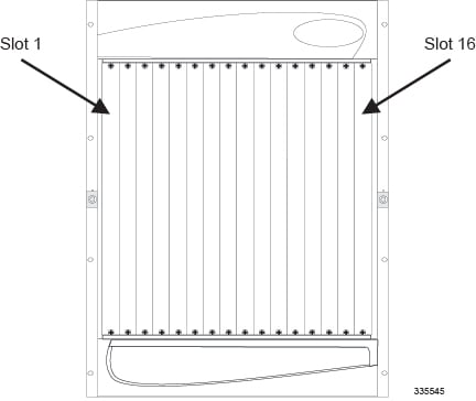
The chassis has 16 front-loading slots that host application cards. This allows the installation of redundant components and provides ample room for expanding the system. Chassis slots are labeled 1 through 16 from left to right.
ASR 5000 Platform
The following application cards are supported for use in the ASR 5000 chassis:
- System Management Card (SMC): The
Session Management Card (SMC) is used with the
packet processing cards (PSC2 or PSC3) in the ASR 5000
hardware platform. It serves as the primary controller, initializes
the entire system, and loads the software's configuration
image into other cards in the chassis. Up to two SMCs can
be installed in the chassis: one primary and one redundant "hot-standby" card. Chassis
slots 8 and 9 are reserved for the SMC only. By default, when
the chassis' power is on, the SMC in slot 8 is active. The
other SMC is automatically placed into standby mode.

CautionDo not place any card other than an SMC into slots 8 or 9 of the ASR 5000. Doing so will cause damage to the card and possibly the chassis' mid-plane.
Packet Processing Cards: The packet services cards provide the packet processing and forwarding capabilities within a system. Each packet processing card type supports multiple contexts, which allows you to overlap or assign duplicate IP address ranges in different contexts. The minimum recommended redundancy for packet services cards is one redundant card for up to 13 active cars.
| Application Card Type | Chassis Slot Number(s) | Description |
|---|---|---|
System Management Card (SMC) |
8 |
Primary SMC |
9 |
Redundant SMC |
|
Packet Processing Cards |
1 through 7 and 10 through 16 |
Active or redundant packet processing cards all of the same type |
To achieve optimal airflow performance in minimum system deployments, populate packet services cards within the chassis from the middle of the chassis outward. Leave an empty slot between the cards, when possible. For example, for four PSC2s, use slots 3, 5, 12, and 14. For two PSC2s, use slots 5 and 12. For more detailed information on SMCs and packet processing card types, refer to the Hardware Platform Overview chapter.
Packet Processing Card Redundancy
To optimize network efficiency and minimize down time, the system supports 1:n redundancy for packet processing cards of the same type.
When the system boots up, all packet processing cards enter standby mode, which means that the cards are available for use but offline. Installed components are made active through the software configuration process. Cards that are not configured to enter active mode, which brings them online, remain in standby mode as redundant components. Packet processing cards that normally operate in standby mode do not require line cards to be installed directly behind them, as these line cards are not used.
For additional information about RCCs, refer to Line Card Installation in this guide.
Recommended Minimum Chassis Configuration
The recommended minimum chassis configuration for application cards, including redundancy, is as follows:
| Slot Number | Card | Card State |
|---|---|---|
|
8 |
SMC |
Active |
|
9 |
SMC |
Standby |
|
2 and 4 (see Note 1) 2, 3 and 4 (see Note 2) |
PSC2 or PSC3 |
Active |
|
11 (see Notes 1 and 2) |
PSC2 or PSC3 |
Standby |
Notes:
1. Minimum requirement for hardware redundancy.
2. Minimum requirement for hardware + software redundancy, MME service, SGSN service, as well as combined services on a single platform.
Install additional cards in the remaining chassis slots as required.
If you use the session recovery feature, a minimum of three active packet processing cards and one standby (redundant) packet processing card are required.
Installing Application Cards
The installation procedure is identical for all application cards. This section provides the instructions for installing application cards in the chassis.
Caution | During installation, maintenance, and/or removal, wear grounding wrist and/or heel straps to avoid ESD damage to the components. Failure to do so could result in damage to electrical components and could potentially void your warranty. |
| Step 1 | Determine the type of application card you are installing. Each application card is identified by the text near the bottom of its front panel. | ||
| Step 2 | Determine which chassis slot to install the card in based on the information in Chassis Slot Numbering and Assignments.. | ||
| Step 3 | Remove the blanking panel, if one is installed, covering the slot. | ||
| Step 4 | Slide the interlock switch on the card fully downward and flip both ejector levers fully outward and away from the front panel. | ||
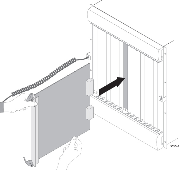
| Step 5 | Properly support
the weight of the card and align it with the upper and lower card guides of the
chassis slot. Gently slide the card into the slot until the levers touch the
chassis frame.
| ||
| Step 6 | Push the ejector levers inward firmly and straight until the card is seated in the chassis midplane and you cannot push the ejector levers in any further. Press firmly on the card's faceplate to ensure that it is fully seated. The card's front panel should be flush against the chassis' upper and lower card mounts for the slot. | ||
| Step 7 | Slide the
interlock switch on the front panel of the application card upward to lock the
ejector tab in place. The flange on the left-side of the interlock switch
prevents movement of the ejector tab when raised completely.
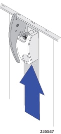
You must slide the interlock switch upward before securing the card's top screw to the mounting rail. | ||
| Step 8 | Use a Phillips #2 screwdriver to tighten the screws at the top and bottom of the application card's front panel to secure the card to the chassis. | ||
| Step 9 | Repeat step 1 through step 8 for every application card you are installing. | ||
| Step 10 | Install blanking
panels over any unused chassis slots.
| ||
| Step 11 | Proceed to the Line Card Installation chapter. |
 Feedback