- About this Guide
- ASR 5000 Hardware Platform Overview
- Installation Procedure Overview
- Chassis Installation
- Application Card Installation
- Line Card Installation
- Cabling the Switch Processor Input/Output Line Card
- Cabling the Fast Ethernet (10/100) Line Card
- Cabling the Gigabit Ethernet Line Cards
- Cabling the Optical (ATM) Line Cards
- Cabling the Channelized Line Cards
- Cabling the Power Filter Units
- Applying Power and Verifying the Installation
- System Monitoring
- Adding Application and Line Cards to an Existing Installation
- Removing and Installing SMC PC Cards
- Replacing the Chassis Air Filter
- Replacing a Power Filter Unit
- Replacing Upper or Lower Fan Tray
- Replacing Application Cards
- Replacing Line Cards
- Technical Specifications
- Safety, Electrical and EMC Certifications
- Environmental Specifications
- Hardware Product Support Matrix
- Preparing a Full-Height Line Card Slot
- RMA Shipping Procedures
- Spare Component Recommendations
Adding Application and Line Cards to an Existing Installation
This chapter provides instructions for installing additional application and line cards in an installed chassis that is processing calls (a production system).
All application and line cards are hot swappable. You can install or remove cards from the chassis without powering the chassis down. However, it is strongly recommended that you add system components during a maintenance window.
This chapter includes the following sections:
- Chassis Slot Numbering and Assignments
- Adding Application Cards
- Adding Half-Height Line Cards
- Adding a 10 Gigabit Ethernet Line Card
Chassis Slot Numbering and Assignments
The following figure shows the front and rear chassis slots.
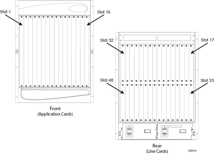
You must install the System Management Cards (SMCs) in slots 8 and 9. Their associated line cards are the Switch Processor Input Output card (SPIO) and the Redundant Crossbar Card (RCC). Assure that the SPIOs are installed in slots 24 and 25, and the RCCs are installed in slots 40 and 41 to prevent damage to the cards or the chassis midplane.
The 10 Gigabit Ethernet Line Card (XGLC) is a full-height line card that takes up the upper and lower slots in the back of the chassis. When referring to installed XGLCs, use the upper slot number only. Slot numbering for other installed half-height cards is maintained: 17 to 32 and 33 to 48, regardless of the number of installed XGLCs
Adding Application Cards
The installation procedure is identical for all application cards. This section provides the instructions for adding application cards to the chassis.
You can add single packet processing cards to a production system. However, you must reboot the system to ensure optimal operation and capacity. For this reason Cisco Systems suggests that you perform the installation during a maintenance window when a reboot will have minimal impact.
 Caution | During installation, maintenance, and/or removal, wear a grounding wrist strap to avoid ESD damage to the components. Failure to do so could result in damage to sensitive electronic components and potentially void your warranty. |
| Step 1 | Determine the type of application card you are installing. Each application card is identified by the label near the bottom of its front panel. | ||
| Step 2 | Determine which
chassis slot to install the card in based on the information in
Chassis Slot Numbering and Assignments..
To achieve optimal airflow performance in minimal system deployments, populate packet processing cards from the middle of the chassis outward, leaving an empty slot between them. For example, with four packet processing cards use slots 3, 5, 12, and 14. For two packet processing cards, place them in slots 5 and 12. | ||
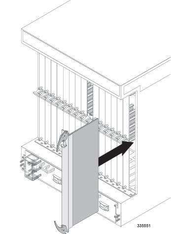
| Step 3 | Remove the
blanking panel, if one is installed, covering the slot.
| ||
| Step 4 | Slide the interlock switch on the card fully downward. Flip the ejector levers outward and away from the card's front panel. | ||
| Step 5 | Properly support
the weight of the card and align it with the upper and lower card guides of the
chassis slot. Gently slide the card into the slot until the levers touch the
chassis frame.
If you are installing PSCAs in a chassis that contains PSCs, refer to the Chassis Hybrid Mode Operation appendix for additional configuration information. 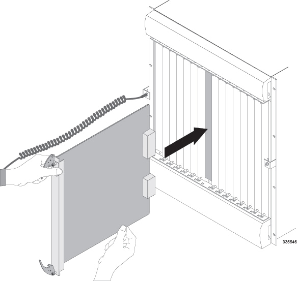
| ||
| Step 6 | Push the ejector levers inward firmly until the card is seated in the chassis midplane and you cannot push the ejector levers in any further. Press firmly on the card's faceplate to ensure that it is fully seated. The card's front panel should be flush against the chassis' upper and lower card mounts for the slot. | ||
| Step 7 | Slide the
interlock switch on the front panel of the application card upward to lock the
ejector tab in place. The flange on the left-side of the interlock switch
prevents movement of the ejector tab when raised completely.
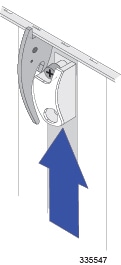
You must slide the interlock switch upward before securing the card's top screw to the mounting rail. | ||
| Step 8 | Use a Phillips #2 screwdriver to tighten the screws at the top and bottom of the application card's front panel to secure the card to the chassis. | ||
| Step 9 | Repeat step 1 through step 7 for every application card you are installing. | ||
| Step 10 | Install blanking
panels over any unused chassis slots.
| ||
| Step 11 | Proceed to the next sections of this chapter for instructions on adding the respective line card(s) for every application card just installed. |
Adding Half-Height Line Cards
This section provides instructions for adding half-height line cards to the chassis.
Caution | During installation, maintenance, and/or removal, wear a grounding wrist strap to avoid ESD damage to the components. Failure to do so could result in damage to sensitive electronic components and potentially void your warranty. |
| Step 1 | Determine the type of line card you are installing. Each line card is identified by the label near the bottom of its front panel. | ||||||||||||||
| Step 2 | Determine which chassis slot to install the card in based on the information in Chassis Slot Numbering and Assignments. | ||||||||||||||
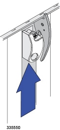
| Step 3 | Remove the
blanking panel covering the slot:
| ||||||||||||||
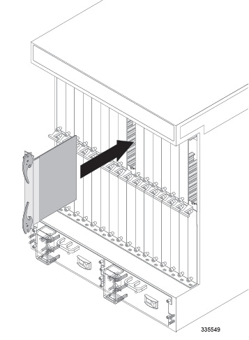
| Step 4 | Slide the interlock switch on the card fully downward. Flip the ejector levers outward and away from the card's front panel. | ||||||||||||||
| Step 5 | Hold the card by
its ejector levers and align the card with the upper and lower card guides of
the chassis slot. Gently slide it into the slot until the levers touch the
chassis frame.
| ||||||||||||||
| Step 6 | Push the ejector levers inward firmly until the card is firmly seated in the chassis midplane and the ejector levers can be pushed in no further. Press firmly on the card's faceplate to ensure that it is fully seated. The card's front panel should be flush against the chassis' upper and lower card mounts for the slot. | ||||||||||||||
| Step 7 | Slide the
interlock switch on the front panel of the line card upward to lock the ejector
tab in place. The flange on the left-side of the interlock switch prevents
movement of the ejector tab when raised completely.
| ||||||||||||||
| Step 8 | Use a Phillips #2 screwdriver to tighten the screws at the top and bottom of the line card's front panel to secure the card to the chassis. | ||||||||||||||
| Step 9 | Repeat step 1 through step 7 for every other line card that to be installed. | ||||||||||||||
| Step 10 | Install blanking
panels over any unused chassis slots.
| ||||||||||||||
| Step 11 | Refer to one of
the following chapters in this guide for information on cabling the line cards
you just installed.
|
Adding a 10 Gigabit Ethernet Line Card
The 10 Gigabit Ethernet Line Card (XGLC) is a full-height line card that occupies two half-height slots in the rear of the ASR 5000 chassis. It accepts a single Small Form-factor Pluggable+ (SFP+) transceiver module for network connectivity.
-
XGLC SR: Accepts a 10GBase-SR module for a fiber optical cable with a center wavelength of 850nm terminated by an LC connector. It can drive an optical signal up to 300 meters using 50/125um fiber (MMF), and up to 33 meters using 62.5/125um fiber (MMF).
-
XGLC LR: Accepts a 10GBase-LR module for a fiber optical cable with a center wavelength of 1310nm terminated by an LC connector. It can drive an optical signal up to 10 kilometers using 50/125um fiber (SMF).
Install XGLCs behind packet processing cards. You can install a maximum of twelve XGLCs in the chassis.
Preparing a Full-height Line Card Slot
The full-height XGLC requires two line card slots: an upper chassis slot and the lower chassis slot directly beneath it. For example, if a PSC2 is installed in slot 1, its corresponding XGLC would be installed in slots 17 and 33.
When entering the slot location of an XGLC in a CLI command use the upper slot number only.
The procedure for modifying two half-height card slots to accept the full-height XGLC is described in the Preparing A Full-Height Card Slot appendix. Complete the procedures described in that appendix before attempting to install the XGLC in the ASR 5000 chassis.
Installing the XGLC
Caution | During installation, maintenance, and/or removal, wear a grounding wrist strap to avoid ESD damage to the components. Failure to do so could result in damage to sensitive electronic components and potentially void your warranty. |
 Feedback