- About this Guide
- ASR 5000 Hardware Platform Overview
- Installation Procedure Overview
- Chassis Installation
- Application Card Installation
- Line Card Installation
- Cabling the Switch Processor Input/Output Line Card
- Cabling the Fast Ethernet (10/100) Line Card
- Cabling the Gigabit Ethernet Line Cards
- Cabling the Optical (ATM) Line Cards
- Cabling the Channelized Line Cards
- Cabling the Power Filter Units
- Applying Power and Verifying the Installation
- System Monitoring
- Adding Application and Line Cards to an Existing Installation
- Removing and Installing SMC PC Cards
- Replacing the Chassis Air Filter
- Replacing a Power Filter Unit
- Replacing Upper or Lower Fan Tray
- Replacing Application Cards
- Replacing Line Cards
- Technical Specifications
- Safety, Electrical and EMC Certifications
- Environmental Specifications
- Hardware Product Support Matrix
- Preparing a Full-Height Line Card Slot
- RMA Shipping Procedures
- Spare Component Recommendations
Line Card Installation
This chapter provides information on chassis configurations and instructions for installing line cards.
It includes the following sections:
- Chassis Slot Numbering and Assignments
- Line Card Redundancy
- Recommended Minimum Chassis Configuration
- Installing Half-Height Line Cards
- Installing the 10 Gigabit Ethernet Line Card (XGLC)
Chassis Slot Numbering and Assignments
The chassis has 32 rear-loaded slots for line cards. This allows for the installation of redundant components and provides ample space for expanding the system.
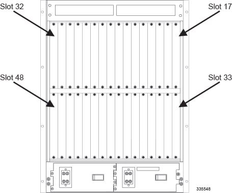
The 10 Gigabit Ethernet Line Card is a full-height line card that occupies the upper and lower slots in the chassis. When referring to installed XGLCs, use the upper slot number only. Slot numbering for other installed half-height cards is maintained: 17 to 32 and 33 to 48, regardless of the number of installed XGLCs
| Position | Slot Number | |||||||||||||||
|---|---|---|---|---|---|---|---|---|---|---|---|---|---|---|---|---|
|
Front |
16 |
15 |
14 |
13 |
12 |
11 |
10 |
9 |
8 |
7 |
6 |
5 |
4 |
3 |
2 |
1 |
|
Rear Top Slots |
32 |
31 |
30 |
29 |
28 |
27 |
26 |
25 |
24 |
23 |
22 |
21 |
20 |
19 |
18 |
17 |
|
Rear Bottom Slots |
48 |
47 |
46 |
45 |
44 |
43 |
42 |
41 |
40 |
39 |
38 |
37 |
36 |
35 |
34 |
33 |
The following line cards are available for the chassis:
- Switch Processor Input/Output (SPIO) Card: SPIOs are installed in chassis slots 24 and 25 behind SMCs. SPIOs provide interfaces for local and remote management, Central Office (CO) alarming, and eventually, Building Integrated Timing Supply (BITS) timing.
- Fast Ethernet Line Card (FLC2): FLC2s are installed directly behind their corresponding packet processing cards. Each card provides eight 10/100Base-T RJ-45 Ethernet interfaces that are used as either the R-P or the Pi interfaces for the 3G wireless data application.
- Gigabit Ethernet Line Card (GLC2): GLC2s are installed directly behind their corresponding packet processing cards. Each card provides a single 802.3z-compliant gigabit Ethernet converter with a Small Form-factor Pluggable (SFP) module. Supported modules provide optical or copper interfaces.
- Quad Gigabit Ethernet Line Card (QGLC): QGLCs are installed directly behind their corresponding packet processing cards. Each card provides four 802.3z-compliant gigabit Ethernet interfaces with a Small Form-factor Pluggable (SFP) module. Supported modules provide fiber or copper connectors.
- 10 Gigabit Ethernet Line Card (XGLC): XGLCs are a single-port full-height line card installed directly behind their corresponding packet processing cards. The cards support 10 gigabit Ethernet interfaces using industry-standard SFP+ modules. Various fiber types may be used as required.
- Optical (ATM) Line Cards (OLC 2): Four-port OLC2s are installed directly behind their corresponding packet processing cards. Each card provides four LC duplex ports that accept small SFP modules and supports either single-mode or multi-mode fiber optic cable.
- Channelized (STM-1/OC-3) Line Cards (CLC2): Four-port CLC2s are installed directly behind their corresponding packet processing cards. The CLC2 provides four LC duplex ports. The ports accept one of two types of Small Form-factor Pluggable (SFP) modules. The SFP type relates to the type of fiber optic cable—single-mode or multi-mode.
- Redundant Crossbar Card (RCC): RCCs are installed in the lower-middle two slots, directly behind the SMCs. RCCs provide a redundant data and control path link between each line card and all packet processing cards. There are no external interfaces on the RCC. Internally, it provides redundant 5 Gbps serial links to each packet processing card and line card.
| Line Card Type | Chassis Slot Number | Description |
|---|---|---|
|
Switch Processor Input/Output (SPIO) |
24 |
Resides behind Primary SMC in slot 8. |
|
25 |
Resides behind Redundant SMC in slot 9. |
|
|
Redundancy Crossbar Card (RCC) |
40 |
Resides behind Primary SMC in slot 8. It provides redundancy for all packet processing application cards and for line cards installed in the upper-rear chassis, slots 17 through 23 and 26 through 32. |
|
41 |
Resides behind Redundant SMC in slot 9. It provides redundancy for all SMC application cards and for line cards installed in the lower-rear chassis, slots 33 through 39 and 42 through 48. |
|
|
Ethernet 10/100 (FLC2) |
17 through 23, 26 through 39, or 42 through 48 |
Resides directly behind its corresponding packet processing card. Each packet processing card can support up to two FLC2s. The active card is installed in the upper rear chassis slot. The redundant card is installed in the lower rear chassis slot. |
|
Ethernet 1000 (GLC2) |
17 through 23, 26 through 39, or 42 through 48 |
Resides directly behind its corresponding packet processing card. Each packet processing card can support up to two GLC2s. The active card is installed in the upper rear chassis slot. The redundant card is installed in the lower rear chassis slot. |
|
Quad Gig-E (QGLC) |
17 through 23, 26 through 39, or 42 through 48 |
Resides directly behind its corresponding packet processing card. Each packet processing card can support up to two QGLCs. The active card is installed in the upper rear chassis slot. The redundant card is installed in the lower rear chassis slot. |
|
10 Gigabit Ethernet Card (XGLC) |
17 through 23 and 26 through 32 |
Resides directly behind its corresponding packet processing card. The XGLC is a full-height line card that occupies the upper and lower slots in the ASR 5000. |
|
Optical (ATM) (OLC2) |
17 through 23, 26 through 39, or 42 through 48 |
Resides directly behind its corresponding packet processing card. Each packet processing card can support up to two OLC2s. The active card is installed in the upper rear chassis slot. The redundant card is installed in the lower rear chassis slot. |
|
Channelized (CLC2) |
7 through 23, 26 through 39, or 42 through 48 |
Resides directly behind its corresponding packet processing card. Each packet processing card can support up to two CLC2s. The active card is installed in the upper rear chassis slot. The redundant card is installed in the lower rear chassis slot. |
Line Card Redundancy
To optimize network efficiency and minimize down time, the system supports 1:1 redundancy for OLC2s, CLC2s, FLC2s, GLC2s, and QGLCs.
With the exception of the XGLC, line cards are installed in the half-height slots at the rear of the chassis. This design allows two Ethernet or two Optical (ATM) or two Channelized line cards directly behind (one top, one bottom) every packet processing card that normally operates in active mode.
When two line cards are installed, the card in the upper-rear chassis slot is automatically the active card. The card in the lower-rear chassis slot is automatically placed in standby mode. In the event that the active card experiences a failure, the system automatically migrates traffic to the standby card in the lower slot.
Side-by-side Redundancy for the XGLC
The XGLC is a full-height card that requires both top and bottom line card slots for a single 10-Gigabit port. To achieve one-to-one line card redundancy, you must install two XGLCs in adjacent slots. Otherwise, you configure port and card redundancy for the XGLCs in the same way as other line cards. There are no restrictions that prevent the side-to-side 1:1 XGLC redundant arrangement from functioning with other Ethernet line card types.
An active packet processing card must always be installed behind an XGLC. Monitoring functions occur in a distributed fashion. Select the XGLCs that act as a redundant pair via the CLI. Configure the redundant pairs prior to configuring the interface bindings so that proper parallel physical and logical port configurations are established. The card redundancy and monitoring begins as soon as the packet processing card in front is active.
The packet processing cards behind a pair of redundant XGLCs must always be in Active mode.
Requirement Summary
There must be a direct connection to a packet processing card behind each side-by-side redundant XGLC pair.
17 – 18
19 – 20
21 – 22
23 – 26 (SPIOs 24 and 25 are skipped in this line card redundancy model)
27 – 28
29 – 30
31 – 32
Use only the top line card slot numbers to configure XGLC 1:1 redundancy.
CLI Commands for XGLC Redundancy
Side-by-side 1:1 redundancy only operates on top line card slot numbers: cards 17 through 23 and 26 through 32. Make sure that both packet processing cards in front of the line cards are of the same type, configured as a redundant pair, and active.The CLI configuration to support this redundancy mode is specified at the card level as follows:
[local]asr5000# config
[local]asr5000(config)#  card 17
[local]asr5000(config-card-17)# redundant with 18
To remove this configuration, set the redundant card back to the default bottom line card:
[local]asr5000(config-card-17)# redundant with 33
Recommended Minimum Chassis Configuration
An absolute minimum chassis configuration consists of one packet processing card and their respective line cards. However, it is strongly recommended that redundant components be used to minimize the risk of system outage.
| Application Card | Application Card Slot Number | Associated Interface Card | Line Card Slot Number |
|---|---|---|---|
SMC |
8 |
SPIO |
24 |
RCC |
40 |
||
Redundant SMC |
9 |
SPIO |
25 |
RCC |
41 |
||
PSCA, PSC2, PSC3 or PPC Note that for Release 9.0, only PDSN and HA are supported on the PPC. Note that for Release 10.0, only PDSN, HA, and GGSN are supported on the PPC. |
2 |
FLC2 or QGLC |
18 and 34 |
Redundant FLC2 or QGLC |
|||
XGLC |
17 and 32 |
||
PSCA, PSC2, PSC3 or PPC |
3* |
None required |
N/A |
PSCA, PSC2, PSC3 or PPC |
4 |
None required |
N/A |
Redundant PSCA, PSC2, PSC3 or PPC |
11 |
None required |
N/A |
* Minimum requirement for hardware + software redundancy or combined services on a single platform.
Installing Half-Height Line Cards
This section provides instructions for adding half-height line cards to the chassis.
 Caution | During installation, maintenance, and/or removal, wear a grounding wrist strap to avoid ESD damage to the components. Failure to do so could result in damage to sensitive electronic components and potentially void your warranty. |
The XGLC is a full-height line card that takes up the upper and lower slots in the back of the chassis.
| Step 1 | Determine the type of line card you are installing. Each line card is identified by the text near the bottom of its front panel. | ||
| Step 2 | Determine which chassis slot to install the card in based on the information in Chassis Slot Numbering and Assignments. | ||
| Step 3 | Remove the blanking panel covering the slot, if one is installed. | ||
| Step 4 | Slide the interlock fully downward on the card. Flip the ejector levers outward and away from the face plate. | ||
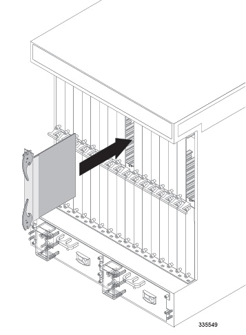
| Step 5 | Hold the card by
its ejector levers and align the card with the upper and lower card guides of
the chassis slot. Gently slide it into the slot until the levers touch the
chassis frame.
| ||
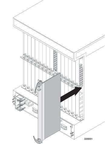
| Step 6 | Push the ejector levers inward firmly until the card is firmly seated in the chassis midplane and the ejector levers can be pushed in no further. Press firmly on the card's faceplate to ensure that it is fully seated. The card's front panel should be flush against the chassis' upper and lower card mounts for the slot. | ||
| Step 7 | Slide the
interlock switch on the front panel of the line card upward to lock the ejector
tab in place. The flange on the left-side of the interlock switch prevents
movement of the ejector tab when raised completely.
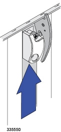
You must slide the interlock switch upward before securing the card's top screw to the mounting rail. | ||
| Step 8 | Use a Phillips #2 screwdriver to tighten the screws at the top and bottom of the line card's front panel to secure the card to the chassis. | ||
| Step 9 | Repeat step 1 through step 7 to install other line cards. | ||
| Step 10 | Install blanking
panels over any unused chassis slots.
| ||
| Step 11 | Proceed to the appropriate chapter for information on connecting data cables to the line cards. |
Installing the 10 Gigabit Ethernet Line Card (XGLC)
The XGLC is a full-height line card that gets installed in the rear slots of the ASR 5000 chassis. It provides a single Small Form-factor Pluggable+ (SFP+) 10 Gigabit Ethernet interface for network connectivity.
XGLC SR accepts a 10GBase-SR module that drives optical fiber with a center wavelength of 850nm terminated by an LC optical connector. The module can drive optical signals up to 300 meters using 50/125um fiber (MMF), and up to 33 meters using 62.5/125um fiber (MMF).
XGLC LR accepts a 10GBase-LR module that drives optical fiber with a center wavelength of 1310nm terminated by an LC optical connector. This module can drive optical signals up to 10 kilometers using 50/125um fiber (SMF).
XGLCs are installed behind packet processing cards. You can install a maximum of twelve XGLCs in the chassis.
Preparing a Full-height Line Card Slot
The full-height XGLC requires two line card slots: an upper chassis slot and the lower chassis slot directly beneath it. For example, if a PSC2 is installed in slot 1, its corresponding XGLC would be installed in slots 17 and 33.
When entering the slot location of an XGLC in a CLI command use the upper slot number only.
The procedure for modifying two half-height card slots to accept the full-height XGLC is described in the Preparing A Full-Height Card Slot appendix. Complete the procedures described in that appendix before attempting to install the XGLC in the ASR 5000 chassis.
Installing the XGLC
Caution | During installation, maintenance, and/or removal, wear a grounding wrist strap to avoid ESD damage to the components. Failure to do so could result in damage to sensitive electronic components and potentially void your warranty. |
 Feedback