- About this Guide
- ASR 5000 Hardware Platform Overview
- Installation Procedure Overview
- Chassis Installation
- Application Card Installation
- Line Card Installation
- Cabling the Switch Processor Input/Output Line Card
- Cabling the Fast Ethernet (10/100) Line Card
- Cabling the Gigabit Ethernet Line Cards
- Cabling the Optical (ATM) Line Cards
- Cabling the Channelized Line Cards
- Cabling the Power Filter Units
- Applying Power and Verifying the Installation
- System Monitoring
- Adding Application and Line Cards to an Existing Installation
- Removing and Installing SMC PC Cards
- Replacing the Chassis Air Filter
- Replacing a Power Filter Unit
- Replacing Upper or Lower Fan Tray
- Replacing Application Cards
- Replacing Line Cards
- Technical Specifications
- Safety, Electrical and EMC Certifications
- Environmental Specifications
- Hardware Product Support Matrix
- Preparing a Full-Height Line Card Slot
- RMA Shipping Procedures
- Spare Component Recommendations
Preparing a Full-Height Line Card Slot
This appendix describes how to modify two vertical half-height line card slots to accept full-height line cards, such as the XGLC.
It includes the following sections:
Introduction
The ASR 5000 chassis ships with all rear line card slots configured for half-height line cards. If you are installing a full-height line card, such as the XGLC, you must prepare a full-height slot to receive it.
Full-height line cards occupy two half-height slots: an upper chassis slot and the lower chassis slot directly beneath it. For example, if a PSC2 is installed in slot 1, its corresponding XGLC would be installed in slots 17 and 33.
When entering the slot location of a full-height line card in a CLI command use the upper slot number only.
 Caution | During installation, maintenance, and/or removal, wear a grounding wrist strap to avoid ESD damage to the components. Failure to do so could result in damage to sensitive electronic components and potentially void your warranty. |
Remove Blanking Panels
You must remove the half-height blanking panels covering the upper and lower chassis slots, if installed.
| Step 1 | Identify the chassis slots in which the full-height line card will be installed. | ||
| Step 2 | Use a Phillips #2 screwdriver to loosen the screws at the top and bottom of the blanking panel. Hold the screws on the blanking panel, and pull the blanking panel away from the chassis to expose the chassis slot. | ||
| Step 3 | Repeat step 2 to remove
the half-height blanking panel covering the chassis slot directly
below the slot exposed in the previous step.
|
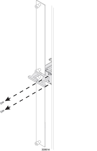
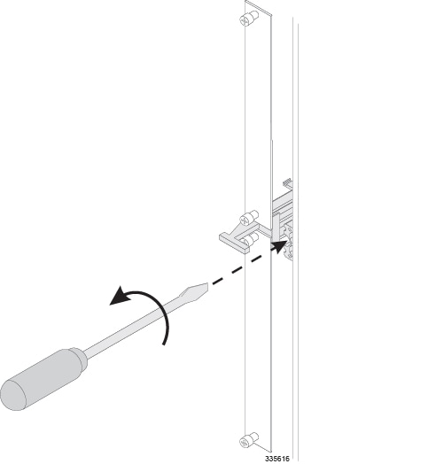
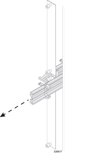
Remove the Half-Height Card Guide
You must next remove the half-height card guide separating the exposed upper and lower chassis slots.
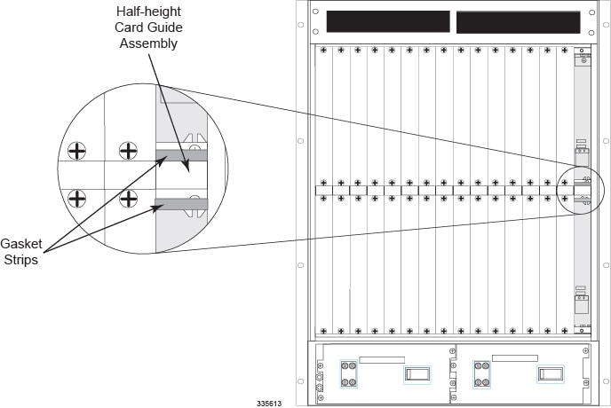
Save all of the items you remove in this step in the event that you wish to re-populate these slots with half-height cards at a later time.

 Feedback