- About this Guide
- ASR 5000 Hardware Platform Overview
- Installation Procedure Overview
- Chassis Installation
- Application Card Installation
- Line Card Installation
- Cabling the Switch Processor Input/Output Line Card
- Cabling the Fast Ethernet (10/100) Line Card
- Cabling the Gigabit Ethernet Line Cards
- Cabling the Optical (ATM) Line Cards
- Cabling the Channelized Line Cards
- Cabling the Power Filter Units
- Applying Power and Verifying the Installation
- System Monitoring
- Adding Application and Line Cards to an Existing Installation
- Removing and Installing SMC PC Cards
- Replacing the Chassis Air Filter
- Replacing a Power Filter Unit
- Replacing Upper or Lower Fan Tray
- Replacing Application Cards
- Replacing Line Cards
- Technical Specifications
- Safety, Electrical and EMC Certifications
- Environmental Specifications
- Hardware Product Support Matrix
- Preparing a Full-Height Line Card Slot
- RMA Shipping Procedures
- Spare Component Recommendations
Cabling the Power Filter Units
This chapter provides information and instructions for applying the power supply and return cables to the Power Filter Units (PFUs) .
This chapter includes the following sections:
Power Considerations
Each chassis supports one or two 165-amp PFUs.
 Note | These requirements are guidelines to assure that the cabling for your system meets safety requirements. |
| Characteristic | Value |
|---|---|
Input Voltage |
Maximum range: -40VDC to -60VDC Nominal range: -48VDC to -60 VDC |
TUV Rated Peak Current Load |
165A @ -48 VDC |
Maximum Peak Power Load |
5760W |
Empty Chassis Maximum Power Load (includes fan trays) |
800W |
Line Card (rear-installed) Maximum Power Load |
SPIO: 15W FLC2: 13.5W GLC2: 10.5W RCC: 20W QGLC: 15W XGLC: 25W OLC2: 23W CLC2: 23W |
Application Card (front-installed) Maximum Power Load |
SMC: 130W PSC: 250W PSC2: 325W PSC3: 330W PPC: 275W |
Power Feed |
PFU: 165 Amps |
Estimating Power Requirements
Use the following formula to estimate the total power consumption for each deployed chassis:
(Total Application Card Maximum Power Load) + (Total Line Card Maximum Power Load) + (Chassis Maximum Power Load)
The calculation for estimating the power required for an ASR 5000 installation with 3 PSCs, 2 SMCs, 2 SPIOs, 2 RCCs, and 4 Ethernet 1000 line cards is as follows:
(250W x 3) + (130W x 2) + ((20W x 2) + (13.5W x 4)) + 800W = 1934W
Power Cable Requirements
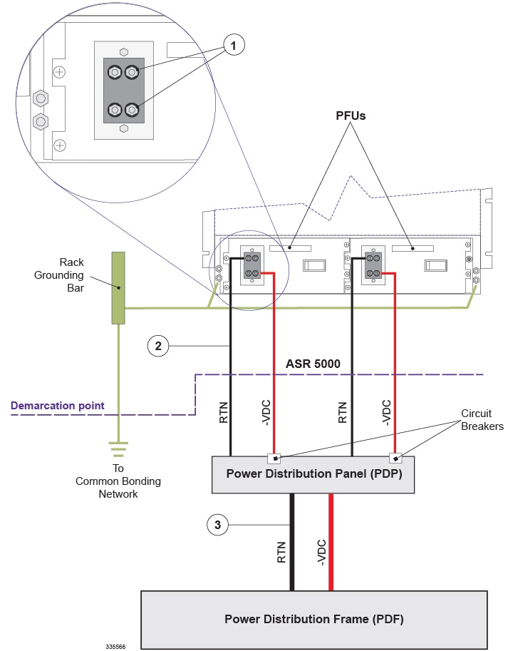
You can install up to three chassis in an equipment rack or telecommunications cabinet. Typically power cabling is run from the office Power Distribution Frame (PDF) to a Power Distribution Panel (PDP) installed in the rack or cabinet and then to each of the chassis. Due to the required bending radius at each of the system's PFUs, distributing power through a PDP allows you to use a smaller, more flexible cable for each chassis.
| Termination | Conductor Sizing Information |
|---|---|
| PDF to Fuse Panel |
Assuming an 80-foot (24 meter) loop length, each cable between the PDF and PDP must be the equivalent of 350,000 circular mils or greater. Calculations assume a 0.3 volt drop from the PDF to the PDP, and a 0.3 volt drop from the PDP to the chassis. This is a total voltage drop of 0.6 volts. |
| Fuse Panel to ASR 5000 |
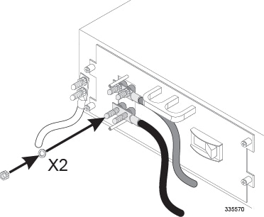
Assuming an 18-foot (5.5 meter) loop length, each cable between the PDP and the chassis must be the equivalent of 83,690 circular mils (1 AWG) or greater. Use high-flex cable. Calculations assume a 0.3 volt drop from the PDF to the PDP, and 0.3 volt drop from the fuse panel to the chassis. This is a total voltage drop of 0.6 volts. The following figure and table provide details for wiring the PFUs. |
| Item | Description | ||
|---|---|---|---|
|
1 |
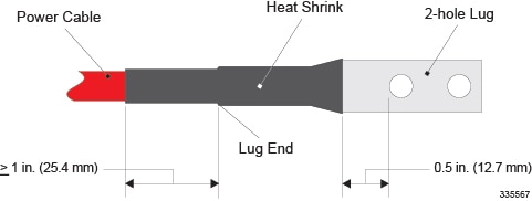
Two 2-hole lugs are required: one for return (RTN) and one for power (-VDC). The PFU 0.3125-inch posts spaced 0.88-inch on center. Method of connection: PFU - Flat Washer - Lug - Lock-Washer - Nut (9/16-inch). The nut(s) must be torqued to 50 in-lb. (5.65 N-m). The lug must be covered with heat shrink tubing. The heat shrink tubing should begin approximately 1 inch (25.4 mm) before the lug and extend to within 0.5 inch (12.7 mm) of the lugs first hole. Slide the tubing over the cable end before crimping the lug to the cable. Refer to the following figure. Use the Panduit® lugs supplied with the chassis (LCD1-56C-E). Crimp them to the cable ends with a Panduit crimp tool part number CT-920 (die color: green P37 (CD-920-1).
|
||
|
2 |
Power Cables (PDP-to-Chassis): Cable length: Not more than 9 feet (2.7 meters) one way Voltage drop: 0.3v Cable size: 1 AWG or greater |
||
|
3 |
Power Cables (PDF-to-PDP): Cable length: not more than 40 feet (12.2 meters) one way Voltage drop: 0.3v Cable size: 350,000 Circular Mils |
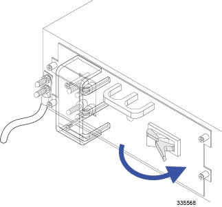
Connecting the PFU to the Power Source
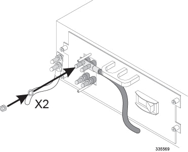
Follow the instructions in this section to connect the PFU(s) to the power source.
Each of the four power terminals is shipped with nuts and washers. The PFU has one lock-washer and one flat washer.
Note | Verify that the power source from the fuse panel is OFF before attaching power cables to the PFU(s) installed in the chassis. Spannungsversorgung abschalten vor Anschluss der Kabel an die Netzteile, um einen elektrischen Schlag zu vermeiden. |
 Feedback