Cisco Optical Automation Solution for NCS 2000 Networks, Release 26.1.1

PDF

Cisco Optical Automation Solution for NCS 2000 Networks, Release 26.1.1

Create Cisco Optical Site Manager instances and onboard SVO card host nodes

Want to summarize with AI?

Log in

Create Cisco Optical Site Manager instances and onboard the NCS 2000 nodes that host SVO cards to establish the first managed sites.


Use this topic to create Cisco Optical Site Manager instances and onboard NCS 2000 nodes that host SVO cards. Complete instance creation, web UI access, authorization group setup, node onboarding, and initial configuration before adding more managed devices.

Cisco Optical Site Manager instance and node onboarding plan

This workflow includes the creation of Cisco Optical Site Manager instances and the onboarding of NCS 2000 nodes. The objective is to enable Cisco Optical Site Manager-based management of network elements. These activities are performed:

  • Creation of Cisco Optical Site Manager instances via Admin Plane

  • Access to Cisco Optical Site Manager web UI

  • Configuration of authorization groups

  • Onboarding of NCS 2000 nodes

  • Initial system configuration (e.g., NTP)

The onboarding must be completed for the primary ROADM node before adding any additional devices.

Cisco Optical Site Manager instance and node onboarding verification

At the end of this workflow, Cisco Optical Site Manager instances and SVO cards are installed as planned, and all related Cisco Optical Site Manager instances are up and running.


Create Cisco Optical Site Manager instances

Create a Cisco Optical Site Manager instance using the Admin Plane web UI.
Note

The instance name and IP address cannot be modified after creation. The TDM terminology must match the node configuration.

Follow these steps to create Cisco Optical Site Manager instances.

Procedure

  1. Access the Admin Plane web UI.

  2. Open the Instances panel.

  3. Click the + icon.

  4. Enter the required parameters:

    The product workflow is documented in: Create a Cisco Optical Site Manager instance.

    • Name (must be unique)

    • Software Version

    • TDM Terminology

    • Type (ROADM or OLA)

    • Reserved Memory

    • Username / Password

    • IPv4 Address

  5. Click Create.

The Cisco Optical Site Manager instance is created and appears in RUNNING / UP state.

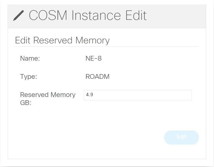
Later on clicking on the pencil it is possible to modify the Reserved Memory

Figure 1. Edit memory size

What to do next

Reserve memory according to the sizing guidelines before you create additional Cisco Optical Site Manager instances.


Access the Cisco Optical Site Manager web UI

Access the Cisco Optical Site Manager web UI.
Note

The Cisco Optical Site Manager web UI is accessible only after the instance is in RUNNING / UP state. Use the credentials defined during the Add Instance step.

Follow these steps to access the Cisco Optical Site Manager web UI.

Procedure

  1. Open a web browser.

  2. Connect to the Cisco Optical Site Manager web UI using one of these methods:

    • From the Admin Plane: click the hyperlink in the "IP Addresses" column of the instance

    • Directly from browser: https://<COSM_IP_ADDRESS>

  3. Enter the username and password defined during Cisco Optical Site Manager instance creation.

  4. Click Login.

    This figure shows the Cisco Optical Site Manager web UI login window.

    Figure 2. Cisco Optical Site Manager web UI login window

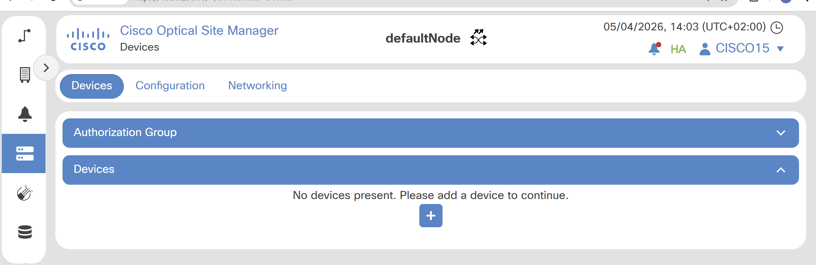
The Cisco Optical Site Manager web UI landing page is displayed.

Figure 3. Cisco Optical Site Manager landing page (before device onboarding)

What to do next

Use the Cisco Optical Site Manager web UI for device management and configuration tasks.


Create Cisco Optical Site Manager authorization groups

Create an authorization group to allow Cisco Optical Site Manager to access NCS 2000 nodes.
Note

An authorization group is required for Cisco Optical Site Manager to access NCS 2000 devices. If Cisco Optical Site Manager onboards only one device that uses one credential set, one authorization group is sufficient.

Follow these steps to create Cisco Optical Site Manager authorization groups.

Procedure

  1. Access the Cisco Optical Site Manager web UI.

  2. Open the Devices page.

  3. Choose Devices > Authorization Group > Username and Password.

  4. Click the +.

  5. Enter these parameters:

    For the supporting workflow, see: Create or edit an authorization group.

    • Auth Group Name: logical name of the Authorization Group

    • Remote Username: username configured on the NCS 2000 node

    • Remote Password: password configured on the NCS 2000 node

    • Save the configuration

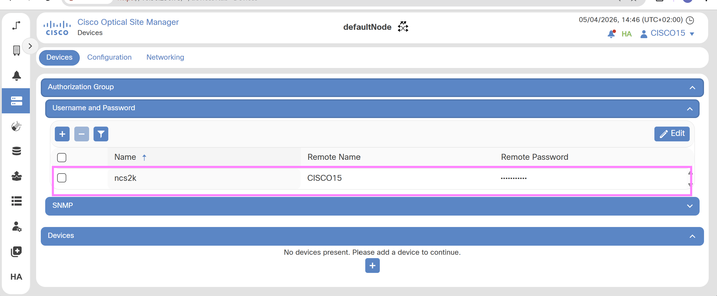
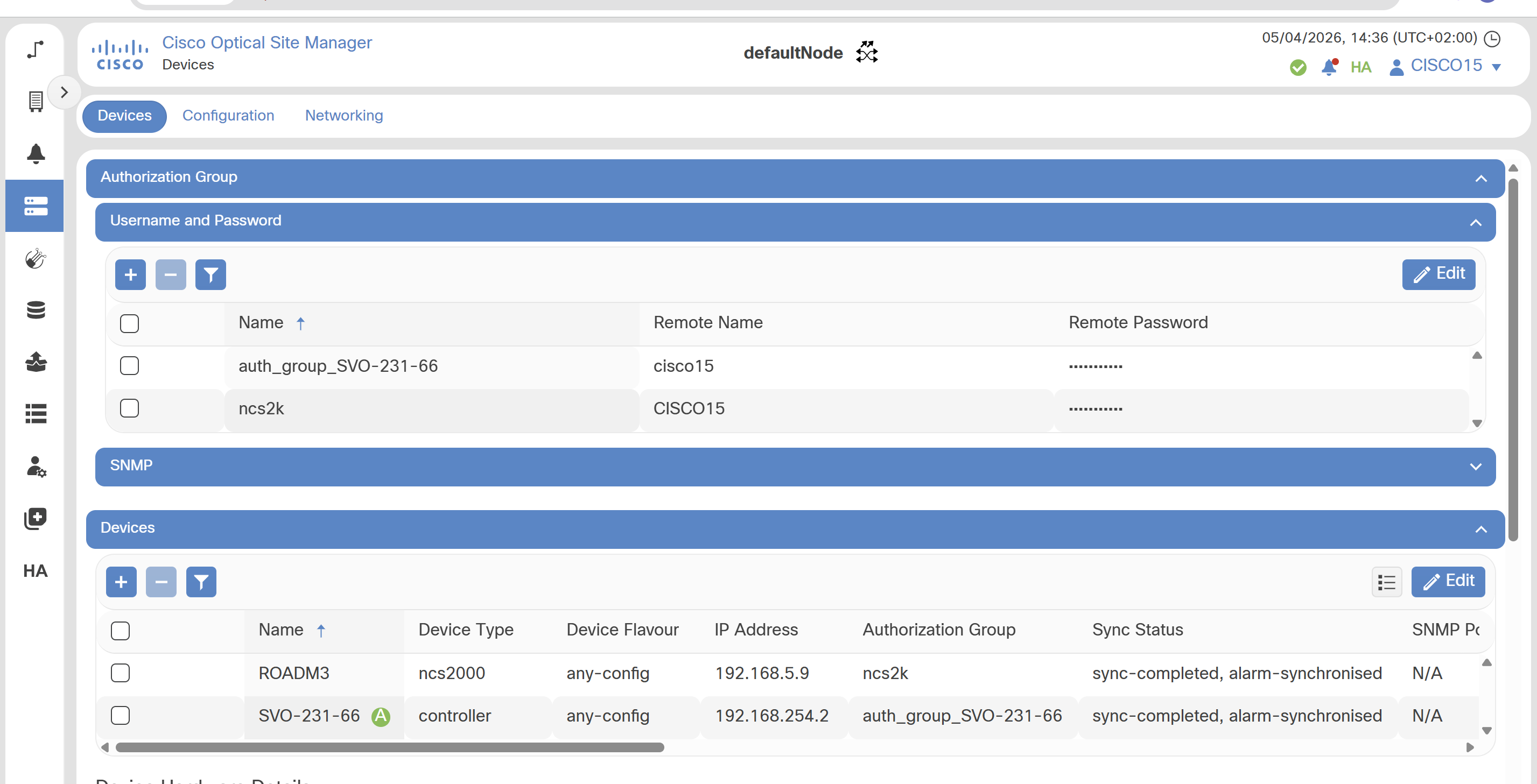
The Authorization Group is successfully created and appears in the Authorization Group list.

Figure 4. Authorization group creation

What to do next

  • Verify that the credentials in the authorization group match the credentials configured on the NCS 2000 node.

  • Create additional authorization groups when multiple devices use different credentials.

  • Use the same procedure to create authorization groups for NCS 1000 devices.


Onboard ROADM nodes that host SVO cards

Add the ROADM node that hosts the SVO card to the Cisco Optical Site Manager instance.
Note

The device name and device flavor cannot be modified after creation.

Follow these steps to onboard ROADM nodes that host SVO cards.

Procedure

  1. Access the Cisco Optical Site Manager web UI.

  2. Choose Devices > Devices.

  3. Click the + icon to open the Add Device dialog.

  4. Enter:

    Cisco documents the workflow in: Add a device.

    • Device Type: ncs2000

    • Device Flavour: any-config

    • Device Name

    • IP Address

    • Auth Group

  5. Click Add to start the onboarding process.

The device is successfully added to the Cisco Optical Site Manager instance and appears in the device list.

Immediately after onboarding, the Sync Status is "sync-not-started, out-of-sync".

Device synchronization may take several minutes, and large nodes may take 30 to 40 minutes.

Wait until the Sync Status becomes "sync-completed, alarm-synchronized".

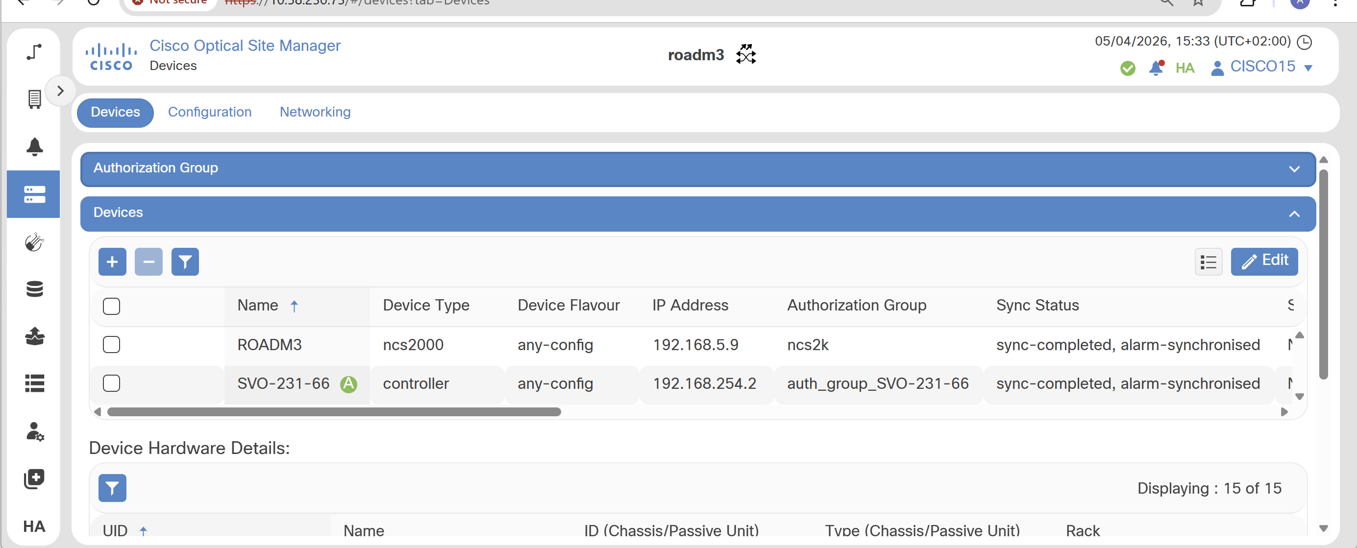
Because the ROADM hosts an SVO card, a controller device type appears automatically in the list. The name is taken from the YAML file.

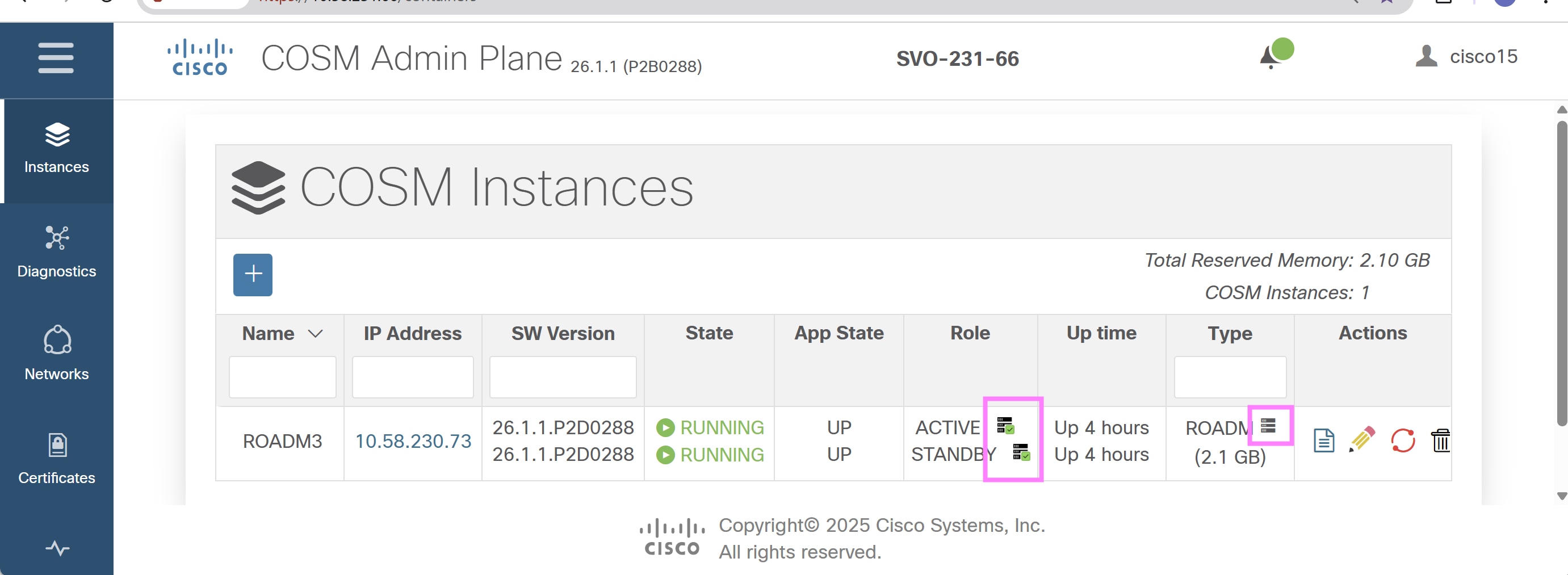
In the Admin Plane, the SVO instances show that the devices are reachable and that the SVO card is discovered.

Figure 5. ROADM hosting SVO card

What to do next

  • Delete and add the device again if the device name or device flavor is configured incorrectly.

  • Change the display name from the Cisco Optical Site Manager web UI settings, if needed.

  • Verify the node name in Cisco Optical Network Controller after Cisco Optical Site Manager onboarding completes.


Adjust SVO card authorization groups

Update the automatically created authorization group for SVO cards.

Follow these steps to adjust SVO card authorization groups.

Procedure

  1. Choose Devices > Authorization Group.

  2. Identify the SVO card Authorization Group.

    Refer to the product procedure: Create or edit an authorization group.

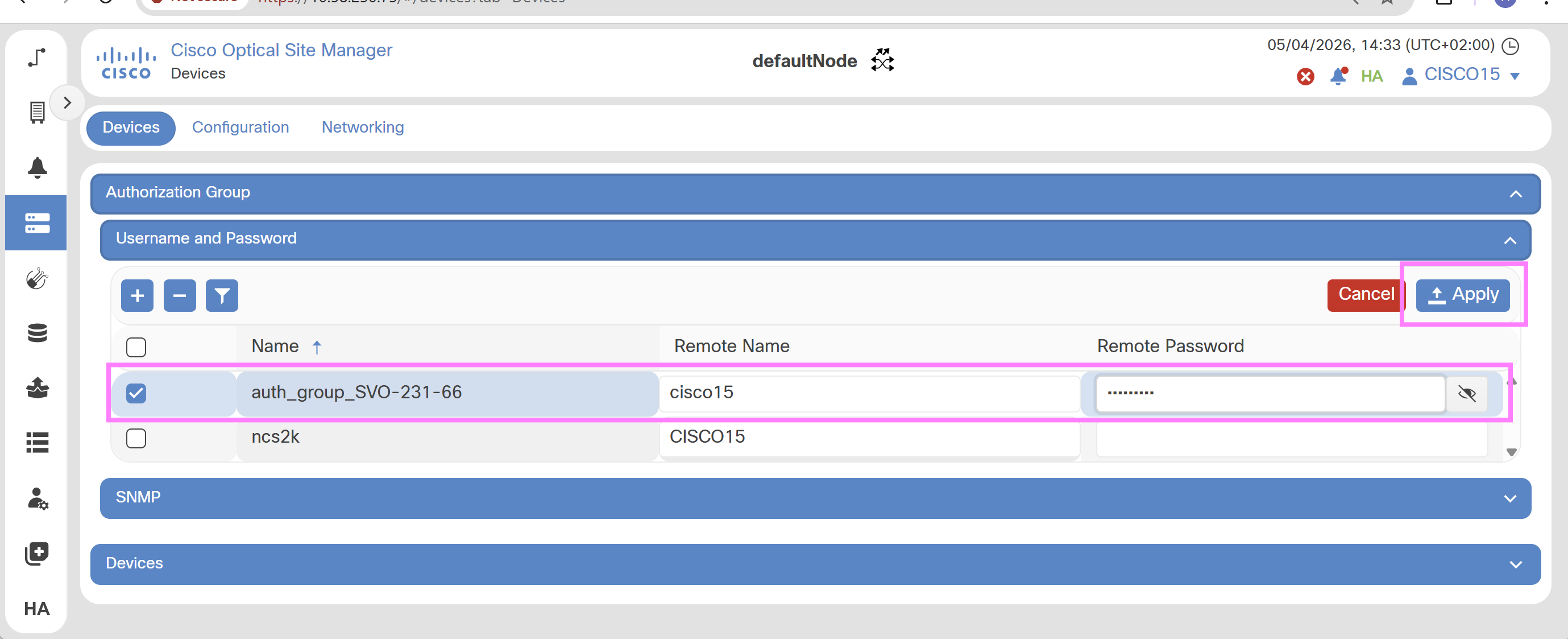
  3. Edit the Remote Name and Remote Password. Password must match the admin plane credential configured during SVO setup.

  4. Apply.

    Figure 6. SVO card authorization group editing

The SVO card authorization group is correctly configured, and the Sync Status is "sync-completed, alarm-synchronized".

Figure 7. SVO card authorization group editing

Configure SVO card NTP servers

Configure Network Time Synchronization (NTP) on SVO cards and Cisco Optical Site Manager instances to ensure consistent system time across the network. Time synchronization is required to guarantee:

This procedure configures the NTP server address for the SVO card onboarded by the Cisco Optical Site Manager instance on which the procedure is performed.

In a Geo HA configuration, repeat the procedure on both Cisco Optical Site Manager instances that onboard the SVO cards because one SVO card does not automatically synchronize its NTP configuration with the other.

NTP server configuration is required only for Cisco Optical Site Manager instances that onboard SVO cards. The configuration is allowed on an instance that does not onboard an SVO card, but it has no effect.

Follow these steps to configure SVO card NTP servers.

Procedure

  1. Access the node web UI.

  2. Choose Settings > NTP.

  3. Click Edit to enable configuration.

  4. Enter these parameters:

    • Server Address: IP address of the primary NTP server

    • Backup Server Address: IP address of the secondary NTP server

  5. Click Apply.

  6. Confirm the operation by clicking Yes.

  7. Repeat on both Cisco Optical Site Manager Instances in case of Geo HA.

The node successfully synchronizes its date and time with the configured NTP server.

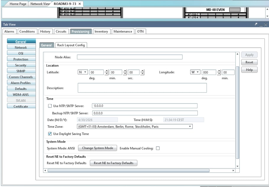
NTP in NCS 2000/CTP

Setting of NTP server IP address configured in Cisco Optical Site Manager web UI, is not applied NCS 2000.

Key Points when NTP Server is configured in NCS 2000

  • The NCS 2000 node always attempts synchronization with the primary NTP server first

  • If the primary server is unreachable, the backup server is used

  • If both servers are unreachable, an SNTP-FAIL alarm is raised

  • The system retries synchronization periodically and updates the time at regular intervals

  • The SNTP-FAIL alarm is automatically cleared once synchronization is restored

Accurate time synchronization is required for:

  • Alarm correlation

  • Log consistency

  • Network-wide coordination

Key Points when NTP Server is NOT configured in NCS 2000

The NCS 2000 node does not contact any NTP server and receives time every 20 minutes from Cisco Optical Site Manager.

Figure 8. NCS 2000 NTP server not configured in CTC

Onboard devices in Cisco Optical Site Manager using XML

Prepare an XML configuration file and upload it to Cisco Optical Site Manager to create authorization groups, assign UIDs, and add devices. For details, see XML examples for Cisco Optical Site Manager onboarding.

The XML file can include authorization groups such as ncs2k and auth_group_SVO-231-66, along with the device information required for onboarding.

Follow these steps to onboard devices in Cisco Optical Site Manager using XML.

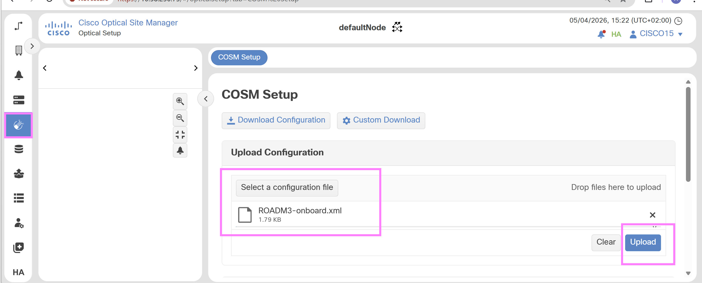
Procedure

  1. Access the node web UI.

  2. Choose Optical Setup > Cisco Optical Site Manager Setup.

  3. Select a configuration file.

  4. Click Upload.

    Figure 9. ROADM device XML onboarding upload

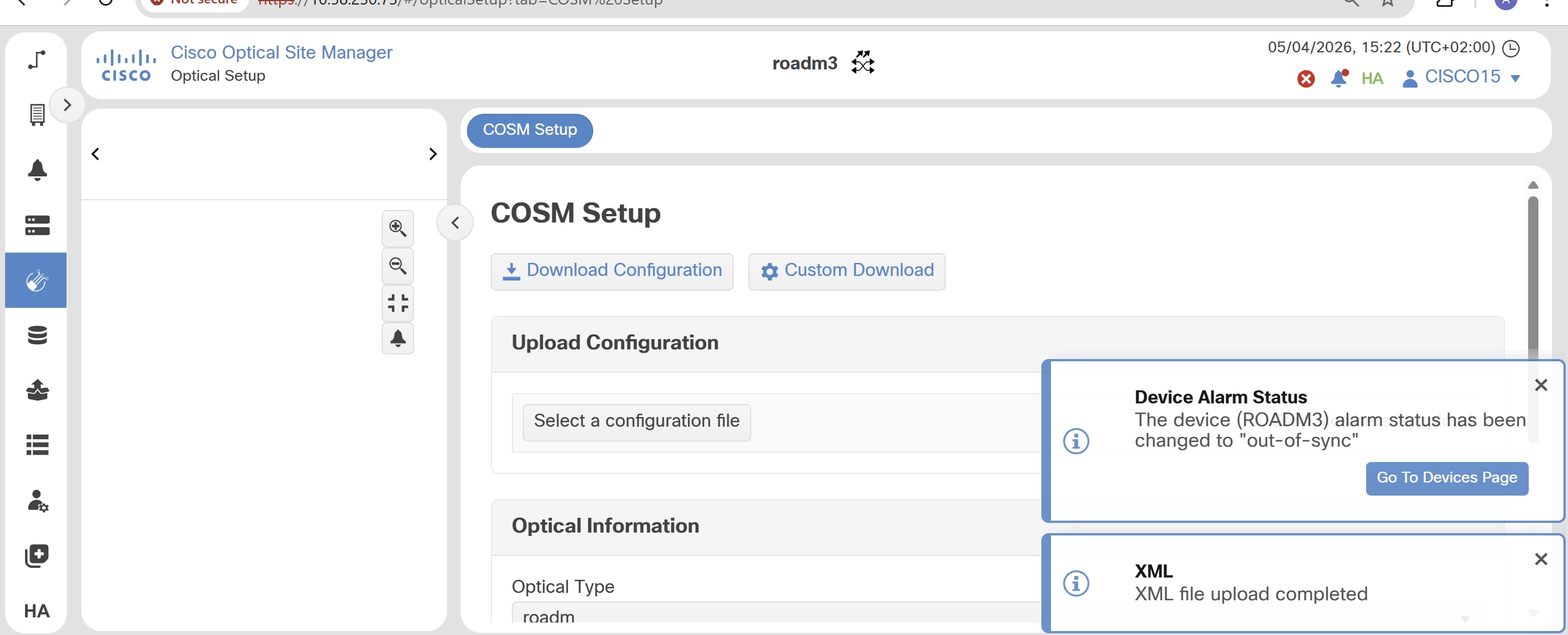
The device is successfully added to the Cisco Optical Site Manager instance and appears in the device list. If a ROADM node hosts an SVO card, the device appears automatically in the list.

Figure 10. ROADM device XML onboarding upload completed
Figure 11. XML onboarding result

XML examples for Cisco Optical Site Manager onboarding

This XML example creates an authorization group and adds a ROADM device.
<config xmlns="http://tail-f.com/ns/config/1.0">
  <devices xmlns="http://tail-f.com/ns/ncs">
    <authgroups>
      <group>
        <name>ncs2k</name>
        <default-map>
          <remote-name>CISCO15</remote-name>
          <remote-password>otbu+123</remote-password>
        </default-map>
      </group>
    </authgroups>
  </devices>
  <nodes xmlns="http://cisco.com/yang/opt-node">
    <node>
      <id>0</id>
      <node-information>
        <name>roadm3</name>
        <optical-type xmlns:ccet="http://cisco.com/yang/optical/common-equipment-types">ccet:roadm</optical-type>
        <tdm-terminology-type xmlns:ccet="http://cisco.com/yang/optical/common-equipment-types">ccet:ansi</tdm-terminology-type>
      </node-information>
      <devices>
        <device>ROADM3-9</device>
        <address>192.168.5.9</address>
        <admin-state>unlocked</admin-state>
        <authgroup>ncs2k</authgroup>
        <device-type xmlns:cisco-ne-type="http://cisco.com/yang/ne-type">cisco-ne-type:ncs2000</device-type>
        <device-flavour xmlns:ccet="http://cisco.com/yang/optical/common-equipment-types">ccet:any-config</device-flavour>
        <first-active-chassis-uid>1</first-active-chassis-uid>
      </devices>
    </node>
  </nodes>
</config>

This extended XML example includes authorization groups, a Cisco NCS 1000 device, and UID mappings for passive units.

<config xmlns="http://tail-f.com/ns/config/1.0">
  <devices xmlns="http://tail-f.com/ns/ncs">
    <authgroups>
      <group>
        <name>ncs2k</name>
        <default-map>
          <remote-name>CISCO15</remote-name>
          <remote-password>otbu+123</remote-password>
        </default-map>
      </group>
    </authgroups>
  </devices>
  <devices xmlns="http://tail-f.com/ns/ncs">
    <authgroups>
      <group>
        <name>ncs1k</name>
        <default-map>
          <remote-name>sirius</remote-name>
          <remote-password>lablab</remote-password>
        </default-map>
      </group>
    </authgroups>
  </devices>
  <nodes xmlns="http://cisco.com/yang/opt-node">
    <node>
      <id>0</id>
      <node-information>
        <name>roadm3</name>
        <optical-type xmlns:ccet="http://cisco.com/yang/optical/common-equipment-types">ccet:roadm</optical-type>
        <tdm-terminology-type xmlns:ccet="http://cisco.com/yang/optical/common-equipment-types">ccet:ansi</tdm-terminology-type>
      </node-information>
      <devices>
        <device>ROADM3-9</device>
        <address>192.168.5.9</address>
        <admin-state>unlocked</admin-state>
        <authgroup>ncs2k</authgroup>
        <device-type xmlns:cisco-ne-type="http://cisco.com/yang/ne-type">cisco-ne-type:ncs2000</device-type>
        <device-flavour xmlns:ccet="http://cisco.com/yang/optical/common-equipment-types">ccet:any-config</device-flavour>
        <first-active-chassis-uid>1</first-active-chassis-uid>
      </devices>
      <devices>
        <device>kepler49</device>
        <address>192.168.5.49</address>
        <admin-state>unlocked</admin-state>
        <authgroup>ncs1k</authgroup>
        <device-type xmlns:cisco-ne-type="http://cisco.com/yang/ne-type">cisco-ne-type:ncs1000</device-type>
        <device-flavour xmlns:ccet="http://cisco.com/yang/optical/common-equipment-types">ccet:txp-only</device-flavour>
        <first-active-chassis-uid>20</first-active-chassis-uid>
        <netconf-port>830</netconf-port>
        <ssh-port>22</ssh-port>
      </devices>
      <passive-unit xmlns="http://cisco.com/yang/optical/inventory">
        <uid>501</uid>
        <passive-unit-id>1</passive-unit-id>
        <device>ROADM3-9</device>
        <rack-id>2</rack-id>
        <ru-position>9</ru-position>
        <slot>1</slot>
        <passive-unit-type xmlns:cet="http://cisco.com/yang/ncs2k/equipment-types">cet:NCS2K-MF-DEG-5</passive-unit-type>
      </passive-unit>
      <passive-unit xmlns="http://cisco.com/yang/optical/inventory">
        <uid>502</uid>
        <passive-unit-id>2</passive-unit-id>
        <device>ROADM3-9</device>
        <rack-id>2</rack-id>
        <ru-position>10</ru-position>
        <slot>1</slot>
        <passive-unit-type xmlns:cet="http://cisco.com/yang/ncs2k/equipment-types">cet:NCS2K-MF-UPG-4</passive-unit-type>
      </passive-unit>
      <passive-unit xmlns="http://cisco.com/yang/optical/inventory">
        <uid>503</uid>
        <passive-unit-id>3</passive-unit-id>
        <device>ROADM3-9</device>
        <rack-id>1</rack-id>
        <ru-position>4</ru-position>
        <slot>1</slot>
        <passive-unit-type xmlns:cet="http://cisco.com/yang/ncs2k/equipment-types">cet:NCS2K-MF-MPO-16LC</passive-unit-type>
      </passive-unit>
    </node>
  </nodes>
</config>