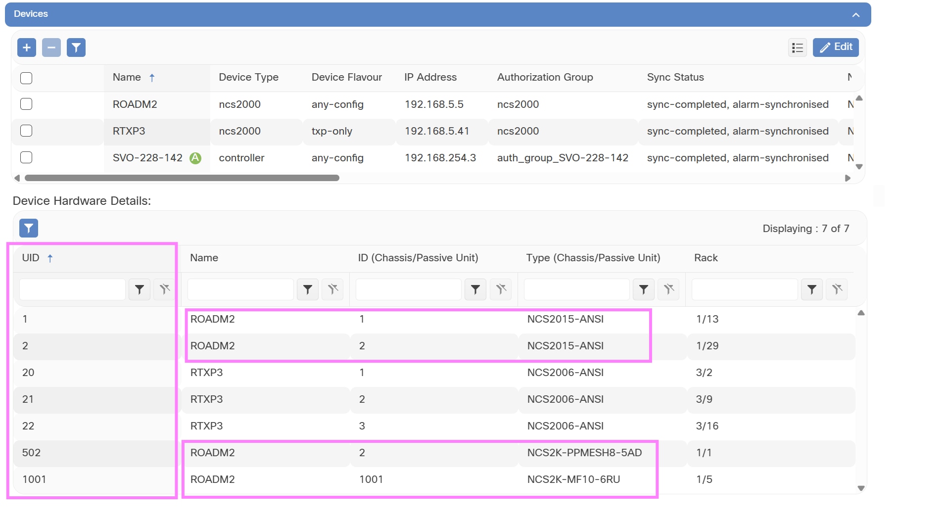
This section describes Cisco Optical Site Manager functions, deployment options, sizing considerations, networking requirements, and instance grouping for NCS 2000 and NCS 1000 environments.
Review Cisco Optical Site Manager functions, deployment models, sizing requirements, and instance grouping for NCS 2000 and NCS 1000 environments.
Cisco Optical Site Manager features and architecture
Cisco Optical Site Manager is a software application that aggregates NCS 2000 devices at a site, abstracts the site topology for controller or web UI access, and supports software-defined turn-up, operations, and maintenance.
Cisco Optical Site Manager runs on NCS 2000 SVO-LC. It can operate as a standalone local craft interface, integrate with Cisco Optical Network Controller, or provide an open NETCONF/YANG northbound interface for third-party controllers.
Cisco Optical Site Manager allows you to:
-
Aggregate site-level optical devices under a single management view.
-
View site topology, inventory, alarms, performance monitoring data, and mechanical layouts for chassis, cards, and passive devices.
-
Use operations, administration, and maintenance functions such as connection verification, loopbacks, PRBS, OTDR, and threshold crossing alerts.
-
Configure cards and modules for site-level operations.
Cisco Optical Network Controller can consume the site-level data streamed by Cisco Optical Site Manager and use it for network-level provisioning, monitoring, troubleshooting, topology views, and analytics.
For details about Cisco Optical Site Manager, see Cisco Optical Site Manager Data Sheet.
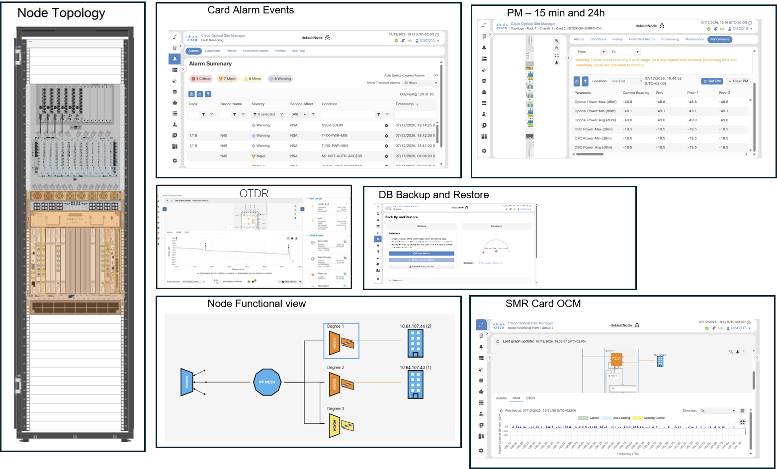
SVO card
In release 25.x and 26.x, SVO cards are required to manage NCS 2000 networks. SVO cards are installed in NCS 2000 chassis (M6, M15, or M2) and host the Cisco Optical Site Manager application.
This figure shows the SVO card front panel.

Cisco Optical Site Manager deployment models
SVO card deployments support two main models, designed to address different operational and availability requirements:
-
Standalone (SA)
The standalone deployment uses a single SVO card. This model has not been fully validated and is not recommended for production environments or demonstrations.
-
High Availability (HA)
SVO cards can be deployed using different HA configurations:
-
Local HA: two SVO cards installed in different shelves of the same ROADM.
-
Local HA (distributed): one SVO card in a ROADM and one in an external M2 chassis.
-
Geo HA (nearby-node): redundancy between SVO cards deployed on nearby NCS 2000 nodes co-located within the same site.
-
Geo HA (via UDC): geo-redundancy between SVO cards deployed on nodes in different sites and connected through UDC.
-
For HA architecture and cabling details, see the Cisco Optical Site Manager installation documentation for NCS 2000 SVO-LC.
Admin Plane and instance management
The Admin Plane is a software component that runs on the SVO card. Each SVO card has its own Admin Plane and web UI where Cisco Optical Site Manager instances are defined.
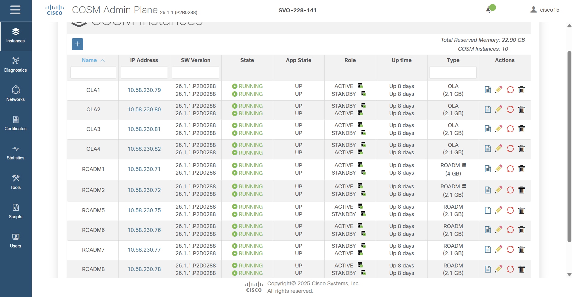
A Cisco Optical Site Manager instance runs on both SVO cards in an HA configuration, active on one card and standby on the other. A Cisco Optical Site Manager instance can be an OLA or ROADM type.
Cisco Optical Site Manager network considerations
Consider these networking aspects:
-
IP addressing
Cisco Optical Site Manager IP addresses belong to the management network, while NCS 2000 and NCS 1000 devices belong to the device network. Keep the management and device networks separate.
SVO card network YAML file
A specific YAML configuration file is required for each SVO card.
In high availability deployments, each card uses a separate file, with the only difference being the
server-nameparameter. -
SVO card cabling
Connect each SVO card to both the management network and the device network. Cabling depends on the SVO card deployment model.
Cisco Optical Site Manager sizing requirements
The memory required for each Cisco Optical Site Manager instance depends on the NCS 2000 node degree and on whether remote transponder or NCS 1000 transponders are present.
This table summarizes the Cisco Optical Site Manager minimum sizing requirements.
| Sizing | Memory |
| OLA | 2.1 GB |
| ROADM 1, 2, 3, 4 degrees | 2.1 GB |
| ROADM 5, 6, …, 12 degrees | 4 GB |
| ROADM 13, 14, 15, 16 degrees | 6 GB |
The total memory allocated per SVO card must not exceed 32 GB. For example, if a network is composed of 15 ROADMs with max 4-degree, this means a maximum of 15 Cisco Optical Site Manager instances.
These are the minimum recommended theoretical values based on the node degree (also applicable to Layer2 SMRs).
Customize values when you create the Cisco Optical Site Manager instance. See Create Cisco Optical Site Manager instances.
RAM allocation can be adjusted during Cisco Optical Site Manager instance management.
SVO card placement
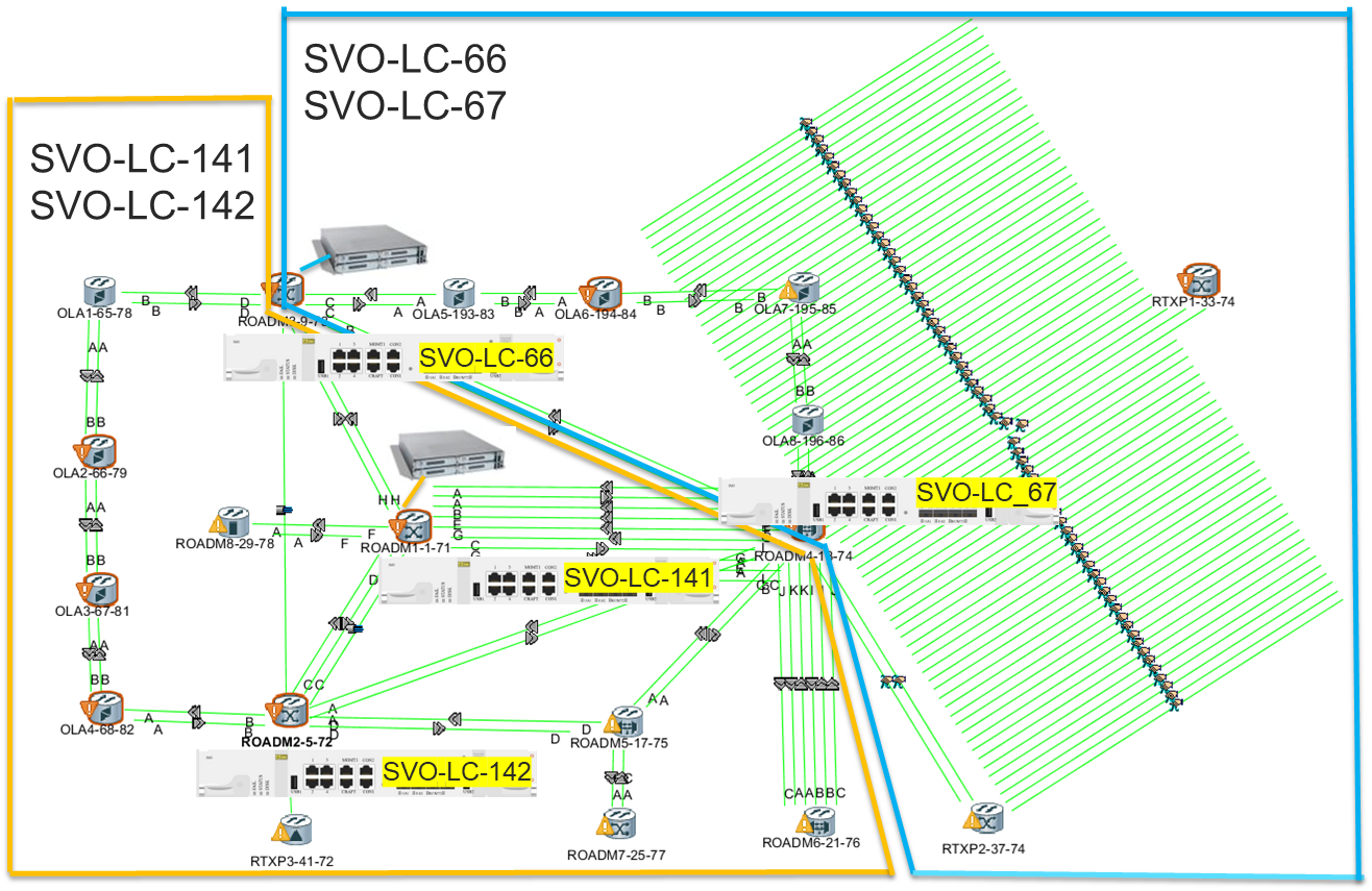
In our Golden Setup, there are two pairs of SVO card Geo HA located as follows:
-
Geo HA (UDC): SVO-LC-141 and SVO-LC-142 are installed on ROADM1 and ROADM2, respectively.
-
Geo HA (nearby-node): SVO card-66 and SVO card-67 are installed on ROADM3 and ROADM4, respectively.
| Cisco Optical Site Manager Instance Name | Cisco NCS 2000/NCS 1000 managed devices | Reserved Memory |
| ROADM1 (8-deg) | ROADM1-1-71 Kepler-45 | 4 GB |
| ROADM2 (4-deg) | ROADM2-5-72 RTXP3 | 2.1 GB |
| ROADM5 (3-deg) | ROADM5-17-75 | 2.1 GB |
| ROADM6 (3-deg) | ROADM6-21-76 | 2.1 GB |
| ROADM7 (1-deg) | ROADM7-25-77 | 2.1 GB |
| ROADM8 (1-deg) | ROADM8-29-78 | 2.1 GB |
| OLA1 | OLA1-64-78 | 2.1 GB |
| OLA2 | OLA2-65-79 | 2.1 GB |
| OLA3 | OLA3-66-80 | 2.1 GB |
| OLA4 | OLA4-67-81 | 2.1 GB |
| Cisco Optical Site Manager Instance Name | Cisco NCS 2000/NCS 1000 managed devices | Reserved Memory |
| ROADM3 (4-deg) | ROADM3-9-73 Kepler-49 | 2.1 GB |
| ROADM4 (12-deg) | ROADM4-13-74 RTXP1 RTXP2 | 4 GB |
| OLA5 | OLA5-193-82 | 2.1 GB |
| OLA6 | OLA6-194-83 | 2.1 GB |
| OLA6 | OLA6-195-84 | 2.1 GB |
| OLA8 | OLA8-196-85 | 2.1 GB |
Cisco Optical Site Manager instance
In an NCS 2000 network, a Cisco Optical Site Manager instance can manage multiple device types, including ROADM, OLA, Remote Transponder nodes, standalone transponders, and NCS 1000 transponders, as a single managed entity. With reference to the Golden Reference Setup (2.2), a single Cisco Optical Site Manager instance is used to manage multiple devices within a site.
These examples show how Cisco Optical Site Manager enables unified management of different device combinations within the same site:
-
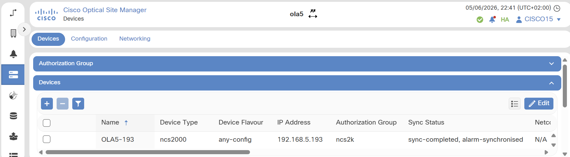
Cisco Optical Site Manager instance managing OLA nodes.
-
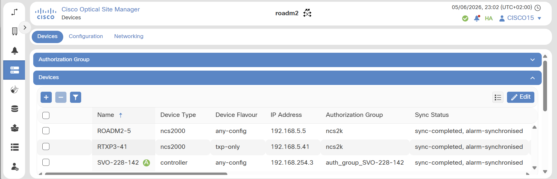
Cisco Optical Site Manager instance managing ROADM and remote transponder nodes.
-
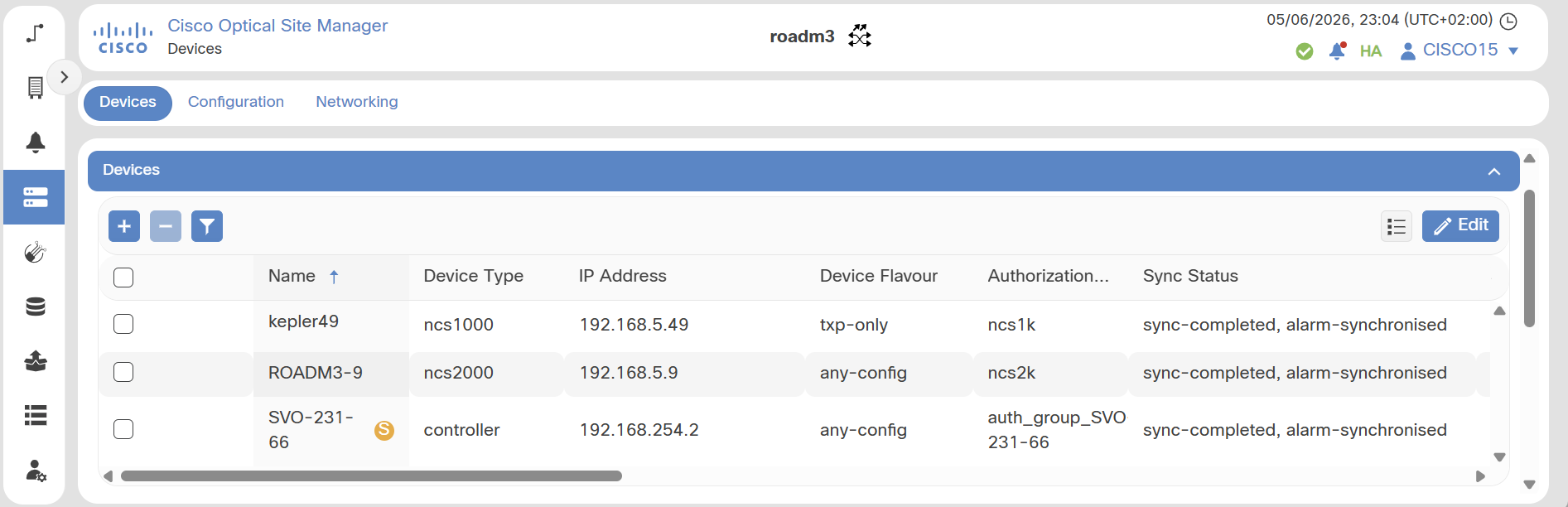
Cisco Optical Site Manager instance managing ROADM and one Cisco NCS 1014 device.
In this example, these Cisco Optical Site Manager instances are defined:
OLA5 Cisco Optical Site Manager instance
OLA5-193
ROADM2 Cisco Optical Site Manager instance
-
ROADM2-5-72
-
RTXP3-41-72
-
SVO-228-142 Controller (i.e. the SVO card plugged in ROADM2-5-72)
ROADM3 Cisco Optical Site Manager Instance
-
ROADM3-9-73
-
Kepler49
-
SVO-231-66 Controller (i.e. the SVO card plugged in ROADM3-9-73)
OLA
ROADM, remote transponder, and SVO card instance
ROADM, NCS 1000 transponder, and SVO card instance
UID mapping
The UID (Unique Identifier) uniquely identifies:
-
Each NCS 1000 or NCS 2000 chassis
-
Passive shelves
-
Passive modules placed directly in the rack.
UIDs are not reserved. In principle, any NCS 1000 chassis, NCS 2000 chassis, passive shelf, or passive module can be associated with any UID.
This ensures correct device management, synchronization, and configuration consistency within the network.
In release 26.x, the UID mapping is derived from the identifiers defined in the NCS 2000 system and visible in CTC, as shown in this table.
| NCS 2000/CTC | Cisco Optical Site Manager UID | |
| Chassis | NCS 2000 Chassis ID = N | Cisco Optical Site Manager Chassis UID = N |
| Passive Chassis | NCS 2000 Passive Chassis ID = N | Cisco Optical Site Manager Passive Chassis UID = 1000 + N |
| Passive Unit | NCS 2000 Passive Chassis ID = N | Cisco Optical Site Manager Passive Unit UID = 500 + N |
Before adding a new device (remote transponder or NCS 1000 Transponder), always verify the list of existing UIDs in the Cisco Optical Site Manager inventory to avoid overlaps.
-
When you add an NCS 1000 device, select the UID to associate with the NCS 1000 chassis. Use an identifier that is not already used in the ROADM. Otherwise, Cisco Optical Site Manager assigns the first available UID.
-
When you add an NCS 2000 remote TXP node or a simple transponder node, assign a first UID that is higher than the maximum chassis UID already present in the Cisco Optical Site Manager instance.
-
If a remote transponder has more than one chassis, Cisco Optical Site Manager will assign UIDs sequentially.
This figure shows ROADM2 and RTXP3 managed by the same Cisco Optical Site Manager instance.
You can force UID-to-NCS 2000 ID mapping by importing an XML file, as described in the device onboarding workflow.