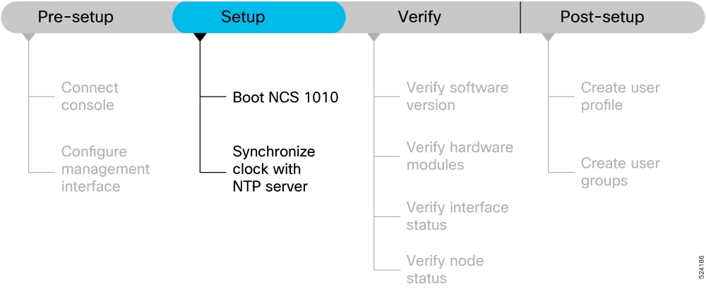
Provides the Cisco NCS 1010 setup workflow and related setup task sequence used to bring up the system for further configuration.
Complete these tasks to bring up your NCS 1010 for further configuration.
System Setup and Software Installation Guide for Cisco NCS 1010, IOS XR Releases
System Setup and Software Installation Guide for Cisco NCS 1010, IOS XR Releases
Provides the Cisco NCS 1010 setup workflow and related setup task sequence used to bring up the system for further configuration.
Complete these tasks to bring up your NCS 1010 for further configuration.
Use this procedure to boot Cisco NCS 1010.
Use the console port to connect to NCS 1010. By default, the console port connects to the XR mode. If necessary, you can establish subsequent connections through the management port, after it is configured.
| 1. | Connect a terminal to the console port of the RP. |
|
| 2. | Start the terminal emulation program on your workstation. The console settings are 9600 bps, 8 data bits, 1 stop bit and no parity. |
|
| 3. | Power on NCS 1010. To power on the shelves, install the AC or DC power supplies and cables. As NCS 1010 boots up, you can view the boot process details at the console of the terminal emulation program. |
|
| 4. | Press Enter. The boot process is complete when the system prompts you to enter the root-system username. If the prompt does not appear, wait for a while to give NCS 1010 more time to complete the initial boot procedure; then press Enter.
|
The boot Cisco NCS 1010 task is complete.
Use this supertask to prepare a bootable USB drive and boot Cisco NCS 1010 from that drive.
You need a USB drive with a storage capacity of at least 4 GB.
The USB drive should have a single partition.
NCS 1010 software image can be downloaded from Software Download page on Cisco.com.
Copy the compressed boot file from the software download page at Cisco.com to your local machine. The filename for the compressed boot file is in the format ncs1010-usb-boot-<release_number>.zip.
The bootable USB drive is used to reimage NCS 1010 for system upgrade or to boot the NCS 1010 in case of boot failure. A bootable USB drive is created by copying a compressed boot file into a USB drive. The USB drive becomes bootable after the contents of the compressed file are extracted.
You can complete this task using the Windows, Linux, or MAC operating systems available on your local machine. The exact operation to be performed for each generic step that is outlined here depends on the operating system in use.
Use this task to boot the NCS 1010 using the USB drive.
| 1. | Prepare a USB boot drive. |
|
| 2. | Start Cisco NCS 1010 from a USB drive. |
Cisco NCS 1010 boots from the USB image and reboots after installation.
Use this procedure to format the USB drive, copy the compressed boot file, verify the file, and extract the contents at the root of the drive.
You need a USB drive with a storage capacity of at least 4 GB.
The USB drive should have a single partition.
NCS 1010 software image can be downloaded from Software Download page on Cisco.com.
Copy the compressed boot file from the software download page at Cisco.com to your local machine. The filename for the compressed boot file is in the format ncs1010-usb-boot-<release_number>.zip.
The prepared USB drive contains the extracted boot files that make the drive bootable.
| 1. | Connect the USB drive to your local machine and format it with the FAT32 file system. |
|
| 2. | Copy the compressed boot file to the USB drive. |
|
| 3. | Verify that the copy operation is successful. To verify, compare the file size at source and destination. Also, verify the MD5 checksum value. |
|
| 4. | Extract the content of the compressed boot file by unzipping it in the USB drive. This makes the USB drive a bootable drive.
|
The USB drive is ready to boot Cisco NCS 1010.
Use this procedure to insert the prepared USB drive, select the BIOS boot option, and remove the drive after the image loads.
Prepare the USB boot drive before you start Cisco NCS 1010 from the drive. See Prepare a USB boot drive.
Use the console or BIOS boot option when you need to boot Cisco NCS 1010 from the prepared USB drive.
| 1. | Insert the USB drive in one of the USB ports of NCS 1010 line card/controller card. |
|
| 2. | Reboot NCS 1010 using power cycle or console.
|
|
| 3. | Press Esc to enter BIOS. |
|
| 4. | Select the Save & Exit tab of BIOS. 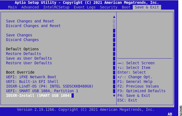
|
|
| 5. | Choose IOS -XR Install. The BIOS UI displays the USB drive vendor in the brackets, in this case, SMART USB 1084. The system detects USB and boots the image from USB. |
|
| 6. | Remove the USB drive after the
|
Cisco NCS 1010 starts from the USB drive and reboots after installation.
Use iPXE boot to reimage Cisco NCS 1010 through a network boot workflow.
Use iPXE boot when the router fails to boot or when no valid bootable partition is available. iPXE enables network boot for an offline router. The iPXE bootloader downloads and installs the ISO image located on an HTTP, FTP, or TFTP server and reimages the router.
iPXE boot can be invoked through the CLI terminal or through the BIOS interface.
Ensure that the DHCP server is set and running. For details, see Configure a DHCP server for iPXE boot.
Ensure that the management port of the NCS 1010 chassis is in UP state.
| 1. | Invoke iPXE boot through the CLI terminal. For details, see Boot Cisco NCS 1010 using iPXE from the CLI. |
|
| 2. | Invoke iPXE boot through the BIOS interface. For details, see Boot Cisco NCS 1010 using iPXE from BIOS. |
The iPXE boot process downloads the ISO image and reimages the Cisco NCS 1010 chassis.
Configure a DHCP server to provide Cisco NCS 1010 iPXE boot information.
A DHCP server must be configured for IPv4, IPv6, or both communication protocols before Cisco NCS 1010 can use iPXE boot.
For DHCPv6, send a routing advertisement (RA) message to all nodes in the network to indicate the method used to obtain the IPv6 address.
| 1. | If you use DHCPv6, configure Router Advertisement Daemon to allow the client to send the DHCP request. Example: |
|
| 2. | Create the dhcpd.conf file, dhcpv6.conf file, or both files in the /etc/ directory. The configuration file stores network information, such as the script path, ISO install file location, provisioning configuration file location, serial number, and chassis MAC address. |
|
| 3. | Add a host entry that uses the chassis MAC address. Example:Ensure that the DHCP host configuration is successful after the DHCP server is running. |
|
| 4. | If you identify the chassis by serial number, add a host entry that uses the chassis serial number. Example:Example:The chassis serial number is derived from the BIOS and is used as an identifier. |
The DHCP server provides the iPXE boot image or provisioning configuration file information to Cisco NCS 1010.
Invoke iPXE boot from the CLI terminal to reimage the chassis.
Use this method to start the iPXE boot process from the CLI terminal.
Ensure that the DHCP server is set and running.
Ensure that the management port of the NCS 1010 chassis is in UP state.
| 1. | Run the command to invoke the iPXE boot process and reimage the chassis. reload bootmedia network location all Example: |
|
| 2. | Review the iPXE boot output. Example:
The iPXE boot process downloads the ISO image and displays the user access verification prompt.
|
Cisco NCS 1010 boots through iPXE from the CLI terminal and starts the reimage workflow.
Invoke iPXE boot from the BIOS interface to reimage the chassis.
Use this method to start the iPXE boot process from the BIOS interface.
Ensure that the DHCP server is set and running.
Ensure that the management port of the NCS 1010 chassis is in UP state.
| 1. | Reboot NCS 1010 using power cycle or console. |
|
| 2. | Press Esc to enter BIOS. |
|
| 3. | Select the Save & Exit tab of BIOS. |
|
| 4. | Choose UEFI: iPXE Network Boot. Example:
The iPXE boot process downloads the ISO image and displays the user access verification prompt.
|
Cisco NCS 1010 boots through iPXE from the BIOS interface and starts the reimage workflow.
Install a new image without using the Golden ISO feature.
Before the introduction of Golden ISO, you had to perform this sequence to install a new image.
Ensure that the mini ISO is available.
Ensure that all relevant SMUs, optional packages, and IOS XR configuration are available.
| 1. | Boot the system with mini ISO. You can use iPXE or USB boot. |
|
| 2. | Install, add, and activate all relevant SMUs and optional packages on NCS 1010.
NCS 1010 reloads when any SMU reloads.
|
|
| 3. | Apply IOS XR configuration. |
The new image is installed without using Golden ISO.
Build a customized Golden ISO image that includes the mini ISO, required SMUs, and IOS XR configuration.
Golden ISO is a feature that enables you to build a customized ISO using mini ISO, required SMUs, and IOS XR configuration.
Golden ISO saves installation effort and time. It makes the system available in a single command and boot.
The gisobuild.py script is available at /pkg/bin/gisobuild.py.
Install operation over IPv6 is not supported.
Copy the /pkg/bin/gisobuild.py script from NCS 1010 to the Linux environment.
Ensure that the mini ISO, required SMUs, and IOS XR configuration file are available.
| 1. | Build the Golden ISO image.
gisobuild.py -i mini-iso -r rpm-directory -c xr-config -l label
Example: |
|
| 2. | Review the Golden ISO build output. Example:
The command output shows that Golden ISO creation succeeded and displays the Golden ISO image location.
|
|
| 3. | Verify the Golden ISO file format. Use these Golden ISO filename formats:
Example:Example 1: ncs1010-golden-x-7.0.1.014I-V1.iso Example 2: ncs1010-goldenk9-x-7.0.1.014I-V1.iso |
The Golden ISO boot image is built and its filename format is verified.
A Network Time Protocol implementation is a time synchronization function that
uses UDP and Coordinated Universal Time to synchronize device clocks,
forms configured associations with NTP servers to exchange timing messages, and
supports accurate event timing for network management, security, planning, and debugging.
| Feature Name |
Release Information |
Feature Description |
|---|---|---|
| NTP Support |
|
Network Time Protocol (NTP) allows devices to synchronize clocks with the NTP servers, maintaining the most accurate time. NCS 1010 now supports time synchronization. In modern and large networks, time synchronization is critical because every aspect of managing, securing, planning, and debugging a network depends on the time of occurrence of events. Commands added:
|
NTP uses the User Datagram Protocol (UDP) as its transport protocol. All NTP communication uses Coordinated Universal Time (UTC). An NTP network usually receives its time from an authoritative time source, such as a radio clock or an atomic clock attached to a time server. NTP distributes this time across the network.
NTP uses the concept of a "stratum" to describe how many NTP hops away a machine is from an authoritative time source. A "stratum 1" time server typically has an authoritative time source (such as a radio or atomic clock, or a GPS time source) directly attached, a "stratum 2" time server receives its time through NTP from a "stratum 1" time server, and so on.
The communications between machines running NTP (known as associations) are usually statically configured; each machine is given the IP address of all machines with which it should form associations. Accurate timekeeping is made possible by exchanging NTP messages between each pair of machines with an association.
An NTP broadcast client listens for broadcast messages sent by an NTP broadcast server at a designated IPv4 address. The client synchronizes the local clock using the first received broadcast message.
Use this procedure to synchronize the clock with an NTP server.
There is an independent system clock for IOS XR. To ensure that this clock does not deviate from true time, it must be synchronized with the clock of an NTP server.
| 1. | Enter configuration mode. configure Example:Enters the configuration mode. |
|
| 2. | Enter NTP configuration mode. ntp Example:Enters NTP configuration mode. |
|
| 3. | Configure an NTP server. server 198.51.100.1 version 4 prefer iburst server 2001:DB8::1 version 4 prefer iburst Example:Synchronizes the console clock with the specified NTP server.
|
|
| 4. | Save or exit the configuration session. end commit
Example:or Saves configuration changes.
|
|
| 5. | Verify the running NTP configuration. show running-config ntp Example:Displays the running configuration. |
The synchronize the clock with an NTP server task is complete.
Use this procedure to verify NTP synchronization status.
This task explains how to verify the status of NTP components.
| 1. | Verify NTP associations. show ntp associations Example:selected, + candidate, - outlayer, x falseticker, ~ configured Displays the status of NTP associations. |
|
| 2. | Verify detailed NTP association information. show ntp associations detail Example: |
|
| 3. | Verify detailed NTP association information for a location. show ntp associations detail location 0/RP0/CPU0 Example: |
|
| 4. | Verify NTP status. show ntp status Example:
Verifies that the clock is synchronized with the NTP server.
|
The verify NTP synchronization status task is complete.
For details about NTP issue resolution, see Troubleshoot Network Time Protocol Issues.