This topic describes the OTDR line card, its physical and logical ports, supported measurement modes, and operating limits for Cisco NCS 1001 fiber inspection.
The Optical Time Domain Reflectometer (OTDR) is a Cisco NCS 1001 line card that measures optical fiber characteristics between optical nodes.
The line card contains two bidirectional OTDRs and two filters that combine C-band, optical supervisory channel (OSC), and OTDR signals. Each internal OTDR can measure both transmit (TX) and receive (RX) fibers by using an internal optical switch.
The OTDR line card connects to the OSC port on the optical amplifier. Measurement data is stored in an .SOR file and can be exported from Cisco NCS 1001 by using SCP, TFTP, or SFTP.
The OTDR line card:
provides information about insertion loss and reflection points on the optical fiber,
inspects the transmission fiber,
identifies discontinuities or defects on the fiber,
measures the distance and magnitude of insertion loss and reflection loss events, and
improves scan performance through scan parameters that match the fiber plant, such as span length, reflection contribution, and major events.
OTDR card front view
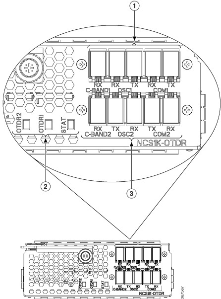
Callout |
Description |
|---|---|
1 |
OTDR1 interface |
2 |
LED status |
3 |
OTDR2 interface |
Logical ports
The OTDR card associates physical ports with these logical OTS controller ports.
OTDR port |
Logical port |
|---|---|
C-Band-1 RX |
controller OTS 0/slot/0/0 |
COM1 (RX, TX) |
controller OTS 0/slot/0/1 |
OSC1 (RX, TX) |
controller OTS 0/slot/0/2 |
C-Band-2 RX |
controller OTS 0/slot/0/3 |
COM2 (RX, TX) |
controller OTS 0/slot/0/4 |
OSC2 (RX, TX) |
controller OTS 0/slot/0/5 |
For command output that displays these logical ports and photodiode power levels, see view the logical ports and photodiode power levels.
OTDR modes
OTDR supports automatic and expert modes.
Mode |
Description |
|---|---|
Automatic |
Uses automated training and measurement phases. Training measures optical return loss (ORL) and prepares the internal OTDR measurement parameters before the measurement starts. |
Expert |
Requires the user to configure the OTDR scan parameters. The mode does not run a training phase and does not automatically adjust the scan parameters. |
OTDR limitations
When Cisco NCS 1001 uses the OTDR line card, the OSC channel uses 1610 nm and OTDR uses 1518 nm.
OTDR supports up to 20 dB span loss or 100 km fiber length.
Do not start OTDR measurements simultaneously from two different nodes because the results and graph are not valid.
OTDR measurement during an OTDR-HIGH-REFLECTION alarm, with reflections approximately greater than -25 dB, can provide low event accuracy.
OTDR graphs can be truncated for fiber spools from 1.00 km to 1.05 km, 25.0 km to 25.6 km, or 80.0 km to 83.9 km.
OTDR supports up to -14 dB reflection. The OTDR-HIGH-REFLECTION alarm is raised when R(dB) - 2*NL(dB) is greater than -20 dB, where R is reflectivity and NL is loss.
LOS-P alarm handling
When an EDFA module is connected to the OTDR module without an OSC channel between them, an LOS-P alarm is raised on OTS 0/x/0/2 of the EDFA module. Configure the OTS controller under maintenance or shut down the EDFA receive direction on port 0/x/0/2 to suppress the alarm and resume normal OTDR operation.
Example: Configure the OTS controller under maintenance.
RP/0/RP0/CPU0:ios#configure
RP/0/RP0/CPU0:ios(config)#controller ots 0/3/0/2
RP/0/RP0/CPU0:ios(config-ots)#sec-admin-state maintenance
RP/0/RP0/CPU0:ios(config-ots)#commit
Example: Shut down the EDFA port in the receive direction.
RP/0/RP0/CPU0:ios#configure
RP/0/RP0/CPU0:ios(config)#controller ots 0/3/0/2
RP/0/RP0/CPU0:ios(config-ots)#rx-enable 0
RP/0/RP0/CPU0:ios(config-ots)#commit