Important. Results generated by AI. Before using results, verify accuracy and completeness.
Copy
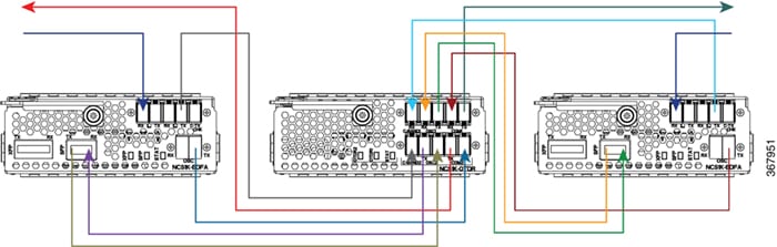
Use this procedure to connect a single OTDR card to the EDFA cards in an ILA node so both ILA directions support OTDR measurements.
Connect OTDR port 1 to the EDFA in slot 1 and OTDR port 2 to the EDFA in slot 3.
In an Intermediate Line Amplifier (ILA) node, one OTDR card supports both ILA directions. Two EDFA cards and one OTDR line card are installed in the same Cisco NCS 1001 system.
Procedure
1.
Cable OTDR port 1 to the EDFA in slot 1.
Connect an LC/LC fiber from OTDR port 1 COM TX to the fiber span Line TX that faces EDFA slot 1.
Connect an LC/LC fiber from EDFA slot 1 COM TX to C-band 1 RX.
Connect an LC/LC fiber from OTDR OSC TX port 1 to the OSC pluggable RX port inserted into EDFA slot 1.
Connect an LC/LC fiber from the OSC pluggable TX port inserted into EDFA slot 1 to OTDR OSC RX port 1.
Connect an LC/LC fiber from EDFA slot 1 OSC TX to OTDR COM RX port 1.
2.
Cable OTDR port 2 to the EDFA in slot 3.
Connect an LC/LC fiber from OTDR port 2 COM TX to the fiber span Line TX that faces EDFA slot 3.
Connect an LC/LC fiber from EDFA slot 3 COM TX to C-band 2 RX.
Connect an LC/LC fiber from OTDR OSC TX port 2 to the OSC pluggable RX port inserted into EDFA slot 3.
Connect an LC/LC fiber from the OSC pluggable TX port inserted into EDFA slot 3 to OTDR OSC RX port 2.
Connect an LC/LC fiber from EDFA slot 3 OSC TX to OTDR COM RX port 2.
Figure 1. Cabling for ILA configuration
The OTDR card is connected to both ILA directions.