Configuration Guide for Cisco NCS 1001, IOS XR Release 25.x.x

PDF

Configuration Guide for Cisco NCS 1001, IOS XR Release 25.x.x

Optical amplifier module

Want to summarize with AI?

Log in

Describes the NCS1K-EDFA optical amplifier module, including preamplifier and booster functions, OSC support, OCM monitoring, front-panel callouts, controller-to-port mappings, and COM-CHECK safety behavior.


The optical amplifier module (NCS1K-EDFA) is an NCS 1001 optical module that provides preamplifier and booster amplification for line-system deployments.

  • Preamplifier (LINE-RX to COM-TX): Provides a single preamplifier variant with switchable gain ranges according to link loss.

    • Range 1 provides 0 to 24 dB gain, and tilt control provides 24 to 27 dB gain with uncontrolled tilt.

    • Range 2 provides 20 to 34 dB gain, and tilt control provides 34 to 37 dB gain with uncontrolled tilt.

    • The COM-TX port provides 23 dBm output power.

  • Booster amplifier (COM-RX to LINE-TX): Provides true variable gain booster amplification.

    • The booster amplifier supports gain range 1 to 20. Gain range 20 to 25 has uncontrolled tilt.

    • The LINE-TX port provides 23 dBm output power.

  • The add or drop OSC channel supports both 1510 nm and 1610 nm wavelengths with a tolerance of +/-10 nm.

  • The OCM assesses channel presence, gain regulation, and per-channel power monitoring.

Feature history

Table 1. Feature history

Feature name

Release information

Feature description

Amplifier behavior

Cisco IOS XR Release 7.3.1

Grid mode configuration for the optical amplifier supports 75GHz spaced channels.

You can optimize the optical spectrum and granularity using gridless configuration. You can provision channels with arbitrary channel frequencies and channel widths. Up to 96 channels can be configured using gridless configuration.

Modified commands include:

  • hw-module

  • show controllers

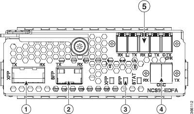
EDFA front view

Figure 1. EDFA front view

EDFA front view

Table 2. EDFA front view callouts

1

XFP for OSC and additional OTDR feature

2

SFP for OSC (Optical Service Channel)

3

Status LED

4

Service channel input and output ports [OSC – RX, TX]

5

PRE and BST amplifier input and output ports

[L (LINE) – RX, TX]

[C (COM) – RX, TX]

[COM – CHECK]

Controller and optical port mappings

This table describes the mapping of controllers and optical ports for the optical amplifier module.

Table 3. Controller and optical port mappings

Controller

Optical ports

Ots 0/slot/0/0

  • COM-RX (booster input)

  • COM-TX (preamplifier output)

Ots 0/slot/0/1

  • LINE-RX (preamplifier input)

  • LINE-TX (booster output)

Ots 0/slot/0/2

  • OSC-RX

  • OSC-TX

Ots 0/slot/0/3

COM-CHECK

COM-CHECK configuration

The COM-CHECK configuration supports safety behavior for high-power preamplifier deployments.

  • Safety measures protect the fiber intranode between the preamplifier and the mux or demux section when the total output power on the COM-TX port is up to 23 dB. These measures compensate for extremely long spans.

  • If the output power on COM-TX is less than or equal to 20 dB, the COM-CHECK port can be turned off and does not require a physical connection between the pre COM-CHECK and demux monitor port.

  • In some cases, such as spans with high power requirements, safety on the preamplifier is necessary.

  • The COM-CHECK PD9 is the safety port.

  • The COM-RX controller, such as Ots 0/s/0/0, is not part of safety.

  • The safety restart process is similar to the booster case, with some difference in the APR Check phase.
Amplifier configuration

NCS 1001 supports manual and automatic methods to control optical amplifier settings.

NCS 1001 supports two methods to control amplifiers:

  • Manual—the user controls all the amplifier settings.

  • Automatic—the internal amplifier power regulator controls all the amplifier settings.

UDC port configuration

UDC port configuration uses these slot associations and traffic-handling rules.

  • There are three UDC RJ-45 ports on the faceplate of NCS 1001. UDC1 is associated with slot 1, UDC2 is associated with slot 2, and UDC3 is associated with slot 3.

  • UDC ports are Gigabit Ethernet ports that carry any Ethernet traffic.

  • UDC traffic is added and dropped through OSC filters in the NCS1K-EDFA optical amplifier module.

  • NCS 1001 tags and untags UDC traffic based on the configured UDC VLAN.

  • The system supports tagged, multiple-tagged, and untagged traffic.

  • Full utilization is not available, because four bytes of tag data are added to each packet.

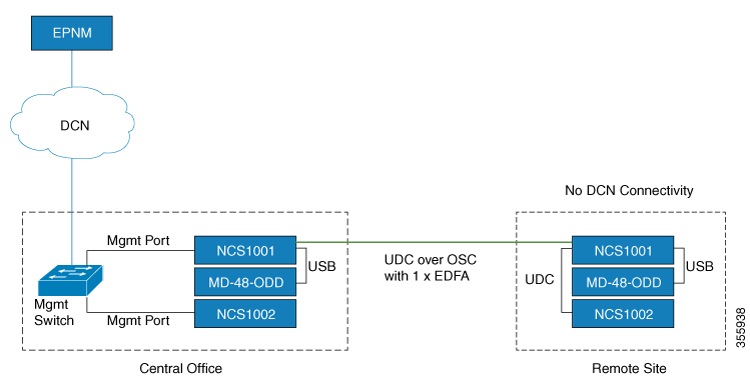
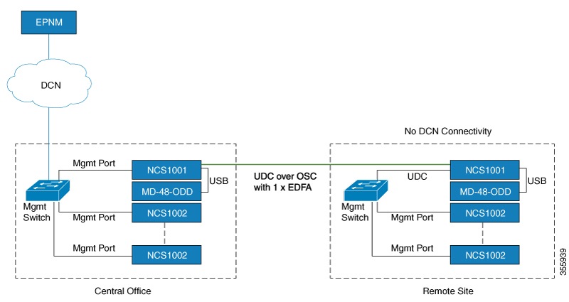
These diagrams describe the application of UDC that can be used by EPNM to manage NCS 1000 series at the remote site.

Figure 2. UDC application for remote management - scenario one
UDC application for remote management
Figure 3. UDC application for remote management - scenario two
UDC application for remote management

Configure an amplifier module

Configure the amplifier module slot, node type, grid mode, and UDC VLAN settings.

For details about amplifier module configuration parameters, see Amplifier module configuration parameters.

Procedure

Use this command to configure the amplifier module.

hw-module location 0/RP0/CPU0 slot slot-number ampli node-type value grid-mode value udc-vlan value

Example:

In this sample, the amplifier module is inserted in slot 3 and udc-vlan is set to 4000.


configure
      hw-module location 0/RP0/CPU0 slot 3 ampli
         [
             grid-mode 100GHz
             udc-vlan 4000
         ]
commit
end

The configuration is committed and the optical module uses the requested settings.


Amplifier module configuration parameters

Use this reference to choose values for the amplifier module configuration command.

This table provides information about the supported configuration parameters for the amplifier module.

Table 4. Amplifier module configuration parameters

Parameter

Description

Range or values

Default

grid-mode

Defines the optical spectrum on the interfaces of the amplifier module.

  • 100 GHz—Configures the amplifier with 100GHz grid channels and 48-channel spacing.

  • 50 GHz—Configures the amplifier with 50GHz grid channels and 96-channel spacing.

  • 75 GHz—Configures the amplifier with 75GHz grid channels and 64-channel spacing.

    Note

    The NCS1K-MD-64-C optical passive multiplexer and demultiplexer module, introduced in Release 7.3.1, allows you to configure the amplifier with 75GHz grid channels.

  • gridless—Configures the amplifier in flex spectrum mode.

50GHz

node-type

Defines the type of node in which the amplifier operates.

TERM, ILA

TERM

udc-vlan

Defines the VLAN associated with the selected slot and its UDC port.

2 to 4080


Configure flex channels on the amplifier module

You can optimize the optical spectrum and granularity using the gridless configuration. In gridless configuration, the fixed ITU-T grid that defines specific channel frequencies and channel widths is not considered. You can provision channels with arbitrary channel frequencies and channel widths. You can configure up to 96 channels using the gridless configuration.

Table 5. Flex channel configuration parameters

Parameter

Description

Range

flex-chan-id

Defines the channel identifier.

1 to 96

chan-central-freq

Defines the central frequency of the channel.

191350 to 196100 in multiples of 125

chan-width

Defines the width of the channel.

500 (50.0 GHz) to 8000 (800.0 GHz) in multiples of 12.5 GHz

Procedure

1.

Use these commands to configure flex channels on the amplifier module.

Example:


configure
hw-module location 0/RP0/CPU0 slot 2 ampli flex-mode
hw-module location 0/RP0/CPU0 slot 2 ampli grid-mode gridless
hw-module location 0/RP0/CPU0 slot 2 ampli flex-channel-id 5 chan-central-freq 1931750 chan-width 6500
commit
end
2.

Use the show controllers ots-och summary command to verify the configured flex channel summary.

Example:

show controllers ots-och 0/2/0/0/5 summary
3.

Use the show controllers ots-och command to verify the configured flex channel details.

Example:

show controllers ots-och 0/2/0/0/5

The configuration is committed and the optical module uses the requested settings.

In this sample, the amplifier module is configured in flex spectrum.


configure
      hw-module location 0/RP0/CPU0 slot 2 ampli flex-mode
      hw-module location 0/RP0/CPU0 slot 2 ampli grid-mode gridless
      hw-module location 0/RP0/CPU0 slot 2 ampli flex-channel-id 5 
      chan-central-freq 1931750 chan-width 6500
commit
end

This sample shows the configured channel with its frequency and width.

RP/0/RP0/CPU0#show controllers ots-och 0/2/0/0/5 summary

Fri Oct  9 10:43:44.002 CEST
       Port       	Type   Status   TX Power   RX Power   
                                  	  (dBm)      (dBm)    
      ----------------- -----   -------   ---------  ---------
      Ots-Och0_2_0_0_5    Com     N/A     -8.60       -8.90      
      TX psd     RX psd         Central         Channel Width
      (nW/MHz)   (nW/MHz)       Frequency(GHz)    (GHz)
      ---------  ------------   -------------    --------------   
        0.410       0.450         193175.0         650.0

RP/0/RP0/CPU0#show controllers ots-och 0/2/0/0/5


Fri Oct  9 10:46:33.046 CEST

 Controller State: Up

 Transport Admin State: Maintenance

 Port Type: Com

 Laser State: Unknown

 Optics Status::


         Alarm Status:
         -------------
         Detected Alarms: None


         Alarm Statistics:
         -----------------
         LOW-RX-PWR = 0
         LOW-TX-PWR = 0
         RX-LOS-P = 0
         RX-LOC = 0
         AMPLI-GAIN-DEG-LOW = 0
         AMPLI-GAIN-DEG-HIGH = 0
         AUTO-LASER-SHUT = 0
         AUTO-POW-RED = 0
         AUTO-AMPLI-CTRL-DISABLED = 0
         AUTO-AMPLI-CFG-MISMATCH = 0
         SWITCH-TO-PROTECT = 0
         AUTO-AMPLI-CTRL-RUNNING = 0

         Parameter Statistics:
         ---------------------
         TX Power = -8.60 dBm
         RX Power = -8.90 dBm
         TX psd = 0.440 nW/MHz
         RX psd = 0.450 nW/MHz
         Channel Central Frequency = 193175.0 GHz
         Channel Width = 650.0 GHz

         Configured Parameters:
         ------------------------
         Rx Low Threshold = -25.0 dBm
         Tx Low Threshold = -25.0 dBm

Modify central frequency and channel width on the amplifier module

You can change the central frequency, channel width, or both for a configured channel ID. The channel ID cannot be arbitrarily changed before unconfiguring the channel.

Procedure

1.

Change the central frequency of the configured channel.

Example:

hw-module location 0/RP0/CPU0 slot 1 ampli flex-channel-id 24 
          chan-central-freq 1949000 chan-width 500
2.

Change the channel width of the same channel.

Example:

hw-module location 0/RP0/CPU0 slot 1 ampli flex-channel-id 24 
          chan-central-freq 1949000 chan-width 1500
3.

Change both the central frequency and channel width of the channel.

Example:

hw-module location 0/RP0/CPU0 slot 1 ampli flex-channel-id 24 
          chan-central-freq 1932625 chan-width 6125

The configuration is committed and the optical module uses the requested settings.