Configuration Guide for Cisco NCS 1001, IOS XR Release 25.x.x

PDF

Configuration Guide for Cisco NCS 1001, IOS XR Release 25.x.x

OTDR measurement in automatic mode based on events

Want to summarize with AI?

Log in

This topic explains which events start OTDR automatic scans and how the supported deployment scenarios determine the autoscan configuration for node pairs.


OTDR automatic measurement can start on both TX and RX directions between two nodes when specific network events occur.

  • An automatic scan starts when a loss of signal (LOS) alarm is raised or cleared on the line port of an EDFA, such as controller OTS 0/x/0/1. If an automatic scan is already running, a new LOS state change aborts the current scan and starts a new one.

  • An automatic scan also starts when the difference between the current span-loss value and the previous span-loss sample exceeds the configured span-loss delta value.

    hw-module location 0/RP0/CPU0 slot <n> ampli span-loss span-loss-delta 20

Supported deployment scenarios

OTDR modules can be deployed in four different scenarios:

  • Node A connects to Node B, and each node has its own OTDR module.

  • Node A connects to Node B, and a single OTDR module is installed in either Node A or Node B.

  • Node A connects to Node B, and a single OTDR module is installed in a different Node C.

  • Node A connects to Node B, and OTDR modules are installed in different Nodes C and D.

Note

Nodes A and B can be terminal nodes or ILA nodes.

Configure OTDR autoscan for scenario 1

Configure the remote node and OTDR autoscan commands for the selected event-based automatic scan scenario.

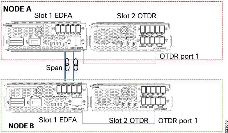
In scenario 1, OTDR modules are installed in both nodes. Each OTDR connects to its local EDFA, and both EDFAs face the same fiber span.

Figure 1. Scenario 1 EDFA remote node configuration

Procedure

1.

Configure the remote node feature for each EDFA module on Node A and Node B.

Example:


Node A:
hw-module location 0/RP0/CPU0 slot 1 ampli remote-node local-ipv4 <IP Node A> remote-ipv4 <IP Node B> remote-slot-id 1

Node B:
hw-module location 0/RP0/CPU0 slot 1 ampli remote-node local-ipv4 <IP Node B> remote-ipv4 <IP Node A> remote-slot-id 1
2.

Configure OTDR autoscan for each EDFA module on Node A and Node B.

Example:

Node A:
hw-module location 0/RP0/CPU0 slot 1 ampli otdr-autoscan otdr-module-ipv4-addr <IP Node A> otdr-slot-id 2 otdr-port-id 1 ampli-far-end-ipv4-addr <IP Node B> ampli-far-end-slot-id 1 scan-type AUTO

Node B:
hw-module location 0/RP0/CPU0 slot 1 ampli otdr-autoscan otdr-module-ipv4-addr <IP Node B> otdr-slot-id 2 otdr-port-id 1 ampli-far-end-ipv4-addr <IP Node A> ampli-far-end-slot-id 1 scan-type AUTO
3.

Configure the remote node OTDR autoscan for each OTDR module on Node A and Node B.

Example:

Node A:
hw-module location 0/RP0/CPU0 slot 2 otdr port 1 otdr-autoscan otdr-module-ipv4-addr <IP Node A> ampli-far-end-ipv4-addr <IP Node A> ampli-far-end-slot-id 1 scan-type AUTO

Node B:
hw-module location 0/RP0/CPU0 slot 2 otdr port 1 otdr-autoscan otdr-module-ipv4-addr <IP Node B> ampli-far-end-ipv4-addr <IP Node B> ampli-far-end-slot-id 1 scan-type AUTO

The event-based OTDR automatic scan configuration is ready for the selected scenario.


Configure OTDR autoscan for scenario 2

Configure the remote node and OTDR autoscan commands for the selected event-based automatic scan scenario.

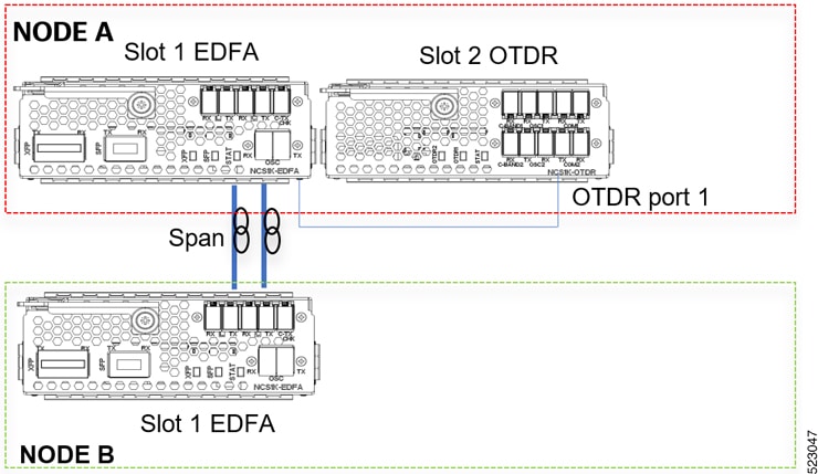
In scenario 2, one OTDR module is installed in Node A or Node B. The OTDR connects to only one EDFA that faces the fiber span.

Figure 2. Scenario 2 EDFA remote node configuration

Procedure

1.

Configure the remote node feature for each EDFA module on Node A and Node B.

Example:

Node A:
hw-module location 0/RP0/CPU0 slot 1 ampli remote-node local-ipv4 <IP Node A> remote-ipv4 <IP Node B> remote-slot-id 1

Node B:
hw-module location 0/RP0/CPU0 slot 1 ampli remote-node local-ipv4 <IP Node B> remote-ipv4 <IP Node A> remote-slot-id 1
2.

Configure OTDR autoscanfor the EDFA connected to the single OTDR module in the same node.

Example:

Node A:
hw-module location 0/RP0/CPU0 slot 1 ampli otdr-autoscan otdr-module-ipv4-addr <IP Node A> otdr-slot-id 2 otdr-port-id 1 ampli-far-end-ipv4-addr <IP Node A> ampli-far-end-slot-id 1 scan-type AUTO
3.

Configure OTDR autoscan on the single OTDR module.

Example:

Node A:
hw-module location 0/RP0/CPU0 slot 2 otdr port 1 otdr-autoscan otdr-module-ipv4-addr <IP Node A> ampli-far-end-ipv4-addr <IP Node A> ampli-far-end-slot-id 1 scan-type AUTO
Note

Both the EDFA and OTDR configurations share the same IP address as there is only one OTDR module connected to single EDFA in the same node.

The event-based OTDR automatic scan configuration is ready for the selected scenario.


Configure OTDR autoscan for scenario 3

Configure the remote node and OTDR autoscan commands for the selected event-based automatic scan scenario.

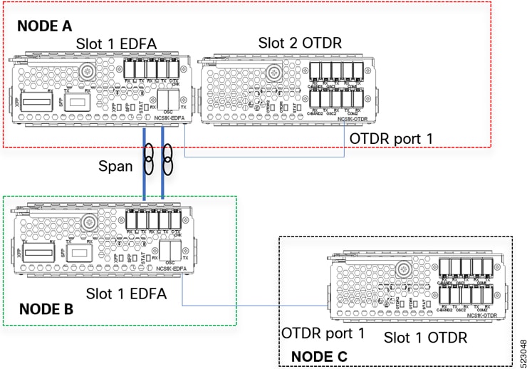
In scenario 3, a single OTDR module is installed in Node C and connects to the EDFA in Node B.

Figure 3. Scenario 3 EDFA remote node configuration

Procedure

1.

Configure the remote node feature for each EDFA module on Node A and Node B.

Example:


Node A:
hw-module location 0/RP0/CPU0 slot 1 ampli remote-node local-ipv4 <IP Node A> remote-ipv4 <IP Node B> remote-slot-id 1

Node B:
hw-module location 0/RP0/CPU0 slot 1 ampli remote-node local-ipv4 <IP Node B> remote-ipv4 <IP Node A> remote-slot-id 1
2.

Configure OTDR autoscan for each EDFA module on Node A and Node B.

Example:

Node A:
hw-module location 0/RP0/CPU0 slot 1 ampli otdr-autoscan otdr-module-ipv4-addr <IP Node A> otdr-slot-id 2 otdr-port-id 12 ampli-far-end-ipv4-addr <IP Node B> ampli-far-end-slot-id 1 scan-type AUTO

Node B:
hw-module location 0/RP0/CPU0 slot 1 ampli otdr-autoscan otdr-module-ipv4-addr <IP Node C> otdr-slot-id 1 otdr-port-id 12 ampli-far-end-ipv4-addr <IP Node A> ampli-far-end-slot-id 1 scan-type AUTO
3.

Configure OTDR autoscan for each OTDR module on Node A and Node C.

Example:

Node A:
hw-module location 0/RP0/CPU0 slot 2 otdr port 1 otdr-autoscan otdr-module-ipv4-addr <IP Node A> ampli-far-end-ipv4-addr <IP Node A> ampli-far-end-slot-id 1 scan-type AUTO

Node C:
hw-module location 0/RP0/CPU0 slot 1 otdr port 1 otdr-autoscan otdr-module-ipv4-addr <IP Node C> ampli-far-end-ipv4-addr <IP Node B> ampli-far-end-slot-id 1 scan-type AUTO

The event-based OTDR automatic scan configuration is ready for the selected scenario.


Configure OTDR autoscan for scenario 4

Configure the remote node and OTDR autoscan commands for the selected event-based automatic scan scenario.

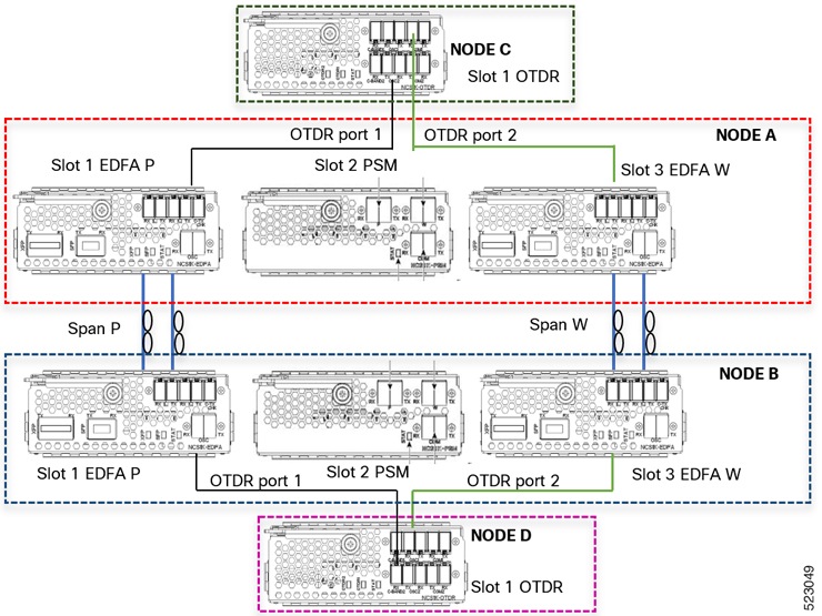
In scenario 4, OTDR modules are installed in Nodes C and D. Each OTDR node connects to its section-protection EDFA node.

Figure 4. Scenario 4 EDFA remote node configuration

Procedure

1.

Configure the EDFA remote node feature for each EDFA module on Node A and Node B.

Example:

Node A:
hw-module location 0/RP0/CPU0 slot 1 ampli remote-node local-ipv4 <IP Node A> remote-ipv4 <IP Node B> remote-slot-id 1
hw-module location 0/RP0/CPU0 slot 3 ampli remote-node local-ipv4 <IP Node A> remote-ipv4 <IP Node B> remote-slot-id 3

Node B:
hw-module location 0/RP0/CPU0 slot 1 ampli remote-node local-ipv4 <IP Node B> remote-ipv4 <IP Node A> remote-slot-id 1
hw-module location 0/RP0/CPU0 slot 3 ampli remote-node local-ipv4 <IP Node B> remote-ipv4 <IP Node A> remote-slot-id 3
2.

Configure OTDR autoscan for each EDFA module on Node A and Node B.

Example:

Node A:
hw-module location 0/RP0/CPU0 slot 1 ampli otdr-autoscan otdr-module-ipv4-addr <IP Node C> otdr-slot-id 1 otdr-port-id 1 ampli-far-end-ipv4-addr <IP Node B> ampli-far-end-slot-id 1 scan-type AUTO
hw-module location 0/RP0/CPU0 slot 3 ampli otdr-autoscan otdr-module-ipv4-addr <IP Node C> otdr-slot-id 1 otdr-port-id 2 ampli-far-end-ipv4-addr <IP Node B> ampli-far-end-slot-id 3 scan-type AUTO

Node B:
hw-module location 0/RP0/CPU0 slot 1 ampli otdr-autoscan otdr-module-ipv4-addr <IP Node D> otdr-slot-id 1 otdr-port-id 1 ampli-far-end-ipv4-addr <IP Node A> ampli-far-end-slot-id 1 scan-type AUTO
hw-module location 0/RP0/CPU0 slot 3 ampli otdr-autoscan otdr-module-ipv4-addr <IP Node D> otdr-slot-id 1 otdr-port-id 2 ampli-far-end-ipv4-addr <IP Node A> ampli-far-end-slot-id 3 scan-type AUTO
3.

Configure OTDR autoscan for each OTDR module on Node C and Node D.

Example:

Node C:
hw-module location 0/RP0/CPU0 slot 1 otdr port 1 otdr-autoscan otdr-module-ipv4-addr <IP Node C> ampli-far-end-ipv4-addr <IP Node A> ampli-far-end-slot-id 1 scan-type AUTO
hw-module location 0/RP0/CPU0 slot 1 otdr port 2 otdr-autoscan otdr-module-ipv4-addr <IP Node C> ampli-far-end-ipv4-addr <IP Node A> ampli-far-end-slot-id 3 scan-type AUTO

Node D:
hw-module location 0/RP0/CPU0 slot 1 otdr port 1 otdr-autoscan otdr-module-ipv4-addr <IP Node D> ampli-far-end-ipv4-addr <IP Node B> ampli-far-end-slot-id 1 scan-type AUTO
hw-module location 0/RP0/CPU0 slot 1 otdr port 2 otdr-autoscan otdr-module-ipv4-addr <IP Node D> ampli-far-end-ipv4-addr <IP Node B> ampli-far-end-slot-id 3 scan-type AUTO

The event-based OTDR automatic scan configuration is ready for the selected scenario.


Configure OTDR in automatic mode based on events

Configure the EDFA module and OTDR module autoscan parameters on both the near-end and far-end nodes.

The sample assumes that both the EDFA and OTDR modules are present on the same node.

Procedure

1.

Configure the EDFA module for OTDR autoscan.

Example:

configure
hw-module location 0/RP0/CPU0 slot 3 ampli
otdr-autoscan
otdr-module-ipv4-addr 192.0.2.1
otdr-slot-id 2
otdr-port-id 1
ampli-far-end-ipv4-addr 198.51.100.10
ampli-far-end-slot-id 3
scan-type auto
commit
end

Example:

configure
hw-module location 0/RP0/CPU0 slot 3 ampli
otdr-autoscan
otdr-module-ipv6-addr 2001:DB8:4491:2000::229:144
otdr-slot-id 2
otdr-port-id 1
ampli-far-end-ipv6-addr 2001:DB8:4491:2000::228:145
ampli-far-end-slot-id 3
scan-type auto
commit
end
2.

Configure the OTDR module for OTDR autoscan.

Example:

configure
hw-module location 0/RP0/CPU0 slot 2 otdr port 1
otdr-autoscan
otdr-module-ipv4-addr 192.0.2.1
ampli-far-end-ipv4-addr 198.51.100.10
ampli-far-end-slot-id 3
scan-type auto
commit
end

Example:

configure
hw-module location 0/RP0/CPU0 slot 2 otdr port 1
otdr-autoscan
otdr-module-ipv6-addr 2001:DB8:4491:2000::229:144
ampli-far-end-ipv6-addr 2001:DB8:4491:2000::228:145
ampli-far-end-slot-id 3
scan-type auto
commit
end

The sample EDFA and OTDR autoscan command sequence is complete.


IPv6 support for OTDR auto scan

Starting with Release 7.10.1, you can use IPv6 addresses to perform OTDR automatic scans between Cisco NCS 1001 nodes that support IPv6 and have IPv6 addresses configured on their management interfaces.

Feature History

Table 1. Feature history

Feature name

Release information

Description

IPv6 support for OTDR auto scan

Cisco IOS XR Release 7.10.1

OTDR auto scan can be enabled on Cisco NCS 1001 nodes configured with IPv6 addresses, which lets OTDR auto scan work on IPv4 and IPv6 nodes.

To configure OTDR auto scan using IPv6 addresses, replace local-ipv4 and remote-ipv4 with local-ipv6 and remote-ipv6 . Also, update the corresponding IPv4 address variables with IPv6 address variables in the relevant commands in the section OTDR measurement in automatic mode based on events.

Note

Configure OTDR auto scan with either IPv4 or IPv6 addresses. Do not use both address types at the same time in the configuration.

Limitation

OTDR measurement with IPv6 is not supported on OSC management interfaces. Even when OSPFv3 is used, neighbor discovery returns the IPv4 router ID instead of the IPv6 router ID. As a result, IPv6 addressing is difficult to resolve automatically.