Configuration Guide for Cisco NCS 1001, IOS XR Release 25.x.x

PDF

Configuration Guide for Cisco NCS 1001, IOS XR Release 25.x.x

Span loss calculation

Want to summarize with AI?

Log in

This topic explains how span loss calculation uses EDFA transmit and receive power values to calculate span losses between NCS 1001 systems.


Span loss calculation is an automatic software function that

  • calculates span losses between NCS 1001 systems,

  • uses transmit and receive total power on EDFA ports, and

  • supports protected or nonprotected linear topologies, with or without intermediate inline amplifier (ILA) nodes.

The feature is available for the OTS controller and can be enabled or disabled through the hw-module configuration. The calculation runs automatically every five minutes and when there is a configuration change.

Calculation methods and parameters

Span loss calculation first uses remote node configuration and, if unavailable, uses OSC through OSPF.

The show controllers ots command displays these span loss parameters for EDFA cards:

  • RX Span Loss

  • TX Span Loss

Limitation

Span loss calculation considers total power at the transmit end and receive end on EDFA ports. If the PSM card is connected to the span, such as in a path-protection topology, the span boundaries are assumed to be the closer EDFA ports.


Configure span loss calculation

Configure span loss calculation across the local and remote NCS 1001 systems that participate in the optical span.

Table 1. Feature History

Feature Name

Release Information

Description

IPv6 Support for Span Loss Calculation

Cisco IOS XR Release 7.10.1

You can now perform span loss calculations on IPv6 spans connecting two NCS 1001 nodes. As a result, the advantages of larger address space can be leveraged by configuring IPv6 addresses on the management interfaces used for communication between the two nodes.

Starting with Cisco IOS XR Release 7.10.1, span loss calculation supports IPv6 addresses in addition to IPv4 addresses. The IPv6 addresses must be configured on the management interfaces of IPv6 enabled NCS 1001 nodes.

The feature uses DCN or OSC (OSPF) so NCS systems can exchange power measurements needed to calculate span losses. In both cases, you must enable the feature and specify the node type (TERM or ILA) on each system.

Note

Configure either IPv4 or IPv6, but not both, for span loss calculation.

Span loss calculation with IPv6 is not supported on OSC management interfaces of NCS 1001 nodes. Even with OSPFv3, neighbor discovery returns the IPv4 router ID instead of the IPv6 router ID. This prevents automatic IPv6 address resolution.

Procedure

1.

Enable span loss calculation on the TERM node. See Enable span loss calculation on a TERM node.

2.

Enable span loss calculation on the ILA node, if the span includes an ILA node. See Enable span loss calculation on an ILA node.

3.

Configure the remote node with IPv4 or IPv6 addresses. See Configure a span loss remote node with IPv4 or Configure a span loss remote node with IPv6.

4.

Review topology examples for terminal-to-terminal and terminal-to-ILA-to-terminal designs. See Span loss calculation use cases.

5.

Wait for 5 minutes for the first automatic calculation or trigger the calculation manually. See Trigger span loss calculation.


Enable span loss calculation on a TERM node

Procedure

1.

Enter configuration mode.

configure terminal

2.

Enable span loss calculation for the EDFA slot.

hw-module location 0/RP0/CPU0 slot n ampli span-loss

3.

Assign the TERM node type.

hw-module location 0/RP0/CPU0 slot n ampli node-type TERM

4.

Commit the configuration.

commit

5.

Exit the configuration mode.

end

Example:


 #configure terminal
(config)#hw-module location 0/RP0/CPU0 slot 1 ampli span-loss
(config)#hw-module location 0/RP0/CPU0 slot 1 ampli node-type TERM
(config)#commit
(config)#end

Enable span loss calculation on an ILA node

Procedure

1.

Enter configuration mode.

configure terminal

2.

Enable span loss calculation for the EDFA slot.

hw-module location 0/RP0/CPU0 slot n ampli span-loss

3.

Assign the ILA node type.

hw-module location 0/RP0/CPU0 slot n ampli node-type ILA

4.

Commit the configuration.

commit

5.

Exit configuration mode.

end

Example:


 #configure terminal
(config)#hw-module location 0/RP0/CPU0 slot 1 ampli span-loss
(config)#hw-module location 0/RP0/CPU0 slot 1 ampli node-type ILA
(config)#commit
(config)#end

Configure a span loss remote node with IPv4

Procedure

1.

Enter configuration mode.

configure terminal

2.

Configure the local and remote IPv4 span loss endpoints.

hw-module location 0/RP0/CPU0 slot n ampli remote-node local-ipv4 local-ipv4-address remote-ipv4 remote-ipv4-address remote-slot-id m

where n is the slot number (1, 2 or 3) of the local EDFA involved.

m is the slot number (1, 2 or 3) of the EDFA equipped on the remote node.

localIPv4-address is the IP address of the local node.

remoteIPv4-address is the IP address of the remote node.

3.

Commit the configuration.

commit

4.

Exit the configuration mode.

end

Example:


#configure terminal
(config)#hw-module location 0/RP0/CPU0 slot 1 ampli remote-node local-ipv4 192.0.2.144 remote-ipv4 192.0.2.146 remote-slot-id 1
(config)#commit
(config)#end

Configure a span loss remote node with IPv6

Use IPv6 only when span loss calculation is not using IPv4 for the same span. IPv6 span loss calculation is not supported on the OSC management interfaces.

Procedure

1.

Enter configuration mode.

configure terminal

2.

Configure the local and remote IPv6 span loss endpoints.

hw-module location 0/RP0/CPU0 slot n ampli remote-node local-ipv6 local-ipv6-address remote-ipv6 remote-ipv6-address remote-slot-id m

where n is the slot number (1, 2 or 3) of the local EDFA involved.

m is the slot number (1, 2 or 3) of the EDFA equipped on the remote node.

localIPv6-address is the IP address of the local node.

remoteIPv6-address is the IP address of the remote node.

3.

Commit the configuration.

commit

4.

Exit the configuration mode.

end

Example:


#configure terminal
(config)#hw-module location 0/RP0/CPU0 slot 1 ampli remote-node local-ipv6 2001:DB8:4491:2000::229:144 remote-ipv6 2001:DB8:4491:2000::229:146 remote-slot-id 1
(config)#commit
(config)#end

Trigger span loss calculation

The system automatically triggers the first calculation after at least 5 minutes.

Procedure

Trigger span loss calculation for the specified slot.

hw-module slot n span-loss calculation

The system starts a span loss calculation for the specified slot.


Span loss calculation use cases

Use these examples to identify how local node, remote node, and remote slot values change by topology.

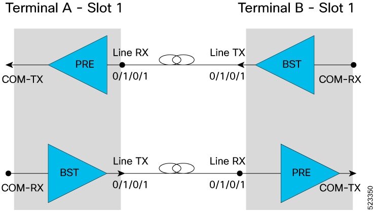
Terminal-to-terminal use case

Terminal node A (IP address: 192.0.2.144(IPv4) or 2001:DB8:4491:2000::229:144(IPv6)) with a EDFA in slot number 1 connected to the EDFA in slot number 1 of Terminal node B (IP address: 192.0.2.146(IPv4) or 2001:DB8:4491:2000::229:146(IPv6)).

Figure 1. Terminal-to-terminal span loss topology

For each EDFA module, it is necessary to configure remote node feature and the span loss using these CLI commands:

Terminal A configurations using IPv4 and IPv6:

#configure terminal (IPv4) 
(config)# hw-module location 0/RP0/CPU0 slot 1 ampli remote-node local-ipv4 192.0.2.144  remote-ipv4 192.0.2.146 remote-slot-id 1
config)#hw-module location 0/RP0/CPU0 slot 1 ampli span-loss
(config)#commit
(config)#end
#configure terminal (IPv6) 
config)# hw-module location 0/RP0/CPU0 slot 1 ampli remote-node local-ipv6 2001:DB8:4491:2000::229:144  remote-ipv6 2001:DB8:4491:2000::229:146 remote-slot-id 1
config)#hw-module location 0/RP0/CPU0 slot 1 ampli span-loss
(config)#commit
(config)#end

Terminal B Configurations using IPv4 and IPv6:

#configure terminal (IPv4) 
(config)# hw-module location 0/RP0/CPU0 slot 1 ampli remote-node local-ipv4 192.0.2.146 remote-ipv4 192.0.2.144 remote-slot-id 1
config)#hw-module location 0/RP0/CPU0 slot 1 ampli span-loss
(config)#commit
(config)#end
#configure terminal (IPv6) 
(config)# hw-module location 0/RP0/CPU0 slot 1 ampli remote-node local-ipv6 2001:DB8:4491:2000::229:146  remote-ipv6 2001:DB8:4491:2000::229:144 remote-slot-id 1
config)#hw-module location 0/RP0/CPU0 slot 1 ampli span-loss
(config)#commit
(config)#end

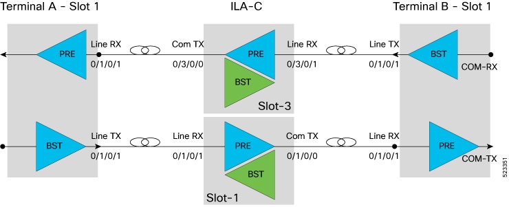
Terminal-to-ILA-to-terminal use case

Terminal A (IP address: 192.0.2.144(IPv4) or 2001:DB8:4491:2000::229:144(IPv6)) with a EDFA in slot number 1 with COM-TX port connected to LINE-RX EDFA in slot 1 ILA-C (IP address: 192.0.2.145(IPv4) or 2001:DB8:4491:2000::229:145(IPv6))

ILA C with a EDFA in slot number 1 with COM-TX port connected to LINE-RX EDFA in slot 1 of Terminal B (IP address: 192.0.2.146 (IPv4) or 2001:DB8:4491:2000::229:146)

ILA C with a EDFA in slot number 3 with COM-TX port connected to LINE-RX EDFA in slot 1 Terminal A

Terminal B with a EDFA in slot number 1 with COM-TX port connected to LINE-RX EDFA in slot 3 ILA.

Figure 2. Terminal-to-ILA-to-terminal span loss topology

Terminal A Configuration using IPv4 and IPv6:

#configure terminal (IPv4) 
(config)# hw-module location 0/RP0/CPU0 slot 1 ampli remote-node local-ipv4 192.0.2.144 remote-ipv4 192.0.2.145 remote-slot-id 1
config)#hw-module location 0/RP0/CPU0 slot 1 ampli span-loss
(config)#commit
(config)#end
#configure terminal (IPv6) 
(config)# hw-module location 0/RP0/CPU0 slot 1 ampli remote-node local-ipv6 2001:DB8:4491:2000::229:144  remote-ipv6 2001:DB8:4491:2000::229:145 remote-slot-id 1
config)#hw-module location 0/RP0/CPU0 slot 1 ampli span-loss
(config)#commit
(config)#end

ILA Configuration using IPv4 and IPv6:

#configure terminal (IPv4)  
(config)# hw-module location 0/RP0/CPU0 slot 1 ampli remote-node local-ipv4 192.0.2.145 remote-ipv4 192.0.2.146 remote-slot-id 1
config)#hw-module location 0/RP0/CPU0 slot 1 ampli span-loss
(config)#commit
(config)#end
#configure terminal (IPv6) 
(config)# hw-module location 0/RP0/CPU0 slot 1 ampli remote-node local-ipv6 2001:DB8:4491:2000::229:145  remote-ipv6 2001:DB8:4491:2000::229:146 remote-slot-id 1
config)#hw-module location 0/RP0/CPU0 slot 1 ampli span-loss
(config)#commit
(config)#end
#configure terminal (IPv4) 
(config)# hw-module location 0/RP0/CPU0 slot 3 ampli remote-node local-ipv4 192.0.2.145 remote-ipv4 192.0.2.144 remote-slot-id 1
config)#hw-module location 0/RP0/CPU0 slot 1 ampli span-loss
(config)#commit
(config)#end
#configure terminal (IPv6) 
(config)# hw-module location 0/RP0/CPU0 slot 3 ampli remote-node local-ipv6 2001:DB8:4491:2000::229:145  remote-ipv6 2001:DB8:4491:2000::229:144 remote-slot-id 1
config)#hw-module location 0/RP0/CPU0 slot 1 ampli span-loss
(config)#commit
(config)#end

Terminal B Configuration using IPv4 and IPv6:

#configure terminal (IPv4) 
(config)# hw-module location 0/RP0/CPU0 slot 1 ampli remote-node local-ipv4 192.0.2.146 remote-ipv4 192.0.2.145 remote-slot-id 3
config)#hw-module location 0/RP0/CPU0 slot 1 ampli span-loss
(config)#commit
(config)#end
#configure terminal (IPv6)
(config)# hw-module location 0/RP0/CPU0 slot 3 ampli remote-node local-ipv6 2001:DB8:4491:2000::229:146  remote-ipv6 2001:DB8:4491:2000::229:145 remote-slot-id 3
config)#hw-module location 0/RP0/CPU0 slot 3 ampli span-loss
(config)#commit
(config)#end

Display span loss calculation

After the feature is enabled and the first calculation runs, the show controllers ots command displays RX Span Loss and TX Span Loss. These values are calculated from the difference between TX Total Power and RX Total Power at the span edge.

Procedure

1.

Display span loss for a TERM node line port.

Example:

#show controllers ots 0/1/0/1
RX Span Loss = 15.20 dB
TX Span Loss = 14.80 dB
2.

For an ILA node, display RX Span Loss on the line port and TX Span Loss on the COM port.

Example:

#show controllers ots 0/3/0/1
RX Span Loss = 12.40 dB
#show controllers ots 0/3/0/0
TX Span Loss = 11.90 dB