Configuration Guide for Cisco NCS 1001, IOS XR Release 25.x.x

PDF

Configuration Guide for Cisco NCS 1001, IOS XR Release 25.x.x

Protection switching module

Want to summarize with AI?

Log in

This topic describes the NCS1K-PSM protection switching module, including TX and RX switching functions, front-panel callouts, protected and working path ports, and controller-to-port mappings.


The protection switching module (NCS1K-PSM) is an NCS 1001 optical module that switches traffic between working and protected optical paths.

  • TX section functions include these behaviors:

    • Splits input optical channels to both working and protection lines.

    • Forces the switch at the remote site by opening one of the two line paths. This is achieved by placing the related variable optical attenuator into automatic VOA shutdown.

  • RX section functions include these behaviors:

    • Selects signals from the working or protection line, and monitors each line through a photodiode.

    • Balances the two line losses by changing the variable optical attenuator attenuation value when the switch changes state.

PSM front view

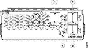
Figure 1. PSM front view

PSM front view

Table 1. PSM front view callouts

1

Protected path input and output port [P - RX, TX]

2

Working path input and output port [W - RX, TX]

3

COM input and output port [COM - RX, TX]

4

Status LED

Controller and optical port mappings

This table describes the mapping of controllers and optical ports for the protection switching module.

Table 2. Controller and optical port mappings

Controller

Optical ports

Ots 0/slot/0/0

COM-TX

Ots 0/slot/0/1

Working path input and output port [W - RX, TX]

Ots 0/slot/0/2

Protected path input and output port [P - RX, TX]


Configure a protection switching module

Configure the PSM slot with the protection behavior required for the working or protected path.

For details about supported PSM parameters, see PSM module configuration parameters. For details about PSM section and path protection topologies, see PSM section and path protection.

Procedure

1.

Enter configuration mode.

Example:

configure terminal
2.

Use the hw-module location command to configure the required PSM parameter on the selected slot.

Example:

hw-module location 0/RP0/CPU0 slot 2 psm lockout-from "working"
3.

Commit the configuration.

Example:

commit

The PSM configuration is committed for the selected slot.

What to do next

For details about manual switching, see Switch a PSM path manually. For details about manual threshold values, see PSM manual threshold guidelines.


PSM module configuration parameters

Use this reference to choose the PSM parameter for the required protection switching behavior.

This table provides information about the PSM configuration parameters.

Table 3. PSM module configuration parameters

Parameter

Description

Values

lockout-from

Excludes the selected port from protection.

Triggers a switch when the active port is specified in the lockout.

For example, configuring lockout-from working triggers a switch to protect when the working port is active.

Configuring lockout-from protected triggers a switch to working when the protected port is active.

Working, Protected

path-protection

Enables PSM path protection.

section-protection

Enables PSM section protection.

uni-dir

Enables PSM unidirectional switching.

auto-threshold

Enables the PSM automatic threshold setting.


Switch a PSM path manually

Apply a manual switch command to move traffic to the working or protected PSM path.

A user-command switch from the path without the ILA node is bidirectional. If the ILA and terminal nodes are in section protection, manual and lockout switch commands from the path with the ILA node are unidirectional.

Note

An FPD upgrade on FW_PSMv1 from FW 1.43 and FW 1.44 to FW 1.45 affects traffic.

Procedure

Use the hw-module command to switch the selected PSM slot to the working or protected path.

hw-module slot slot-number manual-switch-to working | protected

The selected PSM slot switches traffic to the requested path.


PSM section and path protection

PSM section and path protection are protection schemes that use PSM parameters on paired modules to control working and protected optical paths.

Section protection topology

Figure 2. Section protection topology
Section protection topology

Section protection topology is available from Release 6.2.1. You can set the section protection parameter on both PSMs. Insert the PSM in slot 2 for a section protection topology. Connect the EDFA in slot 1 to the protected port on the PSM. Connect the EDFA in slot 3 to the working port of the PSM.

Note

To measure the correct switching time when testing section protection, wait 120 seconds between any two switching events or between a switching event and restoration. This waiting period allows the EDFAs to stabilize after the first switch. It also prevents power at the PSM from oscillating around the threshold.

Path protection topology

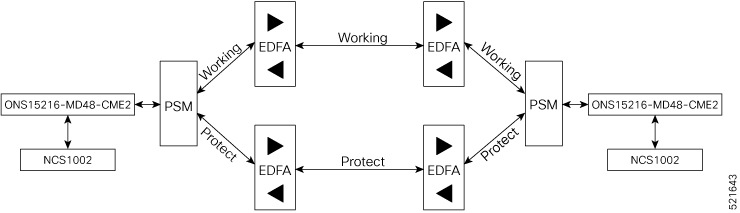
Figure 3. Path protection topology
Path protection topology

Path protection topology is available from Release 6.3.2. You can set the path protection parameter on both the PSMs.


PSM manual threshold guidelines

Use this reference to choose manual RX-low threshold values for PSM path protection and three-way topology deployments.

The switch operates in all conditions when autothreshold is enabled. When path protection is configured with a manual threshold, use these guidelines:

  • During the first installation, set the PSM RX-low threshold three dB less than the minimum power for a single channel. The value must allow the PSM to switch on with a single channel or when the EDFA is in APR (+8 dBm).

  • When the system is running with the final number of channels, set the PSM RX-low threshold three dB less than the target power.

  • After a fiber cut and restore, set the PSM RX-low threshold to a value similar to the value used during the first installation so the PSM can switch on.

PSM autothreshold configuration is highly recommended for a three-way topology.

In a three-way topology, incorrect manual threshold configuration can cause these issues:

  • The switch may not be bidirectional.

  • A double switch can occur on PSM path protection when it is set in three-way configuration.

You can configure parameters such as rx-enable and tx-enable in OTS controllers 1 or 2. These controllers represent the working or protected port of the PSM card.

For details about OTS controllers, see Configure an OTS controller.


PSM autothreshold behavior

Use this reference to understand how PSM autothreshold changes current RX-low thresholds for working and protected RX ports.

PSM threshold behavior depends on whether autothreshold is enabled.

  • When autothreshold is not enabled, the active RX-low threshold value on PSM working and protected RX ports is either the value configured by the user or the default value.

  • The current threshold equals the configured value if the configured values are available in the show controller command output.

  • The current threshold is –38 dBm when the user has not configured a value for the threshold parameters.

When autothreshold is enabled on the PSM card, the RX-low threshold values configured by the user for ports 1 and 2 are ignored.

  • If optical power at the Working-RX and Protected-RX ports remains within ±1 dB for two minutes, the related RX-low threshold automatically becomes the RX power minus three dB.

  • If power is not stable, the related thresholds do not change.

  • W-RX and P-RX thresholds are regulated independently.

LOS-P alarm behavior changes how autothreshold maintains or restores RX-low threshold values.

  • When a LOS-P alarm is detected on the working or protected RX port with autothreshold enabled, the related threshold remains the same. This behavior occurs when RX power is less than the related threshold on the working or protected RX port.

  • When the LOS-P alarm clears within the first 30 seconds, the autothreshold mechanism applies. After two minutes of stable RX power, the RX-low threshold becomes the new RX power minus three dB.

  • When LOS-P is present after 30 seconds, the RX-low threshold automatically moves to the values configured by the user.

  • When LOS-P clears, the ordinary autothreshold mechanism is applied again if RX power is higher than the related current threshold.