Use this procedure to connect OTDR and EDFA ports in a terminal node so that OSC and OTDR signals are carried through the expected fiber path.
Connect the OTDR and EDFA ports in the correct order for port 1. If needed, repeat the sequence for the second OTDR port.
In a terminal-node configuration, both the EDFA and OTDR line cards are installed in the same Cisco NCS 1001 system. The OTDR filter combines the EDFA OSC SFP signal with the OTDR signal. It then feeds the combined signal into the EDFA OSC input.
Procedure
| 1. | Connect an LC/LC fiber from the OTDR COM TX port to the EDFA OSC RX port. |
|
| 2. | Connect an LC/LC fiber from the EDFA OSC TX port to the OTDR COM RX port. |
|
| 3. | Connect an LC/LC fiber from the OTDR OSC TX port to the pluggable RX port inserted into the EDFA. |
|
| 4. | Connect an LC/LC fiber from the pluggable TX port inserted into the EDFA to the OTDR OSC RX port. The port 1 terminal-node cabling path is complete. If you need to connect a second OTDR port, repeat the sequence. 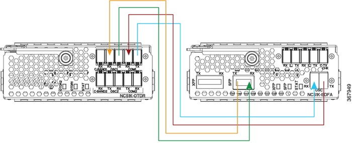
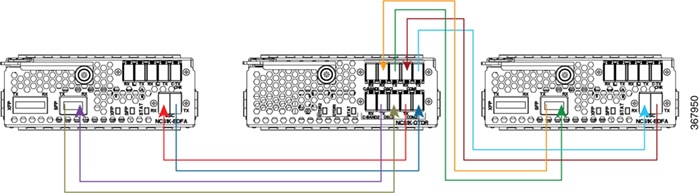
|
The terminal node cabling supports OTDR measurement through the EDFA OSC path.