Cisco C9610 Series Smart Switches Hardware Installation Guide

PDF

Fan tray assembly

Want to summarize with AI?

Log in

Overview

Describes the fan tray assembly on Cisco C9610 series smart switches.

The Cisco C9610 Series Smart Switches consist of four fan trays. Each fan tray (C9610-FAN) consists of six fans and a connector. If one of the fans is not functioning and you need to replace the fan, you must order a fan tray; individual fans cannot be ordered.

When the system is powered on, all four fan trays must be present, or the system will not initialize.

The fans cool the entire chassis and interface with environmental monitors to trigger alarms when conditions exceed thresholds. Fan trays provide cooling critical for the switch operation, which could otherwise result in the switch being nonoperational or cause permanent damage to modules or components.

The features of a Cisco C9610 fan tray include

  • four fan tray slots in the rear panel of the chassis.

  • six 80 x 80 x 80 mm fans per tray.

  • fan tray modules are installed from the rear to enable front-to-back airflow.

  • optimizes the fan-speed for temperature and pressure, and maintains the minimum fan speeds that the chassis requires, in ambient conditions.

This figure shows C9610-FAN with the major components identified.
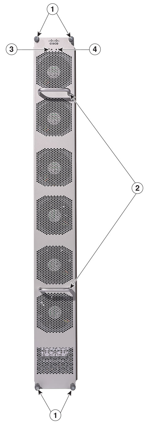
Figure 1. Fan tray assembly

1

Captive installation screws

3

Fan tray status LED

2

Fan tray handles

6

Blue beacon LED for the fan tray


Fan high availability

To ensure high availability, the system responds to fan failures by either minimizing the impact or by compensating and operating at a worst case scenario specification.

  • Boot up: When you power on the switch, all four fan trays must be present, or else, the system will not boot, and the console displays this override message.
    "[HWMSG] FAN_ABSENT: Shutdown now"
  • Runtime: During system runtime if one fan tray is removed from the chassis, the system will still operate; however, the console displays this warning message, and the show hardware led command output will display the system and chassis fan tray status LEDs as red.

    *Aug 12 09:10:43.627 UTC: %CMRP_PFU-2-FAN_POLICY_CRITICAL: Chassis 1 R0/0: 
    cmand: SYSTEM FAN POLICY Critical : MAJOR ALARM - One Fantray Missing!!
    
  • If you remove two or more fan trays from the chassis, a 180 seconds countdown starts. The console displays this override message
    *Jun 16 09:40:07.975: %CMRP_PFU-1-FAN_POLICY_ALERT: R0/0: 
    cmand: SYSTEM FAN POLICY Alert : FAN policy shutdown with reason CRITICAL ALARM: 
    Two or more Fantrays missing!!. Restore working FAN or system will be 
    shutdown in 180 seconds
    
    and the system is shut down after 180 seconds.

Thresholds, alarms, and abnormal acoustic conditions

In normal operating conditions, if no temperature alarms are triggered, the software (if IOS XE software is booted up) controls the fan speed. If the system is in ROMMON mode, the hardware controls the fan speed.
If system temperature alarms are triggered, the software displays an error message indicating that the temperature is high, and fans are operating at higher speed. See the System Management Guide for more information.

If two or more fans fail, you must replace the fan tray within 180 seconds or power down the system. If the temperature exceeds the shutdown threshold, software powers the system down. When the fan trays operate at full speed, increased noise levels can be expected.

The fan trays may operate at 90% of the maximum speed in these circumstances:

  • If two or more fans have failed.

  • If the ASIC thermal sensors hit major, critical, or shutdown thresholds.

  • If one fan tray is removed (with or without additional fan failures).

  • Due to high ambient temperature.