Different ways of installing the C9610 switch chassis.
This section describes the different methods to install the Cisco C9610 series smart switches.
Install the switch on 19-inch shelf brackets.
Install the switch on 23-inch shelf brackets.
Install the switch in Network Equipment-Building System (NEBS)-compliant mode.
Install the switch on 19-inch shelf brackets
To install the switch on 19-inch shelf brackets
If required, attach the cable guides on the chassis with the preinstalled L-brackets, then
rack-mount the chassis.
Attach cable guides on the chassis with preinstalled L-brackets
You can also install the chassis on 19-inch shelf brackets, without attaching the cable guides.
The 19-inch shelf brackets are part of the standard accessory kit, C9610-19-KIT-4 that is shipped with the switch. The cable guides or cable management brackets are optional accessories.
Before you begin
Open the accessory kit and ensure that you have received all items.
Two sets of backplates are part of the 53-102061-01 kit. The backplates are not used for 19-inch rack mounting, but for 23-inch rack mounting.
Procedure
1.
Remove and discard the two L-brackets and the 20 mounting screws that the chassis is shipped with. Do not re-use them during any part of the installation process.
2.
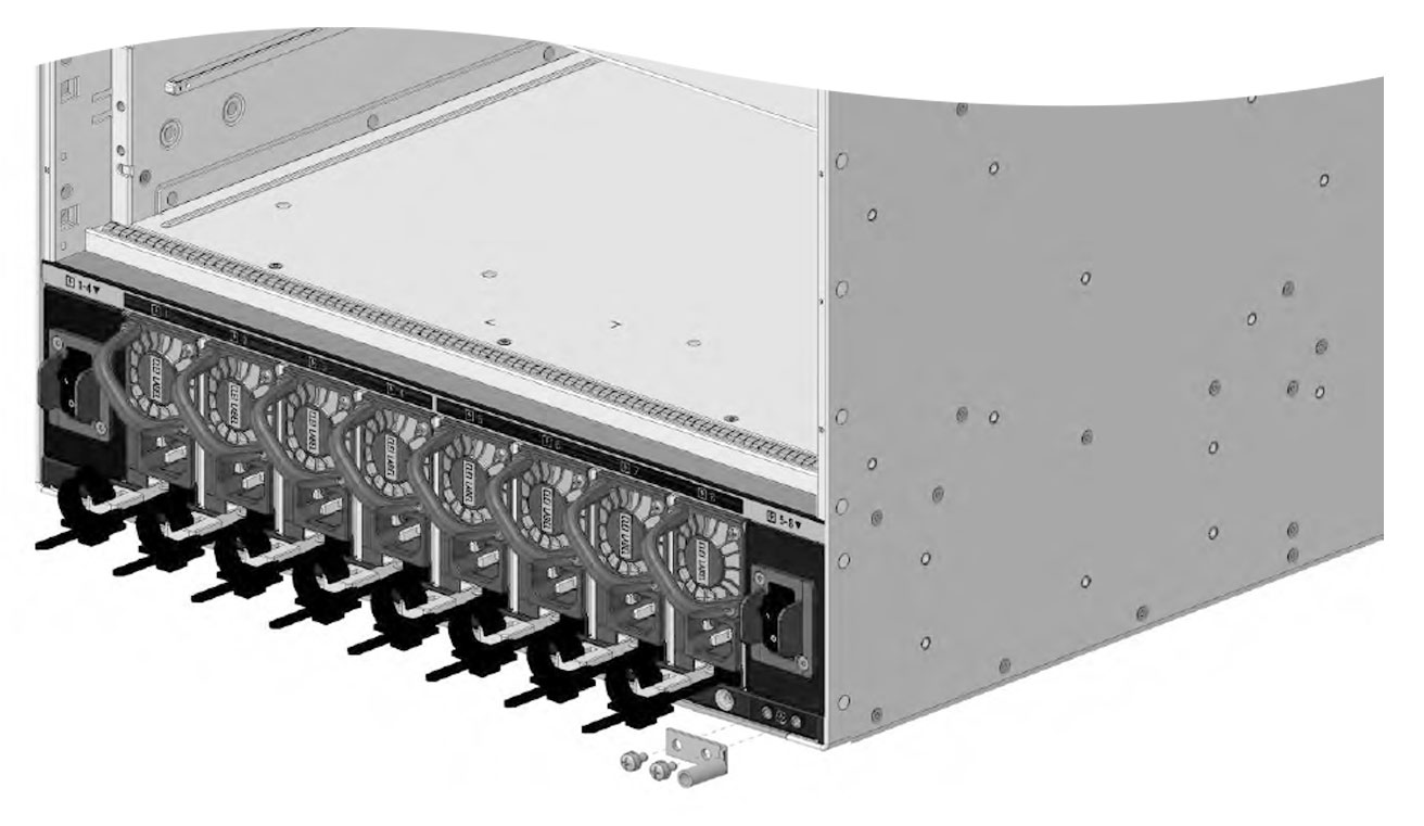
Position the cable guides to align with the L-brackets preinstalled on the chassis.
3.
Secure the cable guides to the L-brackets using a screw on each side.
Use the M3 pan head screw from the 53-102061-01 kit.
4.
Position the preinstalled L-brackets on the chassis to align with the rack rails.
5.
Secure the L-brackets and cable guides to the rack rails by using 13 screws on each side.
Use either 10-32, 12-24, or M6 pan head screws from the C9610-19-KIT-4 kit.
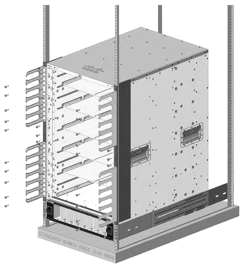
Figure 1. Chassis with cable guides attached
Attaching cable guides on 19-inch shelf brackets is complete.
Rack-mounting the chassis on 19-inch brackets
Install the shelf brackets before you install the chassis in the rack to help support the weight of the chassis while you secure the L-brackets to the rack enclosure. You have to mount the shelf brackets from the front and rear.
Determine the clearance between the insides of the left and right rails of your rack system and install the shelf brackets accordingly.
Ensure that you have the required tools and accessories.
Number 1 and number 2 Phillips screwdrivers
3/16-inch flat-blade screwdriver
Tape measure and level
Before you begin
Warning
Statement 1006—Chassis Warning for Rack-Mounting and Servicing
To prevent bodily injury when mounting or servicing this unit in a rack, you must take special precautions to ensure that the system remains stable. The following guidelines are provided to ensure your safety:
This unit should be mounted at the bottom of the rack if it is the only unit in the rack.
When mounting this unit in a partially filled rack, load the rack from the bottom to the top with the heaviest component at the bottom of the rack.
If the rack is provided with stabilizing devices, install the stabilizers before mounting or servicing the unit in the rack.
Warning
Statement 1032—Lifting the Chassis
To prevent personal injury or damage to the chassis, never attempt to lift or tilt the chassis using the handles on modules, such as power supplies, fans, or cards. These types of handles are not designed to support the weight of the unit.
Warning
Statement 1098— Lifting Requirement
Two or more people are required to lift the heavy parts of the product. To prevent injury, keep your back straight and lift with your legs, not your back.
Procedure
1.
Remove and discard the two L-brackets and the 20 mounting screws that the chassis is shipped with. Do not re-use them during any part of the installation process.
2.
Assemble the left and right shelf brackets on to the rack.
Position the support flanges of the left and right shelf brackets onto the front and rear of the left and right rails respectively.
Align and secure the brackets to the rack by using 16 screws on each side.
Use 10-32, 12-24, or M6 pan head screws from the standard accessory kit. Use the same type of screws for the left and right shelf brackets.
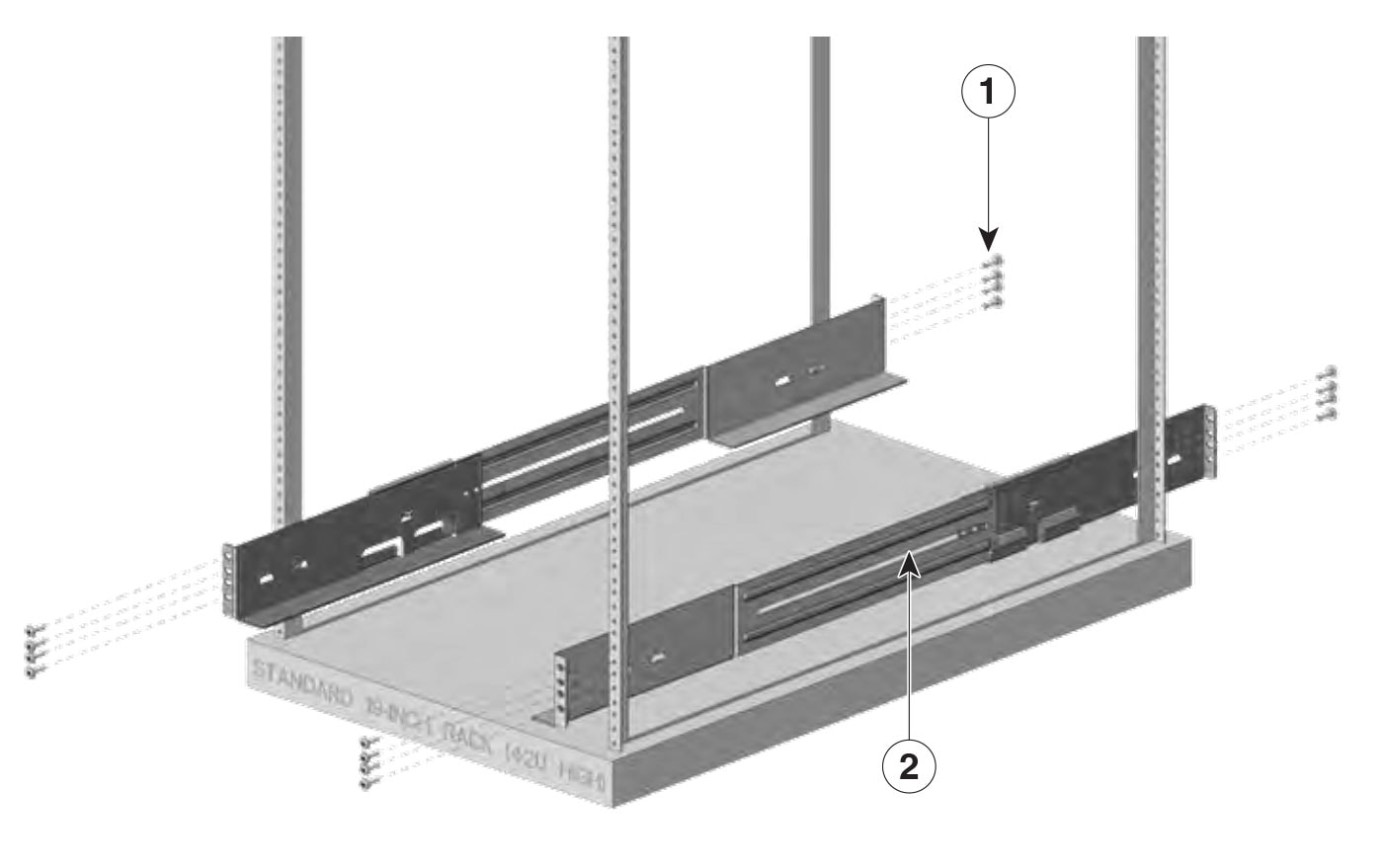
Figure 2. Assembling the shelf brackets on the rack
1
Pan head screws
2
Shelf brackets
3.
Insert the chassis between the shelf brackets and slide it in.
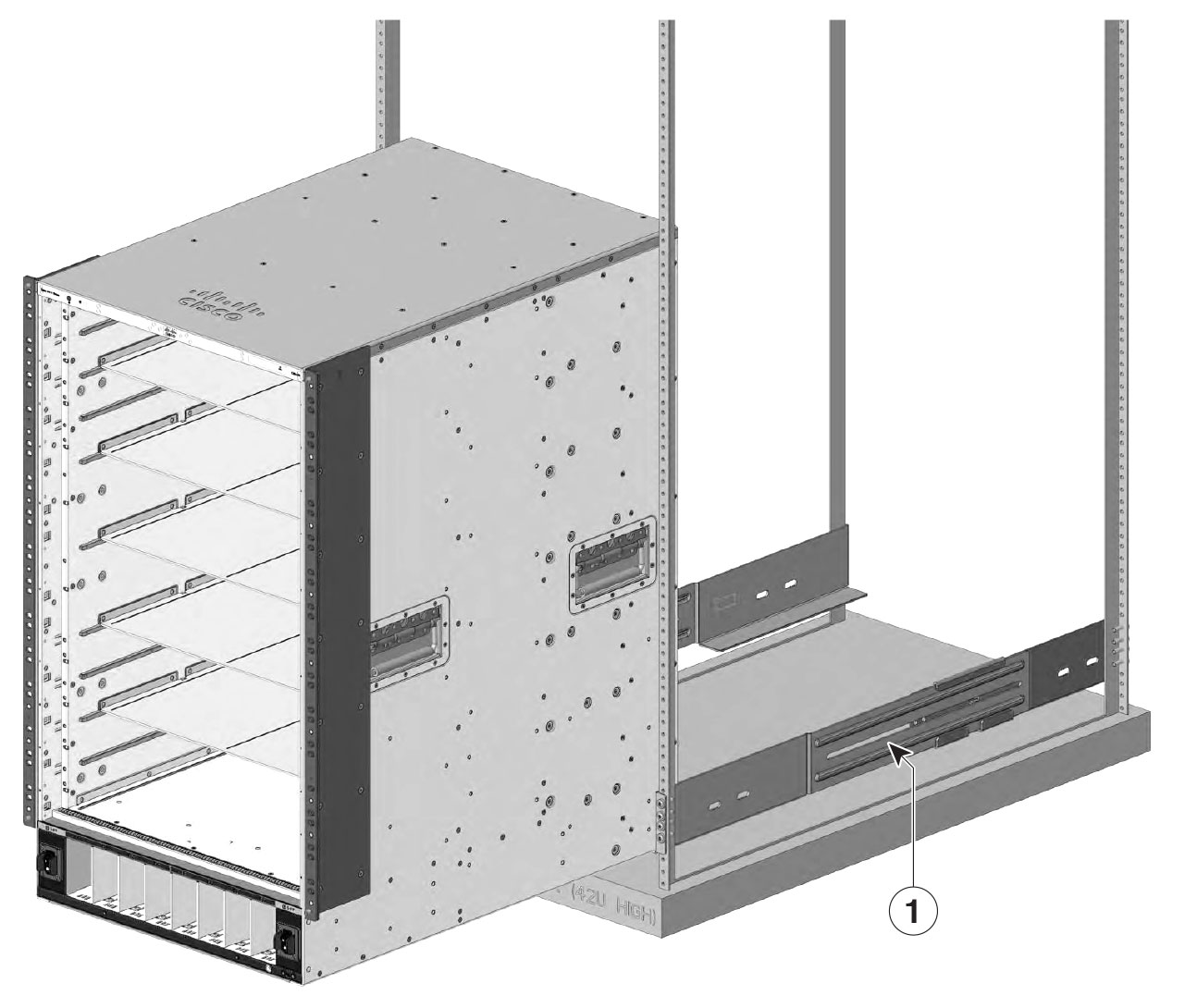
Figure 3. Inserting the chassis between the shelf brackets
1
Shelf brackets
-
-
4.
Align the mounting holes in the L-brackets with the rack rails or on the cable mount (if installed) with the mounting holes in the equipment rack.
Use 13 screws on each side to mount the brackets.
5.
Assemble and mount both the chassis rear-mounting brackets on to the chassis from rear.
Mount the brackets using three screws on each side.
6.
Assemble and mount both the rear rack-mounting brackets on to the rack.
Mount the brackets using four screws on each side.
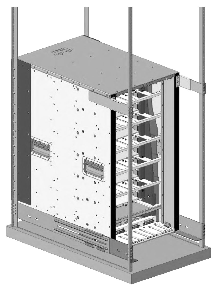
Figure 4. Attaching the rear rack-mounting brackets
7.
Use a tape measure and level to ensure that the chassis is installed straight and level.
What to do next
After installing the chassis in its location, complete the installation process by
connecting the chassis to system ground,
installing and connecting the power supplies to the power source,
connecting the network interface cables to the supervisor module and line card modules. This may involve installing transceivers before you attach the network interface cables, and
powering up the chassis and verifying the installation.
Install the switch in NEBS-compliant mode
This section describes
The NEBS-compliant air filter.
How to install the NEBS-compliant cable guides.
How to rack mount the Cisco C9610 series smart switches in NEBS-compliant mode.
NEBS-compliant air filter
An NEBS-compliant installation allows filtered, front-to-rear airflow. To mount the chassis in NEBS-compliant mode with the air filter, use a 19-inch rack mount. Filter brackets that are mounted on the side of the chassis to hold the air filter.
A 19-inch rack mount is used for mounting the switch in a standard 19 inches (48.26 cms) equipment rack with two unobstructed outer posts. This kit is not suitable for racks with obstructions (such as a power strip) that could impair access to the field-replaceable units (FRUs) of the switch.
Rack mount the chassis in NEBS-compliant mode
Before you begin
Read the safety warnings carefully before starting any installation procedure to make sure you understand the hazards and precautions.
Place the chassis on the floor or on a sturdy table as close as possible to the rack. Leave enough clearance to allow you to move around the chassis.
Open the NEBS rack-mount kit (C9610-NEBS-KIT=) and verify that all parts are included.
Make sure that you have the required tools and accessories.
Phillips screwdriver with a torque capability
Cable management brackets
Note
Some equipment racks provide a power strip along the length of one of the rear posts. If your rack has this feature, consider the position of the strip when planning fastener points. Before installing the brackets on the chassis, determine whether to install the chassis from the front or the rear of the rack.
Perform this task to rack mounting the switch in NEBS-compliant mode.
Position the cable guides to align with the vertical mounting brackets preinstalled on the chassis and secure the cable guides to the vertical mounting brackets.
Use the M3 pan head screws from the C9610-NEBS-KIT to secure the cable guides to the vertical mounting brackets.
3.
Secure the left and right cable guides to the chassis.
Use the pan head screws provided in the standard accessory kit, C9610-19-KIT-4.
4.
Install the top and bottom hood covers.
Position the top and bottom hood assembly in between the left and right cable guides, and secure the hoods.
Use flat head M3 screws from the C9610-NEBS-KIT to secure the top and bottom hood assembly.
5.
Install the right and the left doors.
Position the door frames to align with the cable guides, and pull in the two protruding spring pins so that the pins are held inside the door frames.
Align the spring pins to the holes in the bottom of the door plates, and then release the spring pins, so that the spring pins are inserted into the holes.
Ensure the spring pins are properly inserted into the holes so that the doors can freely swing open on the spring pins.
6.
Install the shoulder screws at the top and bottom of both the door frames to secure the door.
Use the number 4 Allen tool to fix the four screws.
7.
Attach the grounding cable on the left and right to the cable guides.
Use M3 pan head screws from C9610-NEBS-KIT.
8.
To replace the NEBS air filter, open either the right or left door assembly, and remove the air filter.
Use the Philips screwdriver to remove screws of the door assembly.
9.
Install the new air filter from C9610-NEBSFILTER kit, and then install the removed door assembly
Use the screws removed in Step 8 to install the doors.
Establish system ground
Perform these steps to attach the grounding lug and cable to the grounding pad.
Grounding lug can be installed on the front and rear of the chassis.
Before you begin
Warning
Statement 1046—Installing or Replacing the Unit
To reduce risk of electric shock, when installing or replacing the unit, the ground connection must always be made first and disconnected last.
If your unit has modules, secure them with the provided screws.
To connect the system ground, you require these tools and materials:
Grounding lug: a two-hole grounding lug, which supports up to 6 American Wire Gauge (AWG) size. Supplied as part of the standard accessory kit.
Grounding screws: two M4 x 8 mm (metric) pan-head screws. Supplied as part of the standard accessory kit.
Grounding wire: the grounding wire should be sized according to local and national installation requirements. Depending on the power supply and system, a 12 to 6 AWG copper conductor is required for U.S. installations. Commercially available 6-AWG wire is recommended. The length of the grounding wire depends on the proximity of the switch to proper grounding facilities.
No. 1 Phillips screwdriver.
Crimping tool to crimp the grounding wire to the grounding lug.
Wire-stripping tool to remove the insulation from the grounding wire.
Procedure
1.
Use a wire-stripping tool to remove approximately 0.75 inches (19 mm) of the covering from the end of the grounding wire.
2.
Insert the stripped end of the grounding wire into the open end of the grounding lug.
3.
Crimp the grounding wire in the barrel of the grounding lug. Verify that the ground wire is securely attached to the ground lug.
4.
Secure the grounding lug to the system ground connector with two M4 screws. Ensure that the grounding lug and the grounding wire do not interfere with other switch hardware or rack equipment.
5.
Prepare the other end of the grounding wire, and connect it to an appropriate grounding point in your site to ensure adequate earth ground for the switch.
Figure 5. Installing the ground lug from the front of the chassis
Attach an ESD strap
After you install the system ground lug, follow these steps to correctly attach the electrostatic discharge (ESD) wrist strap.
Procedure
1.
Attach the ESD wrist strap to bare skin.
If you are using the ESD wrist strap supplied with the FRUs, open the wrist strap package and unwrap the ESD wrist strap. Place the black conductive loop over your wrist and tighten the strap such that it touches your bare skin well.
If you are using an ESD wrist strap equipped with an alligator clip, open the package and remove the ESD wrist strap. Locate the end of the wrist strap that attaches to your body and secure it to your bare skin.
2.
Grasp the spring or alligator clip on the ESD wrist strap and momentarily touch the clip to a bare metal spot (unpainted surface) on the rack. We recommend that you touch the clip to an unpainted rack rail so that any built-up static charge is then safely dissipated to the entire rack.
3.
Attach either the spring clip or the alligator clip to the ground lug screw as follows:
If you are using the ESD wrist strap that is supplied with the FRUs, squeeze the spring clip jaws open, position the spring clip to one side of the system ground lug screw head, and slide the spring clip over the lug screw head so that the spring clip jaws close behind the lug screw head.
Note
The spring clip jaws do not open wide enough to fit directly over the head of the lug screw or the lug barrel.
f you are using an ESD wrist strap that is equipped with an alligator clip, attach the alligator clip directly over the head of the system ground lug screw or to the system ground lug barrel.
Follow these guidelines, when handling modules.
Handle carriers using the available handles or edges only; avoid touching the printed circuit boards or connectors.
Place a removed component board side (refers to the side of the switch where the main circuit board [PCB] is located) up on an antistatic surface or in a static-shielding container. If you plan to return the component to the factory, immediately place it in a static shielding container.
Never attempt to remove the printed circuit board from the metal carrier.
Caution
For safety, periodically check the resistance value of the antistatic strap. The measurement should be between 1 and 10 megohm (Mohm).