Safety warning to adhere to before installing the Cisco C9610 switch.
Safety warnings appear throughout this publication in procedures that may harm you if you perform them incorrectly. A warning symbol precedes each warning statement. The warnings below are general warnings that are applicable to the entire publication.
Statement 1071—Warning Definition
IMPORTANT SAFETY INSTRUCTIONS
Before you work on any equipment, be aware of the hazards involved with electrical circuitry and be familiar with standard practices for preventing accidents. Read the installation instructions before using, installing, or connecting the system to the power source. Use the statement number at the beginning of each warning statement to locate its translation in the translated safety warnings for this device.
SAVE THESE INSTRUCTIONS

Statement 407—Japanese Safety Instruction
You are strongly advised to read the safety instruction before using the product.
https://www.cisco.com/web/JP/techdoc/pldoc/pldoc.html
When installing the product, use the provided or designated connection cables/power cables/AC adapters.
〈製品使用における安全上の注意〉
www.cisco.com/web/JP/techdoc/index.html
接続ケーブル、電源コードセット、ACアダプタ、バッテリなどの部品は、必ず添付品または
指定品をご使用ください。添付品・指定品以外をご使用になると故障や動作不良、火災の
原因となります。また、電源コードセットは弊社が指定する製品以外の電気機器には使用
できないためご注意ください。
Statement 445—Connect the Chassis to Earth Ground
To reduce the risk of electric shock, connect the chassis of this equipment to permanent earth ground during normal use.
Statement 1008—Class 1 Laser Product
This product is a Class 1 laser product.
Statement 1017—Restricted Area
This unit is intended for installation in restricted access areas. Only skilled, instructed, or qualified personnel can access a restricted access area.
Statement 1029—Blank Faceplates and Cover Panels
Blank faceplates and cover panels serve three important functions: they reduce the risk of electric shock and fire, they contain electromagnetic interference (EMI) that might disrupt other equipment, and they direct the flow of cooling air through the chassis. Do not operate the system unless all cards, faceplates, front covers, and rear covers are in place.
Statement 1049—Rack Installation
To reduce the risk of bodily injury, mount the chassis on a rack that is permanently affixed to the building.
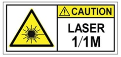
Statement 1055—Class 1/1M Laser
Invisible laser radiation is present. Do not expose to users of telescopic optics. This applies to Class 1/1M laser products.
Statement 1056—Unterminated Fiber Cable
Invisible laser radiation may be emitted from the end of the unterminated fiber cable or connector. Do not view directly with optical instruments. Viewing the laser output with certain optical instruments, for example, eye loupes, magnifiers, and microscopes, within a distance of 100 mm, may pose an eye hazard.
Statement 1074—Comply with Local and National Electrical Codes
To reduce risk of electric shock or fire, installation of the equipment must comply with local and national electrical codes.
Statement 1089—Instructed and Skilled Person Definitions
An instructed person is someone who has been instructed and trained by a skilled person and takes the necessary precautions when working with equipment.
A skilled person or qualified personnel is someone who has training or experience in the equipment technology and understands potential hazards when working with equipment.
Statement 1090—Installation by a Skilled Person
Only a skilled person should be allowed to install, replace, or service this equipment. See statement 1089 for the definition of a skilled person.
Statement 1091—Installation by an Instructed Person or Skilled Person
Only an instructed person or skilled person should be allowed to install, replace, or service this equipment. See statement 1089 for the definition of an instructed person or skilled person.
Statement 1099—Before Connecting to System Power Supply
High touch/leakage current—Permanently connected protective earth ground is essential before connecting to the system power supply.
Statement 8015—Installation Location Network Telecommunications Facilities
This equipment is suitable for installation in network telecommunications facilities.
Statement 8016—Installation Location Where the National Electric Code (NEC) Applies
This equipment is suitable for installation in locations where the NEC applies.
Statement 9001—Product Disposal
Ultimate disposal of this product should be handled according to all national laws and regulations.
NEBS statements
Statement 7003— Shielded Cable Requirements for Intrabuilding Lightning Surge
The intrabuilding port(s) of the equipment or subassembly must use shielded intrabuilding cabling/wiring that is grounded at both ends.
The following port(s) are considered intrabuilding ports on this equipment: RJ-45 Copper Ethernet ports.
Statement 7004— Special Accessories Required to Comply with GR-1089 Emission and Immunity Requirements
To comply with the emission and immunity requirements of GR-1089, shielded cables are required for the following ports: RJ-45 Copper Ethernet ports.
Statement 7005— Intrabuilding Lightning Surge and AC Power Fault
The intrabuilding port(s) of the equipment or subassembly is suitable for connection to intrabuilding or unexposed wiring or cabling only. The intrabuilding port(s) of the equipment or subassembly MUST NOT be metallically connected to interfaces that connect to the OSP or its wiring for more than 6 meters (approximately 20 feet). These interfaces are designed for use as intrabuilding interfaces only (Type 2, 4, or 4a ports as described in GR-1089) and require isolation from the exposed OSP cabling. The addition of primary protectors is not sufficient protection in order to connect these interfaces metallically to an OSP wiring system.
The following ports are considered intrabuilding ports on the equipment: RJ-45 Copper Ethernet ports.
Statement 7012—Equipment Interfacing with AC Power Ports
Connect this equipment to AC mains that are provided with a surge protective device (SPD) at the service equipment that complies with NFPA 70, the National Electrical Code (NEC).
Statement 7013—Equipment Grounding Systems—Common Bonding Network (CBN)
This equipment is suitable for installations using the CBN.
Statement 7015—Equipment Bonding and Grounding
When you use thread-forming screws to bond equipment to its mounting metalwork, remove any paint and nonconductive coatings and clean the joining surfaces. Apply an antioxidant compound before joining the surfaces between the equipment and mounting metalwork.
Statement 7016— Battery Return Conductor
Treat the battery return conductor of this equipment as Isolated DC return (DC-I).
Statement 7018—System Recover Time
The equipment is designed to boot up in less than 30 minutes provided the neighboring devices are fully operational.