Steps to remove and reinsert the power supply units.
Cisco C9610 series smart switches ship with preinstalled power supply modules. This section describes how to remove and install the power supply modules.
Cisco C9610 Series Smart Switches Hardware Installation Guide
Steps to remove and reinsert the power supply units.
Cisco C9610 series smart switches ship with preinstalled power supply modules. This section describes how to remove and install the power supply modules.
To install a power supply unit on a Cisco C9610 switch, you need
Phillips-head screwdriver
10-mm torque driver (with a 3-inch shaft, at a minimum)
Wire-stripping tool
Wire-crimping tool
The chassis supports field-replaceable and hot-swappable AC-input and DC-input power supply modules. You can install a mix of AC-input and DC-input modules in the chassis. This section describes how to remove and install both kinds of modules and safety warnings to adhere to.
In redundant mode, you do not have to power down the switch to replace or upgrade the power supplies.
In combined mode, the module is still hot-swappable as long as the difference between total output power and the total used power is greater than the capacity of the module being removed.
Total output power: Total used > Capacity of power supply module being removed.
Statement 1003—DC Power Disconnection
To reduce risk of electric shock or personal injury, disconnect DC power before removing or replacing components or performing upgrades.
Statement 1005— Circuit Breaker
This product relies on the building’s installation for short-circuit (overcurrent) protection. To reduce risk of electric shock or fire, ensure that the protective device is rated not greater than: 20A for AC and 60A for DC.
Statement 1017—Restricted Area
This unit is intended for installation in restricted access areas. Only skilled, instructed, or qualified personnel can access a restricted access area.
Statement 1022—Disconnect Device
To reduce the risk of electric shock and fire, a readily accessible disconnect device must be incorporated in the fixed wiring.
Statement 1073—No User-Serviceable Parts
There are no serviceable parts inside. To avoid risk of electric shock, do not open.
Statement 1073—No User-Serviceable Parts
There are no serviceable parts inside. To avoid risk of electric shock, do not open.
| 1. | Turn the power switch of the designated power supply module to OFF (0) position. |
|
| 2. | Loosen and remove the retainer strip that is around the power cord. |
|
| 3. | Remove the power cord from the power receptacle on the power supply. |
|
| 4. | Press the release latch at the bottom of the power supply module upwards. 
In PDF, to view the animation, click this link. |
|
| 5. | Grasp the power supply module handle with one hand, and slide the power supply module out fully. 
In PDF, to view the animation, click this link.
|
Set the power supply aside and proceed with installing the new or replacement power supply module. Install blank covers in all power supply bays that are to remain empty (C9600-PWR-BLANK). For information about installing blank covers, see Remove and reinstall power supply blanks.
Statement 1073—No User-Serviceable Parts
There are no serviceable parts inside. To avoid risk of electric shock, do not open.
Ensure that you have installed the cable guide before you begin this procedure. This is to properly guide and arrange the power cords that you will attach as part of the installation.
| 1. | Remove the replacement power supply from its shipping packaging. |
|
| 2. | Verify that the power switch of the replacement power supply is in the OFF (0) position. |
|
| 3. | If installed, remove the blank power supply cover from the empty power supply bay. For information about removing blank covers, see Remove and reinstall power supply blanks. Save the blank cover for future use. |
|
| 4. | Grasp the power supply handle with one hand and slide the power supply all the way into the power supply bay. Make sure that the power supply is fully seated in the bay. 
In PDF, to view the animation, click this link.
|
|
| 5. | Verify that all site power and grounding requirements have been met. |
|
| 6. | Verify that you have the correct power cord for your location and power supply rating and only then plug the power cord connector into the power supply receptacle. |
|
| 7. | Follow the steps to install the power cord retainer, to hold it in place and avoid accidental removal. |
|
| 8. | Set the power switch to the ON (|) position |
Connect the power supply to the power source.
| 1. | Prior to connecting the power supply to a power source, ensure that the chassis is properly grounded. |
|
| 2. | Plug the power cable into the AC power receptacle on the power supply module. |
|
| 3. | Plug the other end of the power cable into a power source supplied by the data center.
|
|
| 4. | Verify that the power supply is receiving power by checking that the LED is on and is green. For more information about the power supply LEDs and the conditions that they indicate, see Power supply module LEDs. When you first activate the power supply, you can verify the functionality of the LED by checking that LED turns on for a couple of seconds. If the LED is flashing amber or green, check the power connections on the power supply and the power source. |
To connect the DC power supply directly to one or two DC power sources, follow these steps.
Statement 1022—Disconnect Device
To reduce the risk of electric shock and fire, a readily accessible disconnect device must be incorporated in the fixed wiring.
Statement 1033—Safety Extra-Low Voltage (SELV)—IEC 60950/ES1–IEC 62368 DC Power Supply
To reduce the risk of electric shock, connect the unit only to a DC power source that complies with the SELV requirements in the IEC 60950-based safety standards or the ES1 requirements in the IEC 62368-based safety standards.
| 1. | Prior to connecting the power supply to a power source, ensure that the chassis is properly grounded. |
|||||
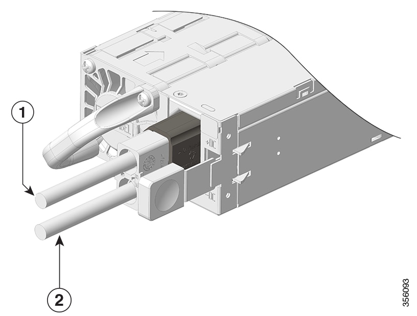
| 2. | Plug the DC power cable into the DC power receptacle on the power supply module. 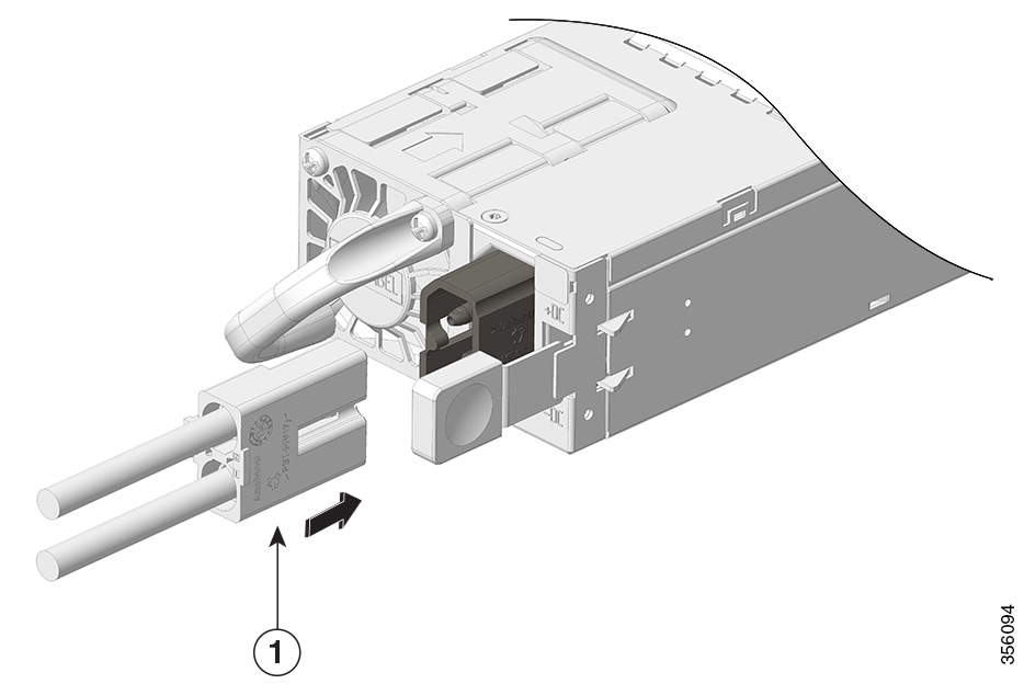
|
|||||
| 3. | Turn off the power at the circuit breakers for the portions of the DC grid power that you are connecting to and verify that all of the LEDs on the DC grid power supplies are off. |
|||||
| 4. | Install the two cables from the DC power cable to a DC power source as follows:
|
|||||
| 5. | Verify that the power supply is receiving power by checking that the LED is on and is green. When you first activate the power supply, you can verify the functionality of the LED by checking that LED turns on for a couple of seconds. If the LED is flashing amber or green, check the power connections on the power supply and the power source. |
| 1. | Verify the power supply operation by checking the power supply’s front-panel LED. See Power supply module LEDs. |
|
| 2. | Check the power supply and system status from the system console by entering show power command in privileged EXEC mode. |
|
| 3. | If the LEDs or show power command output indicate a power problem or other system problem. |
If a power supply bay in a chassis is unused, you must cover it with a power supply blank cover to maintain proper airflow through the chassis. Part number of the power supply blank is C9606-PWR-BLANK=.
Statement 1029—Blank Faceplates and Cover Panels
Blank faceplates and cover panels serve three important functions: they reduce the risk of electric shock and fire, they contain electromagnetic interference (EMI) that might disrupt other equipment, and they direct the flow of cooling air through the chassis. Do not operate the system unless all cards, faceplates, front covers, and rear covers are in place.
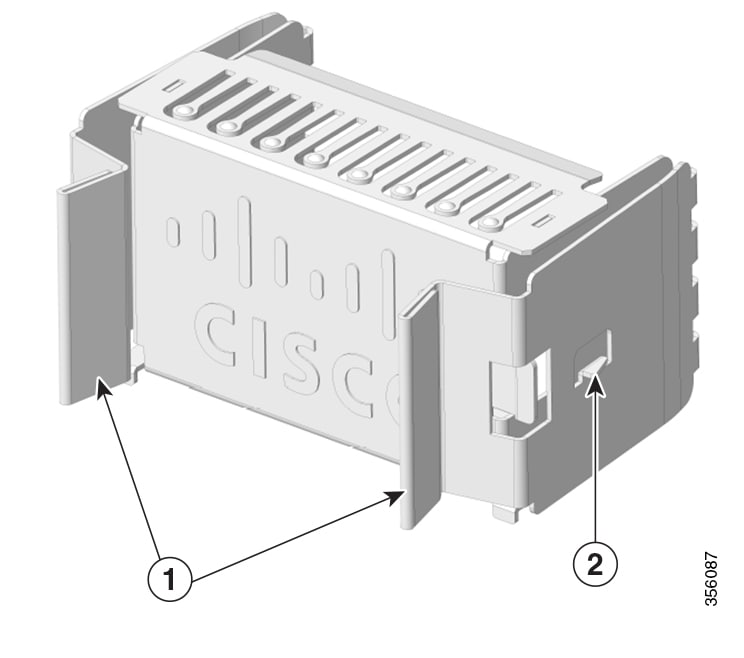
| 1 |
Release handles |
2 |
Retainer clip |
To remove the blank cover from a bay, use the release handles to hold the blank cover (with your thumb and index fingers), squeeze both the handles toward each other and slide the cover out of the bay.
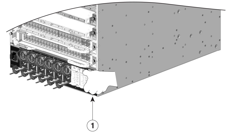
| 1 |
Release handles that are squeezed toward each other |
Do not leave any power supply slot open for any amount of time while the system is powered up. Prior to inserting a new power supply unit, for instance, when replacing the unit, ensure there are no foreign, conductive or other objects, or debris in the slot.
To install a power supply blank cover, push the blank cover straight and into the bay. You will hear retainer clips snap into place when installed correctly. You can hold the blank cover by the outside edges when you perform this task; alternatively, use the release handles to hold the blank cover.
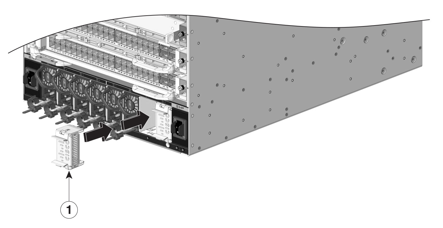
| 1 |
Power supply blank |
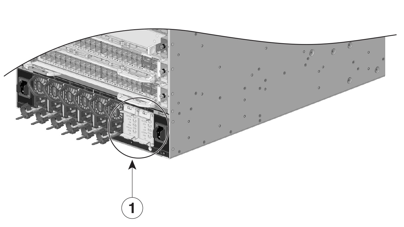
| 1 |
Power supply blanks after installation |
Power supply blank covers can be placed in any slot when fewer than 4 power supplies are installed in a chassis.
If you contact Cisco Technical Assistance, you need to know the serial number. These figures show where the serial number is located. You can also use the show version privileged EXEC command to see the serial number.
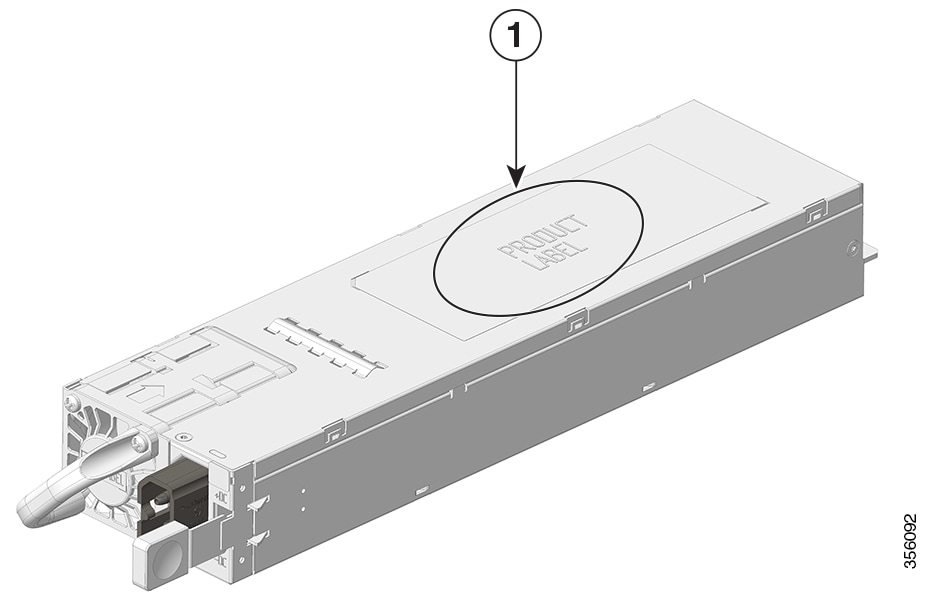
| 1 |
Power supply module serial number |
- |
- |