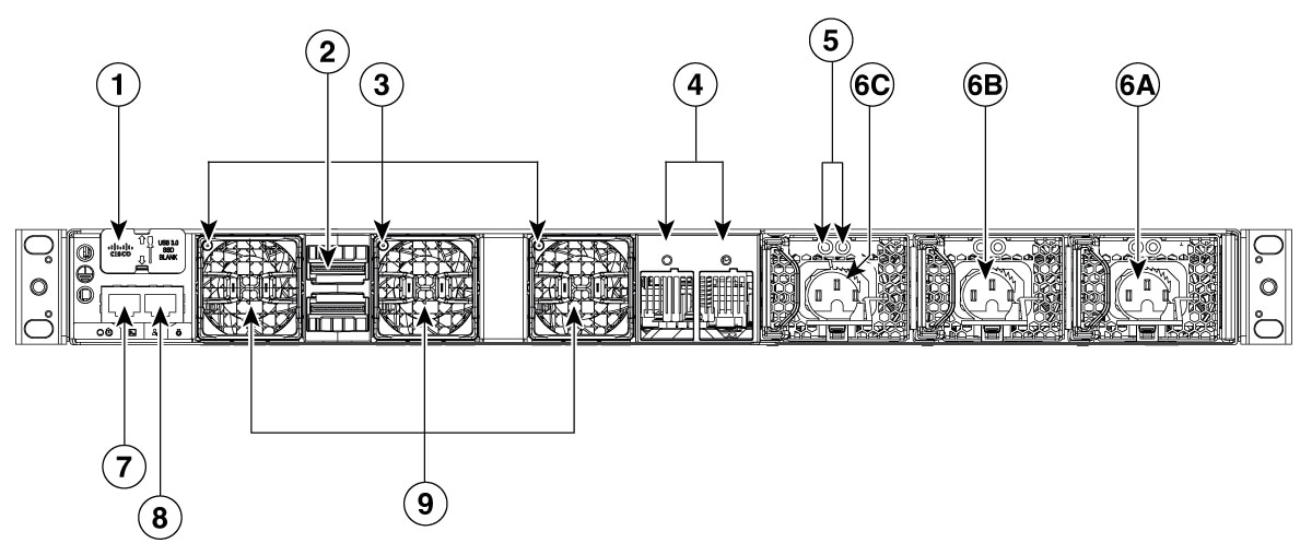
Describes the rear panel of the Cisco C9350 switch.
The rear panel includes StackWise connectors, StackPower connectors, fan modules, and power supply modules.
Figure 1. Rear panel of a C9350-48HX and C9350-48TX
1
USB3.0–SSD port
6
Power supply modules
2
StackWise ports and connectors
7
RJ-45 console port
3
Fan status LEDs
8
Ethernet management port
4
StackPower ports and connectors
9
Fan modules
5
Power supply LEDs
AC OK (input) status LED
PS OK (output) status LED
-
-
Ethernet management port
You can connect the switch to a host such as a Windows workstation or a terminal server through the 10/100/1000/2.5 G Ethernet management port or one of the console ports. The 10/100/1000/2.5 G Ethernet management port is a VPN routing and forwarding (VRF) interface and uses a RJ-45 crossover or straight-through cable.
Note
The 10/100/1000/2.5 G Ethernet management port is an RJ-45 connector that should be connected to a Windows workstation or a terminal server. Do not connect this port to another port in the same switch or to any port within the same switch stack.
This table shows the Ethernet management port LED colors and the description.
Table 1. Ethernet management port LEDs
Color
Description
Green
Link up but no activity.
Blinking green
Link up and activity.
Off
Link down.
Fan modules
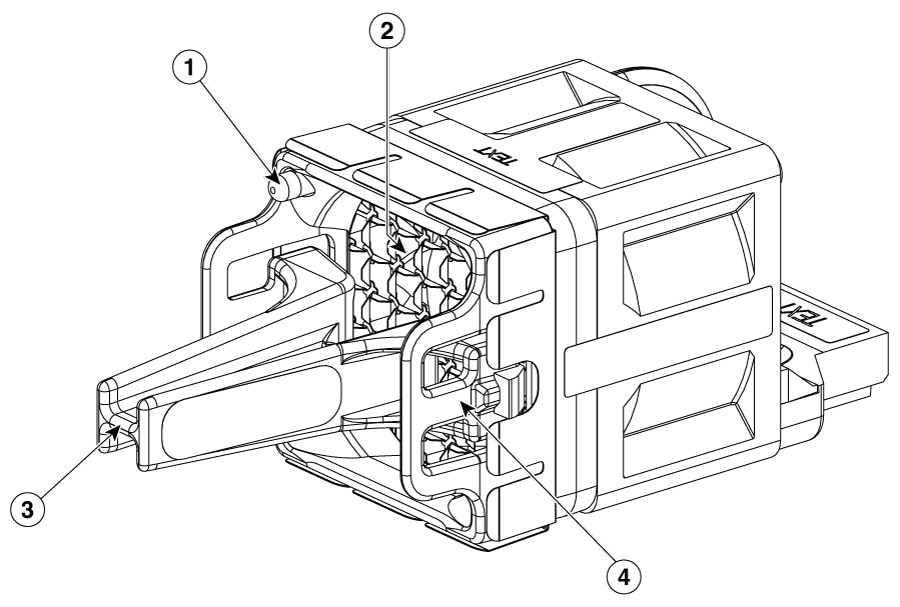
The Cisco C9350 series smart switches have three fan modules at the rear of the switch. The fans are hot-swappable and numbered from left to right.
A powered-on switch should always have more than one operational fan. The switch can operate with two operational fans and one nonfunctional fan, but the failed fan should be replaced as soon as possible to avoid a service interruption due to a second fan fault. A switch with one or more fans failed or removed will operate with fans at a faster speed, producing increased sound.
The switch requires three fans for proper cooling.
Sharp edges on the fan module can cause serious injury. Keep fingers clear.
Figure 2. Fan module
1
Fan LED
3
Extraction handles
2
Exhaust vent
4
Retainer clip
When the fan modules are operating properly, a green LED at the top left corner of the fan assembly (viewed from the rear), is ON. If the fan fails, the LED turns to amber.
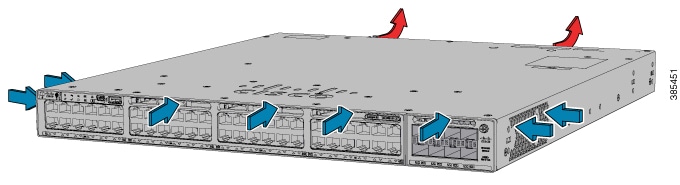
The airflow direction is from front-to-rear and side-to-rear. This illustration shows the airflow pattern for the switches. The blue arrow shows cool airflow, and the red arrow shows warm airflow.
An internal power supply module converts external electrical power (either AC or DC) into the precise DC voltages required to operate the switch's internal components, and also provides PoE to connected devices.
The Cisco C9350 series smart switches have three internal power supply module slots. You can use one, two, or three power supply modules. By default, these switches ship with one power supply module, and you can purchase more power supply modules when you order the switch or at a later date.
These switches can operate with either one, two, or three active power supply modules or with power supplied by a stack. A switch that is in a StackPower stack can operate with power supplied by other switches in the stack.
Caution
A power supply module must be available in the power supply module slot A for efficient system cooling.
To ensure proper airflow, and maintain the recommended operating temperature, follow these power supply installation requirements:
A power supply module must always be installed in slot A. Additional power supplies must be installed sequentially—first in slot B, followed by slot C.
A power supply slot cover must be installed in every unused power supply slot.
The following table describes the supported internal power supply modules. In a switch, a mix of Platinum-certified and Titanium-certified power supply modules is supported.
Table 2. Power supply module part numbers and descriptions
Supported power supply modules
Description
PWR-C2-500WAC-I
500 W AC Platinum-certified power supply module with port-side intake fan
PWR-C2-850WAC-I
850 W AC Platinum-certified power supply module with port-side intake fan
PWR-C2-1600WAC-I
1600W AC Titanium-certified power supply module with port-side intake fan, 1600W high-line input and 1200W low-line input
Power supply module components
Each AC power supply module has a power cord for connection to an AC power outlet. To view the list of available AC power cords, see the AC power cord specifications section.
This section displays the supported power supply modules and the components of each of these.
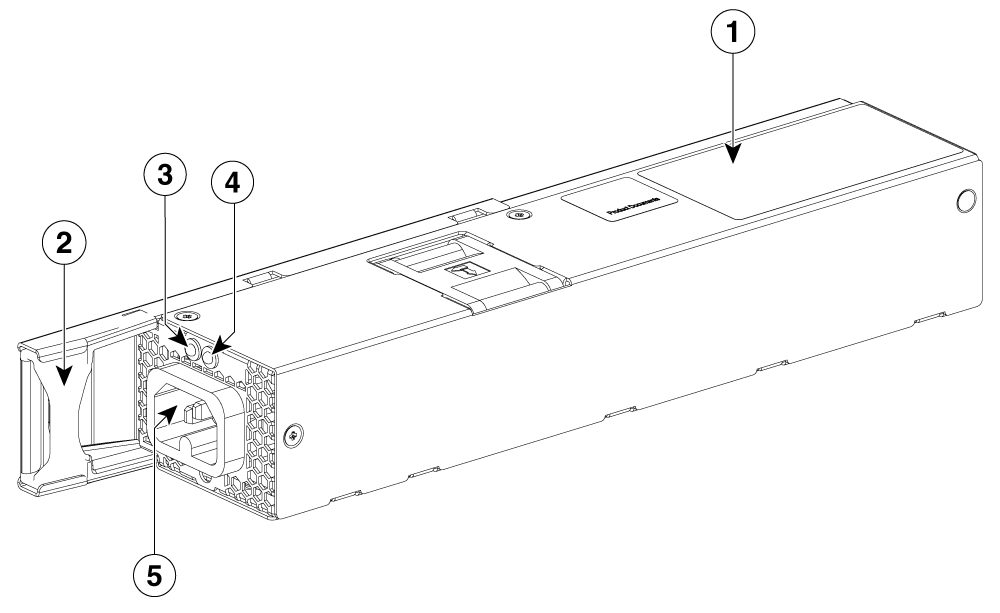
Figure 4. 500W AC power supply
1
500 W AC power supply module
5
AC power cord connector
2
Keying feature
6
Release latch
3
AC OK LED
7
Power cord retainer
4
PS OK LED
-
-
Figure 5. 850 W AC power supply
1
850 W AC power supply module
5
AC power cord connector
2
Keying feature
6
Release latch
3
AC OK LED
7
Power cord retainer
4
PS OK LED
-
-
Figure 6. 1600 W AC power supply
1
1600 W AC power supply module
5
PS OK LED
2
Release latch
6
AC power cord connector
3
AC OK LED
If no power supply is installed in a power supply slot, install a power supply slot cover.
Figure 7. Power supply slot cover
1
Release handles
2
Retainer clips
The power supply LEDs are available at the rear of the switch, next to the power supply modules. This table explains the LEDs and what each color denotes.
Table 3. Switch power supply module LEDs
AC OK
Description
PS OK
Description
Off
No AC input power.
Off
Output is disabled, or input is outside operating range (LED is off).
Green
AC input power present.
Green
Power output to switch active.
Red
Output has failed.
Default power supply modules
All switches ship with a default power supply module. All the power supply modules (except the blank modules) have internal fans.
Caution
Do not operate the switch with one power supply module slot empty. Always install a blank module in the empty slot to keep the operating temperature and fan noise lower.
Caution
A power supply module must be installed in the power supply module Slot A for efficient system cooling.
This table displays the default power supply module that ships with each switch model.
Table 4. Available PoE with default power supply
Switch model
Default power supply
Available PoE
C9350-24HX
PWR-C2-1600WAC
1235W
C9350-48HX
PWR-C2-1600WAC
1120W
C9350-48HXN
PWR-C2-850WAC
470W
C9350-48TX
PWR-C2-500WAC
No PoE
C9350-24P
PWR-C2-850WAC
590W
C9350-48P
PWR-C2-850WAC
590W
C9350-24T
PWR-C2-500WAC
No PoE
C9350-48T
PWR-C2-500WAC
No PoE
C9350-24U
PWR-C2-850WAC
570W
C9350-48U
PWR-C2-850WAC
570W
Power supply modes
Cisco C9350 series smart switches offer redundant and combined configuration modes for power supplies. In both modes, the load is equally distributed among the power supplies.
The system load and number of power supply modules installed determine the power level required by the system from each power supply module, and consequently, the suitable power supply mode. For system power budgeting estimates and to determine power supply requirements, use the Cisco Power Calculator.
To configure a power supply mode, enter the power redundancy-mode command in global configuration mode. If you do not configure a mode, the default mode applies. The default mode is combined mode
Combined mode
In combined mode, the total power available for the entire chassis is equal to the sum of the output of all the power supplies, multiplied by the share ratio. In combined mode, the power supplies can be of different wattage.
Total combined power = P + (N-1) * P * (share ratio), where
P is the power output of one PSU
N is the number of PSUs available on the switch. This can be 1 or 2 or 3.
Redundant N+1 mode
In redundant mode, a given power supply module can either be active, or in a standby mode. In N+1 mode, N is the number of active power supply modules and +1 is the power supply module configured as the standby module.
When you configure the switch with N+1 redundancy, the Cisco IOS XE software ensures that there is a standby power supply available, and that sufficient power is available with the active power supply modules (N). All the power supplies including the active and standby shares the load equally.
However, with a standby power supply installed, the system ensures that the additional output power available with a standby is always reserved for use in case of a failure. If the power supply mode is set to redundant and the total active output power is not sufficient to meet the power requirements, the switch will not enter redundant mode.
RJ-45 console port
The RJ-45 console port is a serial communication port used for device management and configuration. It allows direct access to the device CLI for initial setup, troubleshooting, or recovery when network access is unavailable. The console port transmits serial data rather than Ethernet traffic.
RJ-45 console port LEDs
This table shows the RJ-45 console port LED colors and description.
Color
Description
Green
RJ-45 console port is active.
Off
The port is not active.
StackWise ports
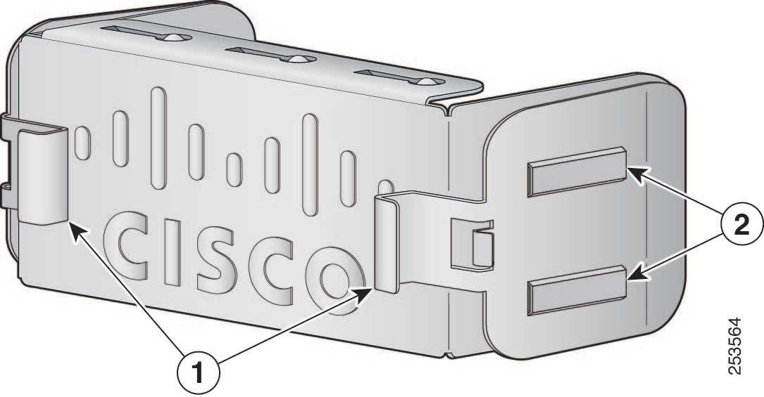
StackWise ports are used to connect switches in StackWise stacking configurations. The switch ships with a 0.5-meter StackWise cable for modular uplink switch models that you can use to connect the StackWise ports. For more information on StackWise cables, see Connecting the StackWise cables.
You can order these StackWise cables from your Cisco sales representative:
STACK-T1A-50CM Cisco StackWise-1.6T 50 cm stacking cable
STACK-T1A-1M Cisco StackWise-1.6T 1 m stacking cable spare
STACK-T1A-3M Cisco StackWise-1.6T 3 m stacking cable spare
Caution
Use only approved cables, and connect only to similar Cisco equipment. Equipment might be damaged if connected to non-approved Cisco cables or equipment.
StackPower connector
The Cisco C9350 switches have a StackPower connector for use with Cisco StackPower cables to configure a switch power stack that includes up to four switches. A power stack can be configured in redundant or power-sharing mode.
You can order these StackPower cables from your Cisco sales representative:
CAB-SPWR-35CM= (0.35-meter cable)
CAB-SPWR-100CM= (1.0-meter cable)
For details about connecting StackPower cables and StackPower guidelines, refer to Plan a StackPower stack section.
USB 3.0 SSD port
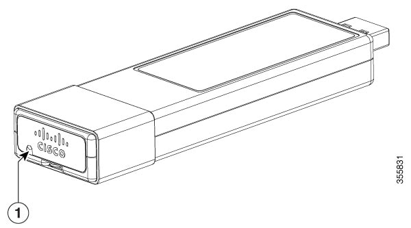
To support the storage needs on the switch, the Cisco C9350 Series Smart Switches provide support for pluggable 120 GB and 240 GB USB 3.0 Solid State Drive (SSD) modules. The USB 3.0 SSD module slot is located at the rear panel of the switch. The storage drive can also be used to save packet captures and trace logs generated by the operating system. The USB 3.0 SSD device is field replaceable.
The USB 3.0 supports an optional 120 GB USB 3.0 SSD (SSD-120G) and 240 GB USB 3.0 SSD (SSD-240G) storage devices. SSD-120G provides an extra 120GB and SSD-240G provides 240 GB of storage for application hosting.
Applications can be hosted in KVM (Kernel-based Virtual Machines), LXC (Linux Containers), or Docker containers. USB 3.0 SSD can also be used to save packet captures, trace logs generated by the operating system, Graceful Insertion and Removal (GIR) snapshots and third-party applications. It can be used simultaneously as a general-purpose storage device and as an app hosting device. You must use only Cisco USB drives; non-Cisco USB drives are not supported.
USB 3.0 SSD is enabled with Self-Monitoring, Analysis and Reporting Technology (S.M.A.R.T) functionality to monitor endurance, predict wear-out and carry out various self-tests.