Overview
What to look for when planning a StackPower stack on Cisco C9350 switches.
Cisco C9350 Series Smart Switches Hardware Installation Guide
What to look for when planning a StackPower stack on Cisco C9350 switches.
You can configure a StackPower stack for either power sharing or redundancy. In power-sharing mode, the power of all the power supplies in the stack is aggregated and distributed among the stack members.
In redundant mode, when the total power budget of the stack is calculated, the wattage of the largest power supply is not included. That power is held in reserve and used to maintain power to the switches and attached devices when one power supply fails. Following the failure of a power supply, the StackPower mode becomes power-sharing mode.
Power-sharing mode is the recommended configuration for Cisco C9350 series switches.
For general concepts and management procedures for switch power stacks, see the Software Configuration Guide on Cisco.com.
Before connecting the switches in a power stack, read the following guidelines:
Cisco C9350 switches support Cisco StackPower providing up to 1000 W of power in nominal conditions and 2400 W of power in failure conditions across a power stack.
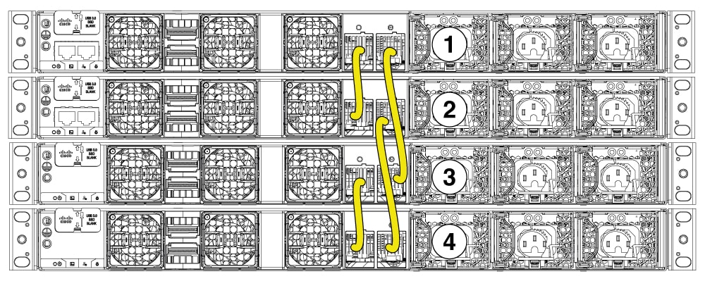
Up to four switches can be configured in a StackPower stack using the StackPower connector at the rear of the switch.
A switch power stack can include a maximum of four switches in a ring topology.
If a switch stack has more than four switches, we will have more than one StackPower groups.
Size of the switch and any optional power supply module: Stacking switches with the same power supply modules together makes it easier to cable the switches. The 1600W power supply module is 3.14 inches (8 cm) longer than the other modules.
Length of cable: Depending on the configurations that you have, you might need different sized cables. If you do not specify the length of the StackPower cable, the 0.35 meter cable is supplied. If you need the 1 meter cable, you can order it from your Cisco supplier. The Data stack cable configurations section provides examples of the recommended configurations.
This section describes the recommended cabling configurations for a StackPower stack.
The two types of StackPower cables are
| Part Number | Cable Type | Length |
|---|---|---|
| CAB-SPWR-35CM= |
StackPower Cable | 0.35 meter |
| CAB-SPWR-100CM= |
StackPower Cable | 1 meter |
The examples in this section displays StackPower stacks of switches with failover conditions.
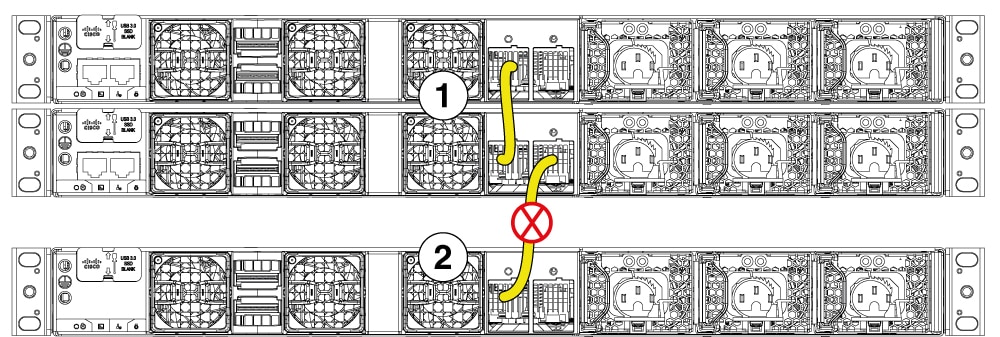
In this illustration, the StackPower cable 2 is faulty. This is considered a broken ring and is a fault condition. Power is still shared across the stack, but this condition will place a limitation on power budgeting and the number of high priority ports it can protect in the case of further failures, such as, failure of power supply, AC mains, StackPower port, and so on. StackPower is not intended for secondary failures and hence restoration of the failed component or power should be done immediately.
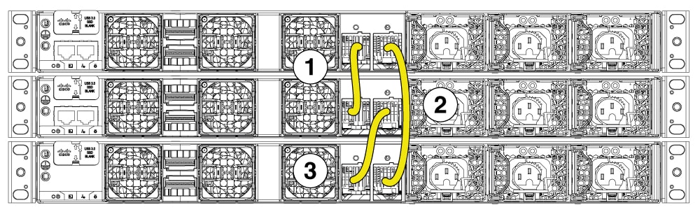
In this illustration, StackPower port B on the center switch has failed and the stack partitions into two stacks. The top two switches share power, and the bottom switch is now a separate stack. After the initial failure of cable 2, any further failure of a port is considered a double fault, which StackPower cannot handle. A double fault could result in unintended high priority ports being shut. If you are unable to physically restore a bad cable, adjust the port priorities and restore any offline supplies, as available.