Cisco C9350 Series Smart Switches Hardware Installation Guide

PDF

Install and remove network modules

Want to summarize with AI?

Log in

Overview

Describes how to install and remove a network module on Cisco 9350 series switches.

This section provides the following information.

  • Safety warnings

  • Network module port configurations

  • Installing a network module

  • Removing a network module

  • Finding the network module serial number


Safety warnings

This section includes the installation cautions and warnings. Translations of the safety warnings are available in the Regulatory Compliance and Safety Information for Cisco C9350 Series Smart Switches.

Caution

Proper ESD protection is required whenever you handle equipment. Installation and maintenance personnel should be properly grounded by grounding straps to eliminate the risk of ESD damage to the equipment. Equipment is subject to ESD damage whenever you remove it.


Network module port configurations

This Cisco C9350 series smart switches support these optional network modules for uplink ports. The port configurations supported for each network module are listed here.

C9350-NM-2C Module

Interface Action

HundredGigE1/1/1

Configurable interface

HundredGigE1/1/2

Configurable interface

C9350-NM-4C Module

Interface Action

HundredGigE1/1/1

Configurable interface

HundredGigE1/1/2

Configurable interface

HundredGigE1/1/3

Configurable interface

HundredGigE1/1/4

Configurable interface

C9350-NM-8Y

You can convert the four top-row ports on C9350-NM-8Y from 25 G to 50 G mode using the hw-module switch command. When the top-row ports are moved to 50 G mode, the bottom-row ports are automatically set to inactive, offering enhanced bandwidth for applications.

The example shows how to convert the ports from 25 G to 50 G:


Device(config)# hw-module switch 1 network-module 
c9350-NM-8Y mode 50G
                    
Interface Action

FiftyGigE1/1/1

Configurable interface

FiftyGigE1/1/2

Configurable interface

FiftyGigE1/1/3

Configurable interface

FiftyGigE1/1/4

Configurable interface

TwentyFiveGigE1/1/5

Configurable interface

TwentyFiveGigE1/1/6

Configurable interface

TwentyFiveGigE1/1/7

Configurable interface

TwentyFiveGigE1/1/8

Configurable interface


Install a network module

Caution
The switch can operate without a network module, but a blank module (with no ports or SFP slots) is available and must always be installed when uplink ports are not required.

Use only supported network modules and Cisco pluggable transceivers. Each module has an internal serial EEPROM that is encoded with security information. The network module is hot-swappable. If you remove a module, replace it with another network module or a blank module.

The switch generates log messages when you insert or remove a network module with SFP/SFP+ slots.

The switch complies with EMC, safety, and thermal specifications when a network module is present.
Before you begin

When installing network modules, observe these precautions.

  • Do not remove the blank module from the slot unless you are installing a network module. A module must be in the uplink slot at all times.

  • Do not remove the dust plugs from the pluggable transceivers or the rubber caps from the fiber-optic cable until you connect the cable. The plugs and caps protect the module ports and cables from contamination and ambient light.

  • Removing and installing a network module can shorten its useful life. Do not remove and insert a network module more often than is necessary.

  • To prevent ESD damage, follow your normal board and component handling procedures when connecting cables to the switch and other devices.

Procedure

1.

Attach an ESD-preventive wrist strap to your wrist and to an earth ground surface.

2.

Remove the module from the protective packaging.

3.

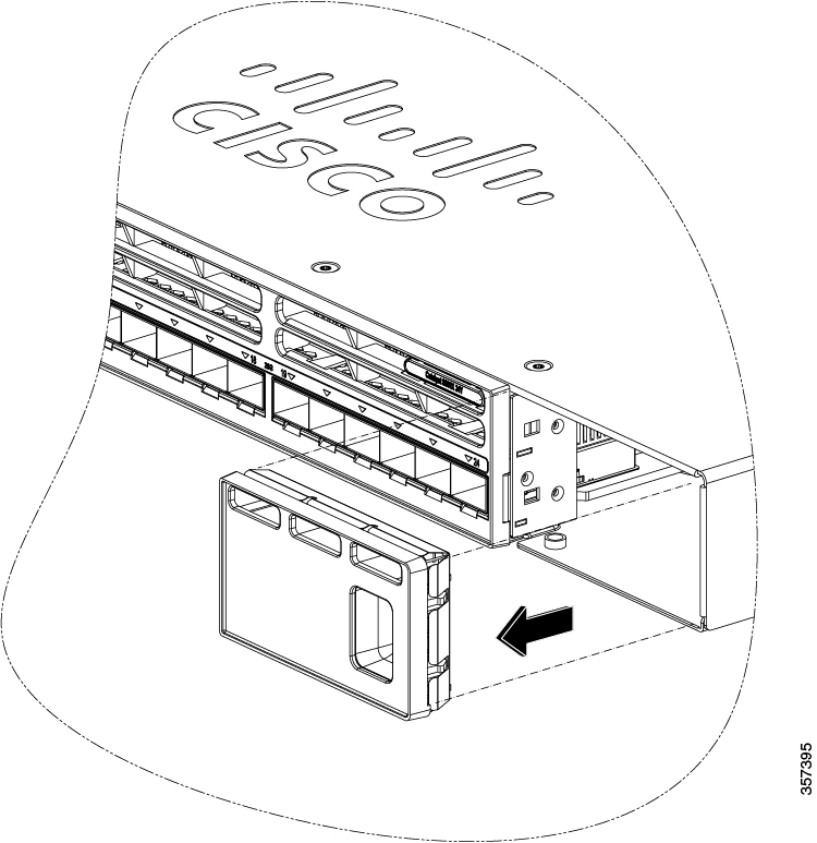
Remove the blank module from the switch and save it.

Figure 1. Remove the blank module

Remove the blank module

Caution

Verify the correct orientation of your module before installing it. Incorrect installation can damage the module.

Caution

Do not install the network module with connected cables or installed pluggable transceivers. Always remove any cables and transceiver modules before you install the network module.

A module interface might become error-disabled when a network module with connected fiber-optic cables is installed or removed. If an interface is error-disabled, you can re-enable the interface by using the shutdown and no shutdown interface configuration commands.

4.

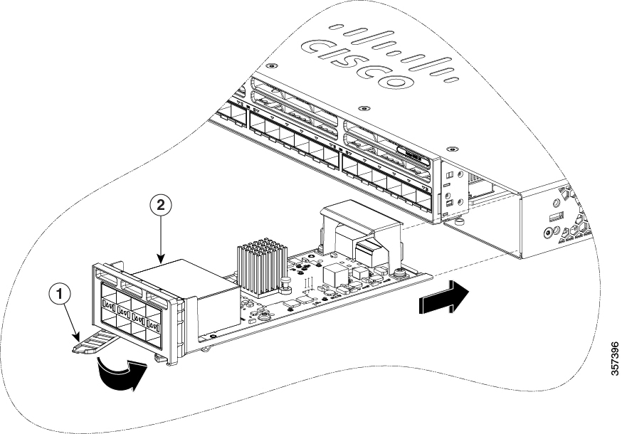
While installing Cisco C9350 network modules, position the module face up to install it in the module slot. Slide the module into the slot until the back of the module faceplate is flush with the switch faceplate. Secure the network module in place by the ejector and the latch.

Figure 2. Install the Cisco C9350 network module
Install the Cisco C9350 network module

Remove a network module

Note

The switch complies with Electromagnetic Compatibility (EMC), safety, and thermal specifications when a network module is present. If no uplink ports are required, install a blank network module in the slot.

Note

To avoid authentication failure and non-detection of modules, wait for a minimum of 6-8 seconds between the online insertion and removal (OIR) of network modules.

Procedure

1.

Attach an ESD-preventive wrist strap to your wrist and to an earth ground surface.

Caution

Do not remove the network module with connected cables or installed pluggable transceiver modules. Always remove any cables and modules before you remove the network module.

Caution

A module interface might become error-disabled when a network module with connected fiber-optic cables is installed or removed. If an interface is error-disabled, you can re-enable the interface by using the shutdown and no shutdown interface configuration commands.

2.

Disconnect the cables from the pluggable transceiver module.

3.

Remove the pluggable transceiver module from the network module.

4.

Press the ejector and latch on the network module until it completely disengages from the chassis.

5.

Carefully slide the network module out of the slot.

6.

Install a replacement network module or a blank module in the slot.

7.

Place the module that you removed in an antistatic bag or other protective environment.